Table of Contents
Advertisement
Quick Links
Thank you for purchasing this product.
Be sure to read this manual before use.
This manual includes important safety precautions and instructions on
how to operate the unit. Be sure to read this manual to ensure proper
operation.
© 2016 JAI
User Manual
SP-12000M-CXP4
SP-12000C-CXP4
12M Digital Progressive Scan
Monochrome and Color Camera
Document Version: 1.0
SP-12000-CXP4_Ver.1.1_Sep.2016
Advertisement
Table of Contents

Related Manuals for JAI SP-12000M-CXP4-XT


Summary of Contents for JAI SP-12000M-CXP4-XT
- Page 1 Thank you for purchasing this product. Be sure to read this manual before use. This manual includes important safety precautions and instructions on how to operate the unit. Be sure to read this manual to ensure proper operation. © 2016 JAI...
-
Page 2: Table Of Contents
SP-12000M-CXP4 / SP-12000C-CXP4 Contents Notice ................3 Video Send Mode ............40 Warranty ...............3 Video Send Mode ...........40 To switch the video send mode ......40 Certifications ..............3 Warning ................3 Multi ROI function ..........40 Sequence Trigger function .........41 Usage Precautions ............6 Features ................7 ALC (Automatic Level Control) Function .....44 To use the ALC function ........44 Parts Identification ............8... -
Page 3: Notice
The material contained in this manual consists of information that is proprietary to JAI Ltd., Japan and may only be used by the purchasers of the product. JAI Ltd., Japan makes no warranty for the use of its product and assumes no responsibility for any errors which may appear or for damages resulting from the use of the information contained herein. - Page 4 SP-12000M-CXP4 / SP-12000C-CXP4 Supplement The following statement is related to the regulation on “ Measures for the Administration of the control of Pollution by Electronic Information Products “ , known as “ China RoHS “. The table shows contained Hazardous Substances in this camera. mark shows that the environment-friendly use period of contained Hazardous Substances is 15 years.
- Page 5 SP-12000M-CXP4 / SP-12000C-CXP4 Supplement The following statement is related to the regulation on “ Measures for the Administration of the control of Pollution by Electronic Information Products “ , known as “ China RoHS “. The table shows contained Hazardous Substances in this camera. mark shows that the environment-friendly use period of contained Hazardous Substances is 15 years.
-
Page 6: Usage Precautions
SP-12000M-CXP4 / SP-12000C-CXP4 Usage Precautions Notes on cable configurations The presence of lighting equipment and television receivers nearby may result in video and audio noise. In such cases, change the cable configurations or placement. Notes on attaching the lens Avoiding dust particles When attaching the lens to the camera, stray dust and other particles may adhere to the sensor surface and rear surface of the lens. -
Page 7: Features
SP-12000M-CXP4 / SP-12000C-CXP4 Features The SP-12000M-CXP4/SP-12000C-CXP4 is an industrial progressive scan camera equipped with an APS-C format global shutter CMOS image sensor with 12.58 effective megapixels (4096 × 3072). The unit is equipped with a CoaXPress Ver. 1.0 interface. ™ The SP-12000M-CXP4 produces monochrome output while the SP-12000C-CXP4 produces Bayer output. Coaxial cable interface supporting CoaXPress Ver. -
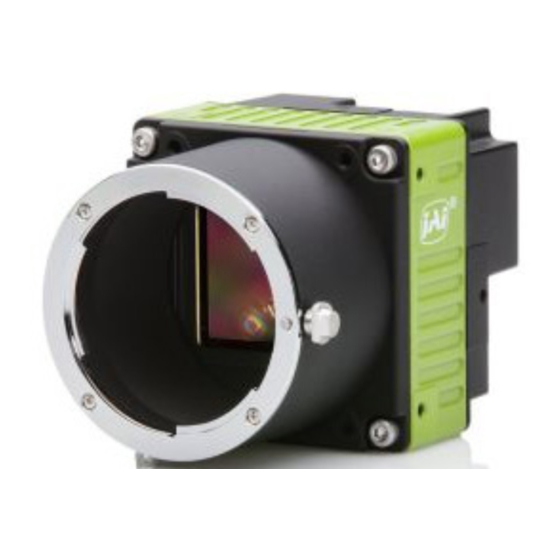
Page 8: Parts Identification
SP-12000M-CXP4 / SP-12000C-CXP4 Parts Identification SP-12000-CXP4 ③ ④ ⑦ ⑤ ① ⑥ ⑧ SP-12000-CXP4-XT (option) ② ③ ④ ⑦ ⑤ ① ⑥ ⑧ — 8 —... - Page 9 SP-12000M-CXP4 / SP-12000C-CXP4 1 Lens mount (F-mount) Mount an F-mount lens, microscope adapter, etc. here. 2 Ventilation holes (SP-12000-CXP4-XT (option) only) 3 CXP (CoaXPress) connectors 1 to 4 (DIN) Connect the coaxial cables for digital video output here. (Equivalent to Amphenol Connex ACX1785-ND.
- Page 10 SP-12000M-CXP4 / SP-12000C-CXP4 5 DC IN / TRIG connector (12-pin round) Connect the cable for a power supply (optional) or for DC IN / trigger IN here. Camera side: Equivalent to Hirose Electronic HR-10A-10R-12PB(72) Cable side: Equivalent to Hirose Electronic HR10A-10P-12S(73) Pin No.
- Page 11 SP-12000M-CXP4 / SP-12000C-CXP4 Recommended internal circuits for Opto OUT User side Camera side TLP109 (TPR,E) Opto OUT+ 180BS TC7WG14FK User power +5V to +24V 220BS 100KBS Opto OUT- 2SC6033 220BS Characteristics of the recommended circuits for Opto OUT OUTPUT LINE RESPONSE TIME Camera Output Signal...
- Page 12 SP-12000M-CXP4 / SP-12000C-CXP4 7 AUX connector (10-pin) Camera side: Equivalent to Hirose Electronic 3260-10S3(55) Cable side: Equivalent to Hirose Electronic 350-10P-C(50) Pin No. Attribute Name Note TTL OUT2 Line 8 TTL OUT3 Line 9 TTL_IN2 Line 10 LVDS_IN1+ Line 11 LVDS_IN1- 8 Camera locking screw holes (M3, 5 mm depth) Use these holes when attaching an MP-42 tripod adapter plate (optional) or mounting the camera...
-
Page 13: Preparation
Note When the JAI SDK is installed, a camera driver for the GigE interface is also part of the default installation. This GigE Vision Filter Driver is added to every NIC/port on the host computer. As the driver is also added to the NIC/ port for Internet connection, it may, on some systems, affect Internet access speed. -
Page 14: Enabling The Cxp Frame Grabber Board
SP-12000M-CXP4 / SP-12000C-CXP4 v Clear the [JAI GigE Vision Filter Driver] checkbox, and save. ■ Enabling the CXP frame grabber board Start JAI Control Tool. Click the settings icon at the top right of the window. The [Settings] window appears. - Page 15 SP-12000M-CXP4 / SP-12000C-CXP4 1 Lens F-mount lenses can be used. Caution The maximum performance of the camera may not be realized depending on the lens. Note The following formula can be used to estimate the focal length. focal length = WD / (1 + W/w) WD: Working distance (distance between lens and object) W: Width of object w: Width of sensor (18.16 mm on this camera)
-
Page 16: Step 3: Verifying The Camera's Connection Status
Connecting to the Camera to Control Tool Start JAI Control Tool. Cameras connected to the CXP frame grabber board are detected and displayed in a window. If they do not appear, right-click inside the window and select [Search for Cameras]. -
Page 17: Configuring The Output Format
SP-12000M-CXP4 / SP-12000C-CXP4 Configuring the Output Format Configure the size, position, and pixel format of the images to be acquired. The factory default settings are as follows. Change the settings as necessary. Factory default values Item Default value Image Format Control Width 4096 (pixels) Height... -
Page 18: Configuring Exposure And External Trigger Settings
SP-12000M-CXP4 / SP-12000C-CXP4 Example: When changing [Pixel Format] Note Direct entry of numerical and text values is possible for some setting items. Configuring Exposure and External Trigger Settings Configure settings related to exposure control methods and trigger control. The factory default settings are as follows. Change settings as necessary, according to the intended purpose or application. -
Page 19: Control Via External Triggers
SP-12000M-CXP4 / SP-12000C-CXP4 Control via External Triggers When Controlling the Exposure Time Using Specified Exposure Times Configure the settings as follows. Item Setting value / selectable range Trigger Selector (trigger operation) Frame Start Trigger Mode Trigger Source (trigger signal source) Trigger Activation (trigger polarity) Rising Edge (rising edge of input signal), Falling Edge (falling edge of input signal) -
Page 20: Control Without External Triggers
SP-12000M-CXP4 / SP-12000C-CXP4 Set [Exposure Mode] to [Trigger Width] . When you select [Trigger Width], [Trigger Mode] will automatically be set to [On]. Set [Trigger Selector] to [Frame Start]. ([Frame Start] is the default setting.) If necessary, change the [Trigger Source] and [Trigger Activation] settings. Other controls In addition to exposure time, the following can also be controlled by external triggers. -
Page 21: When Not Controlling The Exposure Time
SP-12000M-CXP4 / SP-12000C-CXP4 When not Controlling the Exposure Time Configure the settings as follows. Item Setting value / selectable range Exposure Mode Step 5: Adjusting the Image Quality Adjust the image quality using the gain and white balance (SP-12000C-CXP4 only) functions. To adjust the image quality The display level must be changed from [Beginner] to [Guru]. -
Page 22: Adjusting The White Balance (Sp-12000C-Cxp4 Only)
SP-12000M-CXP4 / SP-12000C-CXP4 Adjusting the White Balance (SP-12000C-CXP4 only) Adjust the white balance using R and B gain. The white balance can also be adjusted automatically. ■ Manual white balance adjustment Expand [Analog Control], and set [Balance White Auto] to [Off]. ([Off] is the default setting.) Select the gain to configure in [Gain Selector], and set the gain value in [Gain]. -
Page 23: Step 7: Saving The Settings
SP-12000M-CXP4 / SP-12000C-CXP4 Step 7: Saving the Settings Setting values configured in Control Tool are maintained in the camera’s temporary memory until the camera is turned off. By saving current setting values to user memory, you can load and recall them whenever necessary. -
Page 24: To Load User Settings
SP-12000M-CXP4 / SP-12000C-CXP4 Select [User Set Save], and click [Execute ‘User Set Save’ Command]. The current setting values are saved as user settings. ■ To load user settings Stop image acquisition. User settings can only be loaded when image capture on the camera is stopped. Select the settings to load (User Set1 to User Set3) in [User Set Selector]. -
Page 25: Main Functions
SP-12000M-CXP4 / SP-12000C-CXP4 Main Functions GPIO (Digital Input/Output Settings) The camera is equipped with GPIO (general-purpose input/output) functions for generating and using combinations of triggers and other necessary signals within the camera and of signals output from the camera to the system such as those used for lighting equipment control. Valid Input/Output Combinations The following signals can be used as sources for each output destination (Trigger Selector, Line Selector, Pulse Generator Selector). -
Page 26: Acquisition Control (Image Acquisition Controls)
SP-12000M-CXP4 / SP-12000C-CXP4 Acquisition Control (Image Acquisition Controls) Perform operations and configure settings related to image acquisition in [Acquisition Control]. The following acquisition modes are available on the camera. Acquisition Mode Description Single Frame Acquire a single frame when the [Acquisition Start] command is executed. Multi Frame Acquire the number of frames specified in [Acquisition Frame Count] when the [Acquisition Start] command is executed. -
Page 27: Exposure Mode
SP-12000M-CXP4 / SP-12000C-CXP4 A = MAX (ROUNDUP ((2 × CXP_clocks) × (1 / CXP_clock_Hz) × (Sensor_Clock / Sensor_Reso) - 1), ParameterX) Line_Time = (A + 1) × (1 / Sensor_Clock) × Sensor_Reso FOT = Line_Time × (ParameterY + 2) Readout_Time = Line_Time × Sensor_Height / 2 Camera_FR = 1 / (FOT + Readout_Time) B = ((2 ×... -
Page 28: Trigger Control
SP-12000M-CXP4 / SP-12000C-CXP4 Trigger Option Description When an edge signal is input at the frame start trigger, a single exposure operation is performed. Operate using functions commonly referred to as PIV. When an edge signal is input at the frame start trigger, the exposure operation is performed continuously in the Shutter Off state according to the exposure time configured with [Exposure Time]. - Page 29 SP-12000M-CXP4 / SP-12000C-CXP4 Trigger CMOS exposure Exposure active Exposure duration FVAL 10 μs (minimum) 2.4 μ to 2.4 μ + 1L 14L to 15L Trigger overlap: Off Next trigger input Next trigger start prohibited period Trigger allowed period Sensor Exposure Valid data Period (= Height x Line Period) FVAL...
- Page 30 SP-12000M-CXP4 / SP-12000C-CXP4 Example: When the max. frame rate is used 6G-4 2.4 to 5.8 53.2 -4.2 6G-4 2.4 to 7.5 47.3 -1.9 6G-2 2.4 to 6.9 100.8 -0.8 6G-2 2.4 to 7.5 80.8 6G-1 2.4 to 5.9 195.6 6G-1 2.4 to 19.5 156.5 3G-4...
- Page 31 SP-12000M-CXP4 / SP-12000C-CXP4 Scanning range Shortest period trigger Full 5.275 ms ROI 2/3 3.351 ms ROI 1/2 2.534 ms ROI 1/4 1.296 ms ROI 1/8 0.885 ms * SP-12000M-CXP4 only Trigger CMOS exposure Exposure active Exposure duration FVAL 10 μs (8-bit), 15 μs (10-bit) 4.0 μ...
- Page 32 SP-12000M-CXP4 / SP-12000C-CXP4 Example: When the max. frame rate is used 6G-4 2.40 2.4 to 6 53.2 -4.2 6G-4 2.40 2.4 to 7.4 47.3 -5.4 6G-2 2.40 2.4 to 8.8 100.8 -0.8 6G-2 2.40 2.4 to 11.1 80.7 -4.9 6G-1 2.40 2.4 to 8.8 195.6...
- Page 33 SP-12000M-CXP4 / SP-12000C-CXP4 3. PIV-Trigger Mode Example: When [Frame Start Trigger] is [On] and [Exposure Mode] is [Timed] Selector Value Trigger Option Trigger Source Line4-TTL in 1 Opt In Filter Selector Overlap Pixel Format 8-bit Exposure Time 15 μs Scanning range Shortest period trigger Full 10.555 ms...
- Page 34 SP-12000M-CXP4 / SP-12000C-CXP4 6G-4 (14 + Height / 2) × H* 14H* (8 bit) 15H* (8 bit) 11.0 14H* –3.0 (8 bit) 9H* (10 bit) 10H* (10 bit) 9H* –3.0 (10 bit) 6G-4 6G-2 6G-2 6G-1 6G-1 3G-4 3G-4 3G-2 3G-2 3G-1 3G-1...
- Page 35 SP-12000M-CXP4 / SP-12000C-CXP4 Timing chart (Trigger Off, Exposure Mode Off) Continuous, Shutter Off FVAL Valid data Period (= Height x Line Period) Sensor Exposure ActualExposureTime (= Frame Period – B) Frame Period (= 1/ Acquisition Frame rate) Timing chart (Trigger Off, Exposure Mode Timed) Continuous, Shutter Mode FVAL Valid data Period...
-
Page 36: Gain Control
SP-12000M-CXP4 / SP-12000C-CXP4 Formulas for each Link Config Period from FVAL end Period of exposure Link Config Dig Bit Sensor Dig Bit Frame Rate [Hz] to exposure end [A] stop [B] 6G-4 (14 + Height / 2) × H 0 to 1H 16H to 17H (8-bit) 11H to 12H (10-bit) 6G-4... -
Page 37: Lut (Lookup Table)
(indexes). ■ To use the LUT function Configure the settings as follows. Item Setting value / selectable range Description JAI LUT Mode Use LUT. LUT Selector* R, G, B Select the LUT channel to control. LUT Index SP-12000M-CXP4: 0 to 255 Select the LUT index to configure. -
Page 38: Gamma Function
Gamma 0.45, 0.5, 0.55, 0.6, 0.65, 0.75, Select the gamma correction value. 0.8, 0.9, 1.0 (9 steps) JAI LUT Mode Gamma Use gamma. Note You can use the LUT function to configure a curve with more detailed points. For details, see “LUT (Lookup Table)”... -
Page 39: Roi (Regional Scanning Function)
SP-12000M-CXP4 / SP-12000C-CXP4 ROI (Regional Scanning Function) The ROI (region of interest) function allows you to output images by specifying the areas to scan. ROI Settings Specify the area to scan by specifying width, height, and horizontal/vertical offset values under [Image Format Control]. -
Page 40: Video Send Mode
SP-12000M-CXP4 / SP-12000C-CXP4 Video Send Mode Switch the video send mode to configure and operate Multi ROI, Sequence Trigger, and other JAI Custom Control functions. Video Send Mode ■ To switch the video send mode Select the video send mode in [Video Send Mode Selector]. -
Page 41: Sequence Trigger Function
SP-12000M-CXP4 / SP-12000C-CXP4 ■ Sequence Trigger function The Sequence Trigger function lets you define up to 128 preset combinations of exposure time, gain, ROI, and other settings which can be stepped through each time a trigger is received. This is particularly useful for quickly capturing multiple exposures of objects under inspection to adjust for areas or components with significantly different levels of reflectance. - Page 42 SP-12000M-CXP4 / SP-12000C-CXP4 Index structure for Trigger Sequence Index Selector Exposure Black Next Frame Binning1 Gain1 Index1 ROI1 Level1 Enable1 Count1 Index1 (M/Red/Blue) (H/V) (MUX) Exposure Black Frame Next Gain2 Binning2 Index2 ROI2 Level2 Enable2 Count2 Index2 (M/Red/Blue) (H/V) Current Index Exposure Black...
- Page 43 SP-12000M-CXP4 / SP-12000C-CXP4 Command Sequence Example User-defined Indexes (up to 128) Index1 Index2 Index3 Exposure Exposure Exposure Gain Gain Gain Binning Binning Binning Set to Set to Set to Set to Set to Set to Index1 Index1 Index3 Index1 Index2 Index2 Command Sequence...
-
Page 44: Alc (Automatic Level Control) Function
Set [Gain Auto] or [Exposure Auto] or both to [Continuous] mode. Configure the minimum value, maximum value, etc. for AGC and ASC under [JAI Custom Control]. The target video levels for AGC and ASC are configured in [ALC Reference]. For example, when [ALC Reference] is set to 100%, video levels will be maintained at 100% for AGC and ASC. -
Page 45: Piv Function
SP-12000M-CXP4 / SP-12000C-CXP4 Auto gain metering areas (16 areas) High High High High Mid-left Mid-right Right Left Mid-High Mid-High Mid-High Mid-High Left Mid-left Mid-right Right Mid-Low Mid-Low Mid-Low Mid-Low Mid-left Mid-right Right Left Mid-left Mid-right Right Left PIV Function The PIV function allows you to perform exposure and scanning twice in succession in response to a single trigger. -
Page 46: Hdr (High Dynamic Range) Mode (Sp-12000M-Cxp4 Only)
SP-12000M-CXP4 / SP-12000C-CXP4 HDR (High Dynamic Range) Mode (SP-12000M-CXP4 only) HDR (high dynamic range) mode is a function that uses the exposure time configured with [Exposure Time] as a base, and allows you to determine input level positions for knee points. You can change the number of knee points from 1 to 2. - Page 47 SP-12000M-CXP4 / SP-12000C-CXP4 Item Setting value / selectable range Description Knee Slope 3 2 to 16 Use this to determine the position of knee point 2 (step=1) based on the [Exposure Time] value. The knee slope 3 value is a value by which the [Exposure Time] will be divided.
-
Page 48: Video Process Bypass Mode
SP-12000M-CXP4 / SP-12000C-CXP4 Video Process Bypass Mode The Video Process Bypass mode is a function that bypasses internal image processing on the camera. On the SP-12000, DSNU correction and shading, gain, blemish, and black level adjustment are normally performed on the sensor output signal. However, when the Video Process Bypass mode is used, images can be imported to the system without image processing* being performed internally on the camera. -
Page 49: Settings List
Displays the XML URL string starting address. IidcPointer — Displays the IIDC register area starting address. As this is not supported, 0 is displayed. DeviceVendorName — JAI Ltd, Japan Displays the manufacturer name. DeviceModelName — SP-12000M-CXP4 or Displays the model name. SP-12000C-CXP4 DeviceManufactureInfo —... - Page 50 SP-12000M-CXP4 / SP-12000C-CXP4 Item Setting range Default value Description DeviceTemperature — — Displays the internal temperature (°C) of the camera. DeviceReset — — Reset the device. Configure image format settings. b) Image Format Control SensorWidth — 4096 Displays the maximum image width. SensorHeight —...
- Page 51 Off, Once, Continuous Enable/disable gain auto control. BalanceWhiteAuto Off, On Enable/disable auto white balance. LutMode Off, Gamma, LUT Select the JAI LUT mode. Gamma 1.0 to 0.45 0.45 Set the gamma value. e) Digital IO Control Configure settings for digital input/output.
- Page 52 — Load user settings. UserSetSave — — Save the current setting values as user settings. Configure JAI ALC settings. These i) JAICustomControl settings are also used for AGC (auto gain control). TriggerOption Off,PIV When [ExposureMode] is set to [Timed], select from normal trigger operation or PIV operation.
- Page 53 SP-12000M-CXP4 / SP-12000C-CXP4 Item Setting range Default value Description AWBAreaEnableAll 0 to 1 Enable/disable the all measurement area. BlemishReductionEnable True, False True Set whether to enable white blemish correction. BlemishReductionCalibration — — Set whether to enable white blemish correction. BlemishDetectThreshold 0 to 100 Set the white blemish detection threshold.
-
Page 54: Settings
Counter0 to 3 Status — Counter Active Displays the counter status. Settings ™ For details on the setting items, refer to the JAI Control Tool User’s Guide Item Setting range Default value 32-bit Factory Transport Layers Available 32-bit Transport Layers —... - Page 55 Prompt user for AVI Encoder True, False True CXP Transport Layer Sync Remote And Local Devices True, False True File Save File Format Tiff, Jpeg, Bmp, Jai, RAW Tiff Encoder parameter — Look-and-feel Visibility Level Beginner, Expert, Guru Beginner HEX display...
-
Page 56: Miscellaneous
SP-12000M-CXP4 / SP-12000C-CXP4 Miscellaneous Troubleshooting Check the following before requesting help. If the problem persists, contact your local JAI distributor. ■ Power supply and connections Problem Cause and solution The POWER / TRIG LED remains lit amber and Camera initialization may not be complete due to lack of a does not turn green, even after power is CXP connection. -
Page 57: Specifications
SP-12000M-CXP4 / SP-12000C-CXP4 Specifications Item SP-12000M-CXP4 SP-12000C-CXP4 Scanning system Progressive scan, 1 tap Synchronization Internal Interface CoaXPress Ver. 1.0 Image sensor APS-C monochrome CMOS APS-C Bayer color CMOS Aspect ratio Image size (effective image) 22.5 (H) × 16.9 (V), 28.16 mm diagonal Pixel size 5.5 (H) ×... - Page 58 SP-12000M-CXP4 / SP-12000C-CXP4 Item SP-12000M-CXP4 SP-12000C-CXP4 Gain adjustment Manual adjustment range 0 dB to +24 dB 0 dB to +24 dB 1 step = x0.01 (0.005 dB to 1 step = x0.01 (0.005 dB to 0.08 dB) 0.08 dB) (varies by setting value) (varies by setting value) Auto gain Off, Continuous...
-
Page 59: Frame Rate Reference
SP-12000M-CXP4 / SP-12000C-CXP4 Frame Rate Reference (Theoretical value: decimal values are dropped) Sensor scanning Pixel size Pixel count Resolution ROI/Binning Image size Frame rate resolution (μm) 12 MP 4096 × 3072 4096×3072 Full pixel 5.5 × 5.5 APS size (2") 189 fps (@8-bit) (28.16 mm diagonal) 132 fps (@10-bit) -
Page 60: Dimensions
SP-12000M-CXP4 / SP-12000C-CXP4 SP-12000C-CXP4 SP-12000C Spectral Sensitivity 1000 1100 wave length (nm) Dimensions — 60 —... -
Page 61: User's Record
Revision: …………….. Serial No. …………….. Firmware version. …………….. For camera revision history, please contact your local JAI distributor. Trademarks • Microsoft and Windows are trademarks or registered trademarks of Microsoft Corporation in the United States and other countries. • Intel and Intel Core are trademarks of Intel Corporation in the United States and other countries. -
Page 62: Index
SP-12000M-CXP4 / SP-12000C-CXP4 Index 6-pin round 10 JAI Camera Control Tool 13 white balance 22 JAI SDK 13 AC adapter 15 Acquisition Control 26 acquisition modes 26 LED 9 Adjusting the Black Level 22 Lens 15 Adjusting the Gain 21... - Page 63 Revision History Revision Date Changes May 2016 First edition Sept. 2016 Revised frame rate frequency calculation formulas and frame rate values (p. 28, 32 to 34, 38, 66)
Need help?
Do you have a question about the SP-12000M-CXP4-XT and is the answer not in the manual?
Questions and answers