Table of Contents
Advertisement
Quick Links
User Manual
SP-25000M-CXP4A
SP-25000C-CXP4A
25M CMOS Digital Progressive Scan
Monochrome and color Camera
Document Version: 1.1
SP-25000MC-CXP4A_Ver.1.1_Apr.2021
Thank you for purchasing this product.
Be sure to read this manual before use.
This manual includes important safety precautions and instructions on how to operate the unit. Be sure
to read this manual to ensure proper operation.
The contents of this manual are subject to change without notice for the purpose of improvement.
© 2021 JAI
Advertisement
Table of Contents

Related Manuals for JAI SP-25000M-CXP4A


Summary of Contents for JAI SP-25000M-CXP4A
- Page 1 This manual includes important safety precautions and instructions on how to operate the unit. Be sure to read this manual to ensure proper operation. The contents of this manual are subject to change without notice for the purpose of improvement. © 2021 JAI...
-
Page 2: Notice/Warranty/Certifications
The material contained in this manual consists of information that is proprietary to JAI Ltd., Japan and may only be used by the purchasers of the product. JAI Ltd., Japan makes no warranty for the use of its product and assumes no responsibility for any errors which may appear or for damages resulting from the use of the information contained herein. -
Page 3: Table Of Contents
SP-25000M-CXP4A/SP-25000C-CXP4A Contents Blemish Compensation Notice/Warranty/Certifications Shading Correction Usage Precautions Binning Function Features ROI Function (Single ROI) Parts Identifications ROI Function (Multi ROI) Overlay mode Preparation Image flip function Preparation Process Edge enhancer Step 1:Connecting Devices CXP Link Sharing function Step 2:Verifying Camera Operation... - Page 4 BlemishControl MultiROIControl LensCommunicationControl About Technical Note ■ Some additional technical information is provided on the JAI website as Technical Notes. In this manual, if a technical note is available for a particular topic, the icon is shown. Technical notes Please refer to the following URL for Technical notes.
- Page 5 SP-25000M-CXP4A/SP-25000C-CXP4A Supplement The following statement is related to the regulation on “Measures for the Administration of the control of Pollution by Electronic Information Products“ , known as “China RoHS“. The table shows contained Hazardous Substances in this camera. mark shows that the environment-friendly use period of contained Hazardous Substances is 15 years.
-
Page 6: Usage Precautions
SP-25000M-CXP4A/SP-25000C-CXP4A Usage Precautions Notes on cable configurations The presence of lighting equipment and television receivers nearby may result in video noise. In such cases, change the cable configurations or placement. Notes on temperature conditions The guaranteed operating temperature and humidity of this camera are -5℃ to +45℃, 20% to 80% (non-condensing). -
Page 7: Features
SP-25000M-CXP4A/SP-25000C-CXP4A Features SP-25000M-CXP4A/SP-25000C-CXP4A are new members of JAI’s Spark Series, which provides an attractive combination of high resolution, high speed, and high image quality for machine vision applications. SP-25000M-CXP4A produces monochrome output and SP-25000C-CXP4A produces Bayer output. Both are industrial progressive scan cameras using a CMOS image sensor with a global shutter and an optical format of 1.1-inch (diagonal 18.1mm). -
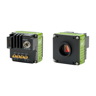
Page 8: Parts Identifications
SP-25000M-CXP4A/SP-25000C-CXP4A Parts Identification ② ⑥ ⑤ ③ ① ⑧ ④ ⑦ ① Lens mount(C-mount) Mount a C-mount lens, microscope adapter, etc. here. ❖ Before mounting a lens, be sure to refer to “Step 2:Connecting Devices” and confirm the precautions for attaching a lens and the supported lens types. - Page 9 SP-25000M-CXP4A/SP-25000C-CXP4A ③ CXP (CoaXPress) connector 1~4 Coaxial cable for digital video output Connect. (The camera connector (Amphenol RF 034-1028-12G equivalent) is used.) The CxpLink Configuration supported by this camera are as follows. CXP12_X4*, CXP12_X3*, CXP12_X2*, CXP12_X1* CXP6_X4, CXP6_X3, CXP6_X2, CXP6_X1 Caution ・*The CxpLink Configuration (CXP12_X4, CXP12_X3, CXP12_X2, CXP12_X1) can only...
- Page 10 SP-25000M-CXP4A/SP-25000C-CXP4A ⑤ DC IN/TRIG connector(12-pin round) Connect the cable for a power supply (optional) or for DC IN / trigger IN here. Compatible connectors Camera side : HR10A-10R-12PB(71)(Hirose Electric or equivalent ) Cable side : HR10A-10P-12S (plug) (Hirose Electric or equivalent )...
- Page 11 SP-25000M-CXP4A/SP-25000C-CXP4A Note When supplying power via the DC IN/TRIG connector, please note the maximum current rating for the power and ground pins is 1.6A per pin pair. If you are using a power supply whose voltage would create a current flow above this limit in order to meet the camera’s maximum power consumption (21.2W), then power must be...
- Page 12 SP-25000M-CXP4A/SP-25000C-CXP4A TTL signal specification TTL out signal specification (Typ.) Output voltage: Low 0.0V High 5.0V TTL in signal specification (Typ.) Input voltage: Low 0.0~0.8V High 2.0~5.5V ■ Recommended external input circuit diagram (reference example) (*1) (*2) Opto In 1 : (*1) Pin6 (Opto In 1+)
- Page 13 SP-25000M-CXP4A/SP-25000C-CXP4A ■Characteristics of the recommended circuits for Opto OUT OUTPUT LINE RESPONSE TIME Camera Output Signal Output Line Voltage For the operating conditions of applied voltage (User Power) +12V, load resistance 10kΩ, and cable length 1m, the timing is shown in the table below.
- Page 14 SP-25000M-CXP4A/SP-25000C-CXP4A ⑥ AUX connector(10-pin) Camera side:3260-10S3 (55) (Hirose Electric or equivalent) Cable side :3240-10P-C (50) (Hirose Electric or equivalent) Pin No. Signal Description Input/Output TTL Out 2 Line 8 N.C. TTL In 2 Line 10 N.C. DC Out LENS Power...
-
Page 15: Preparation
SP-25000M-CXP4A/SP-25000C-CXP4A Preparation Preparation Process Connecting Devices Step 1 Connect the lens, CXP frame grabber, AC adapter, computer and other devices. Verifying Camera Operation Step 2 Verify whether the camera is turned on and ready for use. Verifying the Connection between the Camera and PC Step 3 Set settings and display image using suitable tool for CXP frame grabber board. -
Page 16: Step 1:Connecting Devices
SP-25000M-CXP4A/SP-25000C-CXP4A Step 1: Connecting Devices ⑥ AC adapter (not supplied) Camera body ⑤ DC IN/Trigger IN CXP-1 connection cable CXP-2 ③ CoaXPress cable ①Lens CXP-3 ④ CoaXPress frame grabber board CXP-4 CXP-1 ② Direct connection CXP-2 (or MP-42 tripod adapter plate) -
Page 17: Step 2:Verifying Camera Operation
SP-25000M-CXP4A/SP-25000C-CXP4A ④ CXP frame grabber board Refer to the operating instructions of the frame grabber board, and configure settings on the computer as necessary. ⑤ DC IN / trigger IN connection cable ⑥ AC adapter (power supply) Connect the AC adapter and the round connector of the connection cable to the DC IN / TRIG IN connector on the camera. -
Page 18: Step 4:Adjusting The Image Quality
SP-25000M-CXP4A/SP-25000C-CXP4A Step 4: Adjusting the Image Quality Adjusting the Gain To adjust the image quality The Visibility must be changed from [Beginner] to [Guru]. At first, adjust the sensitivity via the analog base gain. Next, set digital gain. For details on gain control, see “Gain Control”... -
Page 19: Step 5:Saving The Settings
SP-25000M-CXP4A/SP-25000C-CXP4A Step 5: Saving the Settings The setting values configured in the tool will be deleted when the camera is turned off. By saving current setting values to user memory, you can load and recall them whenever necessary. You can save up to three sets of user settings in the camera. (User Set1 to 3) Memory(Flash) 一時メモリ... -
Page 20: Main Functions
SP-25000M-CXP4A/SP-25000C-CXP4A Main Functions Acquisition Control This camera has three Acquisition modes (SingleFrame, MultFrame, Continuous). Use [AcquisitionControl] settings to perform operations and settings for image capture. SingleFrame When the [AcquisitionStart] command is executed, one frame of image is captured. Acquisition Acquisition... -
Page 21: Exposure Mode
SP-25000M-CXP4A/SP-25000C-CXP4A Exposure Mode This camera has three Exposure modes (Off, Timed, TriggerWidth). Use [AcquisitionControl] settings to perform operations and settings for exposure. ExposureMode = Off Exposure control is not performed (free-running operation). The exposure time is the longest possible time within the operating conditions such as the frame rate. -
Page 22: Trigger Control
SP-25000M-CXP4A/SP-25000C-CXP4A Trigger Control The camera allows the following controls to be performed via external trigger signals. TriggerSelector Description AcquisitionStart Start image acquisition in response to the external trigger signal input. AcquisitionEnd Stop image acquisition in response to the external trigger signal input. -
Page 23: Pixel Format
SP-25000M-CXP4A/SP-25000C-CXP4A Pixel Format Supported PixelFormat is as follows. SP-25000C-CXP4A : BayerGB8, BayerRG8, BayerBG8, BayerGR8 SP-25000M-CXP4A : Mono8 Note 1. In SP-25000C-CXP4A, the Bayer array is changed by the image flip function. (Please refer to “Image flip function”) ReverseX : 0 (False) ReverseY : 0 (False) -> BayerGB ReverseX : 0 (False) ReverseY : 1 (True) ->... -
Page 24: Gpio (Digital Input/Output Settings)
SP-25000M-CXP4A/SP-25000C-CXP4A GPIO (Digital Input/Output Settings) The unit can input/output the following signals to and from external input/output connectors. Line1 : TTL Out 1 DC IN / TRIG IN connector (12-pin round) External Line2 : Opt Out 1 DC IN / TRIG IN connector (12-pin round) - Page 25 SP-25000M-CXP4A/SP-25000C-CXP4A For digital output, set the output source signal using [LineSource]. Set the source signal in the same way for NAND Logic (Nand0In1, Nand0In2, Nand1In1, NandIn2) and TimestampReset. The table below shows the source signals that can be set. ✓ ✓ ✓ ✓ ✓ ✓ ✓ ✓ ✓ ✓ ✓ ✓ ✓ ✓ ✓ ✓ ✓ ✓ ✓ ✓ ✓ ✓ ✓...
-
Page 26: Videoprocessbypassmode
SP-25000M-CXP4A/SP-25000C-CXP4A VideoProcessBypassMode The video process bypass mode is a function that bypasses internal video processing on the camera. When bypass is enabled, the sensor output and camera output data can be set to the same bit width. ■ Functions available in VideoProcessBypassMode... -
Page 27: Timming Chart
SP-25000M-CXP4A/SP-25000C-CXP4A Timing chart ■ When [ExposureMode] is [Timed] • FrameStartTrigger On A (Frame Period) Next trigger Input enabled Next trigger disabled Trigger Sensor Exposure Exposure Exposure time Active Readout CXP12-4 Period From Trigger start edge to PixelFormat Frame Period [A] (usec) - Page 28 SP-25000M-CXP4A/SP-25000C-CXP4A ■ When [ExposureMode] is [TriggerWidth] • FrameStartTrigger On A (Frame Period) Next trigger Input enabled Next trigger disabled Trigger Sensor Exposure Exposure ExposureTime Active Readout CXP12-4 Period From Trigger start edge to Period From Trigger end to PixelFormat Frame Period [A] (usec)
-
Page 29: Maximum Frame Rate Reference
SP-25000M-CXP4A/SP-25000C-CXP4A Maximum Frame Rate Reference The table below shows the maximum frame rate in normal mode. [Theoretical value] PixelFormat Width Height Maximum frame rate(fps) 5120 5120 CXP12-4 Mono8/Bayer8 5120 3840 5120 2560 PixelFormat Width Height Maximum frame rate(fps) 5120 5120... -
Page 30: Calculate The Maximum Frame Rate (Approximate)
SP-25000M-CXP4A/SP-25000C-CXP4A Calculate the maximum frame rate (approximate) Maximum frame rate This section describes how to calculate the maximum frame rate. ■ LinePeriod[μs] The Value (A) is a fixed value for each LinkConfig(CoaXPress) and PixelFormat. Please refer to the table below. -
Page 31: Gain Control
-7dB -7dB 15dB 15dB x 1.0 -7dB -7dB In SP-25000M-CXP4A, adjust the [DigitalAll] (master gain) setting. Digital All x 16 24dB x 1.0 ■ Automatic Gain Level Control Set [GainAuto] to [Continuous] to control the gain level automatically. When [GainAuto] is set to [Continuous], you can configure the conditions for automatic adjustment in detail. -
Page 32: White Balance
SP-25000M-CXP4A/SP-25000C-CXP4A White Balance To adjust the white balance automatically, set [BalanceWhiteAuto] to Once (automatic adjustment only once) or Continuous (automatic adjustment always). The metering area can be limited for automatic adjustment. To limit the metering area, specify each of the 16 areas with [AWBAreaSelector] and set [AWBAreaEnable] to True or False. -
Page 33: Alc (Automatic Level Control) Function
SP-25000M-CXP4A/SP-25000C-CXP4A ALC (Automatic Level Control) Function The ALC (automatic level control) function combines the automatic gain control (AGC/Auto Gain Control) and automatic exposure control (ASC/Auto Shutter Control) functions, and is capable of handling various changes in brightness.The function operates as follows in response to changes in brightness. -
Page 34: Gamma Function
SP-25000M-CXP4A/SP-25000C-CXP4A Gamma Function The gamma function corrects the output signals from the camera beforehand (reverse correction), taking into consideration the light-emitting properties of the monitor display. As the light-emitting properties of the monitor are not linear, the entire image may be darker or the gradation in the dark areas may be less noticeable when camera outputs are displayed without processing. -
Page 35: Lookup Table (Lut)
SP-25000M-CXP4A/SP-25000C-CXP4A LUT (Lookup Table) The LUT function is used to generate a non-linear mapping between signal values captured on the sensor and those that are output from the camera. You can specify the output curve using 257 setting points (indexes). -
Page 36: Blemishcompensation
SP-25000M-CXP4A/SP-25000C-CXP4A BlemishCompensation Multiple defective pixels that are not adjacent to each other can occur on conventional CMOS sensor cameras. This camera features a function that interpolates defective pixels using the surrounding pixels. Up to 2000 pixels can be corrected. Pixel interpolation can be performed via automatic detection or point-by-point manual settings. -
Page 37: Shading Correction
SP-25000M-CXP4A/SP-25000C-CXP4A Shading Correction The ShadingCorrection function corrects non-uniformity (i.e., shading) in the amount of light generated by the lens and lighting equipment. Using this function allows correction even if top, bottom, left, and right shading is not symmetrical in relation to the center of the screen (H, V). -
Page 38: Binning Function
[ShadingMode]. Binning Function SP-25000M-CXP4A only The binning function allows you to combine the signal values of clusters of adjacent pixels to create improved virtual pixels. Using the function results in images with lower pixel resolution and higher sensitivity. -
Page 39: Roi Function (Single Roi)
SP-25000M-CXP4A/SP-25000C-CXP4A ROI Function (Single ROI) The ROI (region of interest) function allows you to output images by specifying the areas to scan. Specify the area to scan by specifying width, height, and horizontal/vertical offset values under [ImageFormatControl]. For details on how to configure the settings, see “Configuring the Output Format”. -
Page 40: Roi Function (Multi Roi)
SP-25000M-CXP4A/SP-25000C-CXP4A ROI Function (Multi ROI) In the Multi ROI mode, you can specify up to 64 scanning areas for a single-frame image. The areas cannot overlap. The Multi ROI mode can be used only when both the Sequencer mode and the Shading mode are off. -
Page 41: Overlay Mode
SP-25000M-CXP4A/SP-25000C-CXP4A Overlay mode In this mode, you can check the readout area when using the Multi ROI function. The area that is not read out is displayed with the brightness reduced to half. This makes it possible to set and adjust the readout area while checking the target area on the screen. -
Page 42: Image Flip Function
BayerRG8 BayerGR8 Edge enhancer SP-25000M-CXP4A is equipped with an edge enhancer function for enhancing the contrast of lines or edges within images. The edge enhancer function is enabled when EnhancerEnable[Edge] is set to True. Four enhancement levels are available: Low, Middle, High, and Strong. -
Page 43: Cxp Link Sharing Function
SP-25000M-CXP4A/SP-25000C-CXP4A CXP Link Sharing function This function has two operation modes (Sharing mode and Duplicate mode). ■Sharing mode This camera can be connected to multiple PCs and the captured images can be divided and sent to each PC. ① ②... - Page 44 SP-25000M-CXP4A/SP-25000C-CXP4A It is also possible to divide the captured image shown below. ■ Duplicate mode This camera can be connected to multiple PCs and the same captured image can be copied and sent to each PC. [LINK-1] CXP Master connection (LinkSharing Status: Master)
-
Page 45: Sequencer Function
SP-25000M-CXP4A/SP-25000C-CXP4A Sequencer Function The Sequencer function lets you define up to 128 index combinations of exposure time, gain, ROI, and other settings which can be stepped through each time a trigger is received.This is particularly useful for quickly capturing multiple exposures of objects under inspection to adjust for areas or components with significantly different levels of reflectance. - Page 46 SP-25000M-CXP4A/SP-25000C-CXP4A Sample TriggerSequencer mode operation User-defined Indexes (up to 128) Triggers/ Image Frames Specify "1" in [SequencerSetStart], and start TriggerSequencer mode with index 1. Capture a 2-frame image with the first and second triggers. For the next index, configure index 3 specified in [SequencerSetNext], and capture an image with the number of frames (number of triggers) specified in [SequencerFrameNumber].
-
Page 47: Pulse Generator
SP-25000M-CXP4A/SP-25000C-CXP4A Pulse Generator By using this function, any signal can be generated inside the camera. The following is an example of signal generation. Settings PulseGeneratorStartPoint = 2 PulseGeneratorEndPoint = 6 PulseGeneratorLength = 10 PulseGeneratorPulseWidth = 4 PulseGeneratorClearSyncMode = AsyncMode StartPoint... -
Page 48: Counter And Timer Control Function
SP-25000M-CXP4A/SP-25000C-CXP4A Counter And Timer Control Function This camera supports only the counter function. The counter function counts up change points in the camera’s internal signals using the camera’s internal counter, and reads that information from the host side. This function is useful for verifying error conditions via the count value using internal camera operations. - Page 49 SP-25000M-CXP4A/SP-25000C-CXP4A ■ Internal camera blocks Counter0 Counter Event detection FrameStartTrigger At event occurrence or count up Counter1 Counter Event detection ExposureStart At event occurrence or count up Counter2 Counter Event detection SensorReadOut At event occurrence or count up Counter3 Counter...
-
Page 50: Lens Control (Transfer Camera Control Commands)
SP-25000M-CXP4A/SP-25000C-CXP4A Lens control (Transfer camera control commands) By connecting this camera to a Birger Mount Adapter via RS-232C and transferring the lens control command sent via CoaXPress to the camera, the lens can be controlled via this camera. This mode is enabled when [Lens Communication Enable] in [Lens Communication Control] is set to [True]. -
Page 51: Setting List
SP-25000M-CXP4A/SP-25000C-CXP4A Setting List This camera complies with GenICam. Each setting item name conforms to GenICam SFNC (Standard Features Naming Convention). (There are some JAI-specific setting items). Each setting item is an integer type (IInteger), a real type (IFloat), an element... -
Page 52: Feature Properties
SP-25000M-CXP4A/SP-25000C-CXP4A Feature Properties Item Setting range Default value Description DeviceControl Display/configure information related to the device. DeviceScanType ー Areascan Display the scan type. DeviceVendorName ー "JAI Corporation" Display the manufacturer name. DeviceModelName ー SP-25000M-CXP4A, Display the model name. SP-25000C-CXP4A DeviceManufacturerInfo ー... - Page 53 SP-25000M-CXP4A/SP-25000C-CXP4A Item Setting range Default value Description TransportLayerControl Display information on transport layer control. PlayloadSize 32〜268369920 44728320 Display the payload size. DeviceTapGeometry ー Geometry_1X_1Y Set the Tap Geometry. [Setting range] 0:Geometry_1X_1Y, 1:Geometry_2X_1Y, 2:Geometry_3X_1Y 3:Geometry_4X_1Y, 4:Geometry_8X_1Y CoaXPress CxpLinkConfigurationPreferred The Link configuration is returned as the combination of the Connection speed and the number of active Connections using the following format "CXPm_Xn", where m is the Connection speed and n the number of active...
- Page 54 SP-25000C-CXP4A : Set the pixel format. BayerRG8 In SP-25000C-CXP4A, the PixelFormat that can be set differs depending on the ReverseX settings. SP-25000M-CXP4A : [Setting range] Mono8 [SP-25000C-CXP4A] ReverseX : 0 (False) ReverseY : 0 (False) -> 0x0108000A:BayerGB8 ReverseX : 0 (False) ReverseY : 1 (True) -> 0x01080009:BayerRG8 ReverseX : 1 (True) ReverseY : 0 (False) ->...
- Page 55 SP-25000M-CXP4A/SP-25000C-CXP4A Item Setting range Default value Description AcquisitionControl Configure image capture settings. AcquisitionMode 0:SingleFrame, Countinuous Select the image capture mode. 1:MultiFrame, 2:Continuous AcquisitionStart ー ー Start image capture. AcquisitionStop ー ー Stop image capture. AcquisitionFrameCount 1〜65535 In [MultiFrame] mode, set the number of frames to capture.
- Page 56 SP-25000M-CXP4A/SP-25000C-CXP4A Item Setting range Default value Description DigitalIOcontrol Configure settings for digital input/output. LineSelector ー Line1 Select the input/output to configure. [Setting range] 20:Line1 TTL Out1, 21:Line2 Opt Out1, 23:Line4 TTL In1 24:Line5 Opt In1, 26:Line7 Cxp In, 27:Line8 TTL Out2...
- Page 57 SP-25000M-CXP4A/SP-25000C-CXP4A Item Setting range Default value Description m) PulseGenerator Configure pulse generator settings. ClockPreScaler 1〜4096 Set the division value for the prescaler (12 bit) using PixelClock as the base clock. PulseGeneratorClock (MHz) 0.0181274〜74.25 Set the clock used for the pulse generator.
- Page 58 SP-25000M-CXP4A/SP-25000C-CXP4A Item Setting range Default value Description AnalogControl Configure analog control settings. GainSelector 0:DigitalAll, DigitalAll Select the gain to configure. 1:DigitalRed, (DigitalRed, DigitalBlue are available for SP-25000C-CXP4A only) 2:DigitalBlue Gain DigitalAll DigitalAll, x1.0 Set the gain value for the gain setting selected in [GainSelector].
- Page 59 Set the maximum value for the GainAuto control range Imaging Control VideoProcessBypassMode 0:Off, 1:On Enable/disable VideoProcessBypass mode. EdgeEnhancer EdgeEnhancerEnable True, False False Enable/disable EdgeEnhancer. (SP-25000M-CXP4A only) EdgeEnhancerLevel 0:Low, 1:Middle, Middle Set the Level for EdgeEnhancer. (SP-25000M-CXP4A only) 2:High, 3:Strong — 59 —...
- Page 60 1: Succeeded (Shading calibration was Succeeded.) 2: Error1 (Image was too bright.) 3: Error2 (Image was too dark.) 4: Error3 (Could not calibrated.) 5: Error4 (Correction Limit.) BlemishControl Configure settings for JAI white blemish correction. BlemishEnable True, False True Enable/disable blemish correction. BlemishDetect ー...
- Page 61 SP-25000M-CXP4A/SP-25000C-CXP4A Item Setting range Default value Description SequencerControl Configure sequencer settings. SequencerMode Off, On Enable/disable [SequencerMode]. SequencerModeSelect 0:TriggerSequencerMode, TriggerSequencerMode Select the sequencer mode. 1:CommandSequencerMode SequencerSetSelector 1〜128 Select the index number to configure. SequencerWidth 128〜5120 step 128 8192 Set the width of the selected SequencerIndex.
- Page 62 SP-25000M-CXP4A/SP-25000C-CXP4A Item Setting range Default value Description LensCommunicationControl Configure settings for Lens Communication Control. LensCommunicationEnable 0, 1 Enable RS-232C for lens control. LensCommunicationBaudrate ー 115200bps Set the baud rate during communication. [Setting range] 0:9600bps, 1:19200bps, 2:38400bps, 3:57600bps, 4:115200bps LensCommunicationDataBit 0:7bit 1:8bit Set the data length during communication.
-
Page 63: Miscellaneous
SP-25000M-CXP4A/SP-25000C-CXP4A Miscellaneous Troubleshooting Check the following before requesting help. If the problem persists, contact your local JAI distributor. ■ Power supply and connections Problem Cause and solution The POWER/TRIG LED remains lit amber and Camera initialization may not be complete does not turn green, even after power is due to lack of a network connection. -
Page 64: Specifications
Scanning system Progressive scan Synchronization Internal Interface CoaXPress v2.0/v1.1 SP-25000C-CXP4A Bayer color CMOS Image sensor SP-25000M-CXP4A Monochrome CMOS Image size (effective image) 1.1-inch 18.1mm(diagonal) Pixel size 2.5 μm (H) x 2.5 μm(V) Effective image pixels 5120(H) x 5120(V) Acquisition Mono8... - Page 65 SP-25000M-CXP4A/SP-25000C-CXP4A Default level 8LSB@8bit DigitalAll : -133 ~ +255 LSB @12bit Black Level Video level adjustment range DigitalRed : -64 ~ +64 LSB @12bit adjustment DigitalBlue : -64 ~ +64 LSB @12bit Resolution adjustment 1LSB@12bit DigitalAll : 0dB 〜 24dB...
- Page 66 SP-25000M-CXP4A/SP-25000C-CXP4A Package contentsCamera body (1) Sensor protection cap (1) Dear Customer (sheet) (1) Optional accessories (not supplied) MP-42 tripod mount Design and specifications are subject to change without notice. Approximately 30 minutes of warm-up are required to achieve these specifications.
-
Page 67: Spectral Response
SP-25000M-CXP4A/SP-25000C-CXP4A Spectral Response SP-25000C-CXP4A SP-25000M-CXP4A — 67 —... -
Page 68: Dimensions
SP-25000M-CXP4A/SP-25000C-CXP4A Dimensions C-mount M42-mount Dimensional tolerance: ± 0.3mm Unit: mm — 68 —... -
Page 69: Comparison Of The Decibel Display And Multiplier Display
SP-25000M-CXP4A/SP-25000C-CXP4A Comparison of the Decibel Display and Multiplier Display Decibels [db] Multipliers [x] Remarks 0.447 0.501 0.562 0.631 0.708 0.794 0.891 1.122 1.259 1.413 1.585 1.778 1.995 2.239 2.512 2.818 3.162 3.548 3.981 4.467 5.012 5.623 6.31 7.079 7.943 8.913 11.22... -
Page 70: User's Record
Camera type: SP-25000M-CXP4A / SP-25000C-CXP4A Revision: …………… Serial No: …………… Firmware version: …………… For camera revision history, please contact your local JAI distributor. Trademarks • Microsoft and Windows are trademarks or registered trademarks of Microsoft Corporation in the United States and other countries. -
Page 71: Index
SP-25000M-CXP4A/SP-25000C-CXP4A Index 12-pin round Lens Lens mount Acquisition Lookup Table Adjusting the Black Level Adjusting the Gain Parts Identification Pixel format Binning Function POWER/TRIG LED Blemish Compensation Camera locking screw holes Connecting Devices Counter And Timer Control Saving the Settings... -
Page 72: Revision History
SP-25000M-CXP4A/SP-25000C-CXP4A Revision history Revision Date Changes Apr. 2021 First version Apr. 2021 Add KC — 72 —...
Need help?
Do you have a question about the SP-25000M-CXP4A and is the answer not in the manual?
Questions and answers