Table of Contents
Advertisement
Quick Links
User Manual
SP-12401M-USB
SP-12401C-USB
12M CMOS Digital Progressive Scan
Monochrome and color Camera
Document Version: 1.1
SP - 12401MC -USB_Ver.1.1 _Jan.2021
Thank you for purchasing this product.
Be sure to read this manual before use.
This manual includes important safety precautions and instructions on how to operate the unit. Be sure to read
this manual to ensure proper operation.
The contents of this manual are subject to change without notice for the purpose of improvement.
© 2018 JAI
Advertisement
Table of Contents

Subscribe to Our Youtube Channel
Related Manuals for JAI SP-12401M-USB


Summary of Contents for JAI SP-12401M-USB
- Page 1 This manual includes important safety precautions and instructions on how to operate the unit. Be sure to read this manual to ensure proper operation. The contents of this manual are subject to change without notice for the purpose of improvement. © 2018 JAI...
-
Page 2: Table Of Contents
SP-12401M-USB/SP-12401C-USB Contents BlemishCompensation......36 Notice/Warranty/Certifications....3 ShadingCorrection........37 Usage Precautions........5 Binning Function........39 Features ..........6 ROI(Regional Scanning Function)... 39 Parts Identifications....... 7 Overlap Multi ROI Mode......Preparation ........... 11 Sequencer Function....... Preparation Process......11 Delayed Readout........44 Step 1:Installing the Software(first time ALC Function ......... -
Page 3: Notice/Warranty/Certifications
The material contained in this manual consists of information that is proprietary to JAI Ltd., Japan and may only be used by the purchasers of the product. JAI Ltd., Japan makes no warranty for the use of its product and assumes no responsibility for any errors which may appear or for damages resulting from the use of the information contained herein. - Page 4 SP-12401M-USB/SP-12401C-USB Supplement The following statement is related to the regulation on " Measures for the Administration of the control of Pollution by Electronic Information Produc " ts , known as " China RoH " S . The table shows contained Hazardous Substances in this camera.
-
Page 5: Usage Precautions
SP-12401M-USB/SP-12401C-USB Usage Precautions Notes on cable configurations The presence of lighting equipment and television receivers nearby may result in video noise. In such cases, change the cable configurations or placement. Notes on attaching the lens Avoiding dust particles When attaching the lens to the camera, stray dust and other particles may adhere to the sensor surface and rear surface of the lens. -
Page 6: Features
The SP-12401M-USB/SP-12401C-USB is an industrial progressive scan camera equipped with a 1.1-inch global shutter CMOS image sensor with 12.37 effective megapixels. The SP-12401M-USB/SP-12401C-USB is part of JAI’s Spark Series, which provides an attractive combination of high resolution, high speed, and high image quality for machine vision applications. -
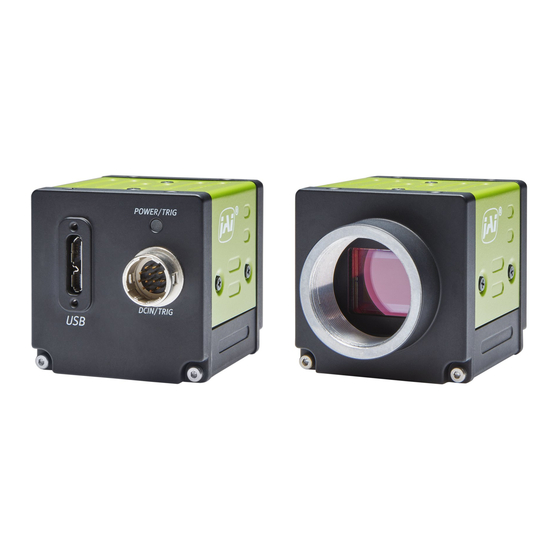
Page 7: Parts Identifications
SP-12401M-USB/SP-12401C-USB Parts Identification ② ③ ④ ① ⑤ ⑤ ① Lens mount(C-mount) Mount a C-mount lens, microscope adapter, etc. here. ❖ Before mounting a lens, be sure to refer to “Step 2:Connecting Devices” and confirm the precautions for attaching a lens and the supported lens types. - Page 8 SP-12401M-USB/SP-12401C-USB ④ DC IN/TRIG connector(12-pin round) Connect the cable for a power supply (optional) or for DC IN / trigger IN here. HR10A-10R-12PB(71)(Hirose Electric or equivalent) Pin No. Signal Description Input/Output Power In DC In DC 12 V ~ 24 V ± 10%...
- Page 9 SP-12401M-USB/SP-12401C-USB Recommended external input circuit diagram (reference example) User Side JAI Camera Side CAMERA User side side When Opto In 2 (*1) Pin4 (Opto In 2+) (*2) Pin3 (Opto In 2-) Recommended external output circuit diagram (reference example) Standard circuit diagram example...
- Page 10 SP-12401M-USB/SP-12401C-USB Characteristics of the recommended circuits for Opto OUT OUTPUT LINE RESPONSE TIME Camera Output Signal Output Line Voltage User Power (VCC) 3.3 V ~ 24 V Time Delay Rise TDR (us) 0.5 ~ 0.7 Tisc Time RT (us) 1.2 ~ 3.0 Time Delay Fall TDF (us) 1.5 ~...
-
Page 11: Preparation
When using the camera for the first time, install the software for configuring and controlling the camera (eBUS SDK for JAI) on the computer. ❖ When you install eBUS SDK for JAI, eBUS SDK for JAI player will also be installed. Download the eBUS SDK for JAI from the JAI website. -
Page 12: Step 2:Connecting Devices
SP-12401M-USB/SP-12401C-USB Step 2: Connecting Devices Camera body to external trigger ① Lens ③ USB cable ⑥ AC adapter(not supplied) (power supply) ⑤ DC IN / trigger IN ② Direct connection connection cable (or MP-45 tripod adapter plate) ④ PC ① Lens ・C-mount lenses with lens mount protrusions of 9 mm or less can be attached. - Page 13 SP-12401M-USB/SP-12401C-USB Note The following formula can be used to estimate the focal length. Focal length = WD /(1 + W/w) WD :Working distance (distance between lens and object) :Width of object :Width of sensor(14.2 mm on this camera) ② Direct connection(or MP-45 tripod adapter plate)...
-
Page 14: Step 3:Verifying Camera Operation
Step 4: Verifying the Connection between the Camera and PC Verify whether the camera is properly recognized via Control Tool. Connecting the Camera to Control Tool Startup eBUS Player for JAI eBUS Player for JAI startup screen appears. — 14 —... - Page 15 SP-12401M-USB/SP-12401C-USB Select the camera you want to configure. Push Select / Connect button The connected camera is listed. Please select one camera. — 15 —...
- Page 16 SP-12401M-USB/SP-12401C-USB Check that the settings of the selected camera are displayed. Push the Device control button. The screen shown below will be displayed. In this window you can adjust various settings of the camera. This completes the procedure for verifying whether the camera is properly recognized and whether control and settings configuration are possible.
-
Page 17: Step 5:Changing The Camera Settings
SP-12401M-USB/SP-12401C-USB Step 5: Changing the Camera Settings This section explains how to change settings by describing the procedure for changing the output format as an example. Configuring the Output Format Configure the size, position, and pixel format of the images to be acquired. -
Page 18: Step 6:Adjusting The Image Quality
SP-12401M-USB/SP-12401C-USB Step 6: Adjusting the Image Quality Display the camera image and adjust the image quality. Displaying the Image Display the image captured by the camera. When you push [Play] button, the camera image appears in right area. — 18 —... - Page 19 SP-12401M-USB/SP-12401C-USB Adjusting the Gain Adjust the image quality using the gain and white balance* functions. *) SP-12401C-USB only To adjust the image quality The Visibility must be changed from [Beginner] to [Guru]. Adjust the sensitivity via the analog gain (i.e., master gain).
-
Page 20: Step 7:Saving The Settings
*) SP-12401C-USB only Step 7: Saving the Settings The setting values configured in the player (eBUS SDK for JAI) will be deleted when the camera is turned off. By saving current setting values to user memory, you can load and recall them whenever necessary. - Page 21 SP-12401M-USB/SP-12401C-USB Select [UserSetSave], and click [Execute ‘UserSetSave’ Command]. The current setting values are saved as user settings. ■ To load user settings Stop image acquisition. User settings can only be loaded when image capture on the camera is stopped. Select the settings to load (UserSet1 to UserSet3) in [UserSetSelector].
-
Page 22: Main Functions
SP-12401M-USB/SP-12401C-USB Main Functions Basic Function Matrix The combinations of settings for the basic functions that can be used together are as follows. Sequencer 1 x 1 (Off) × ○ ○ ○ × × × 1 x 2 × ○ ○... -
Page 23: Camera Output Formats
ー ー TriggerSelector LineSelector PulseGeneratorSelector : Indicates default values for each selector. Camera Output Formats The SP-12401M-USB supports the following output formats. PixelFormat Available only VideoProcessBypassMode Mono8, Mono10, Mono10p, Mono12, Mono12, Mono12p Mono12p The SP-12401C-USB supports the following output formats. -
Page 24: Image Acquisition Controls
SP-12401M-USB/SP-12401C-USB Image Acquisition Controls Perform operations and configure settings related to image acquisition in [AcquisitionControl]. The following acquisition modes are available on the camera. AcquisitionMode Description SingleFrame Acquire a single frame when the [AcquisitionStart] command is executed. MultiFrame Acquire the number of frames specified in [AcquisitionFrameCount] when the [AcquisitionStart] command is executed. - Page 25 SP-12401M-USB/SP-12401C-USB ■ Maximum frame rate period formula About the H_Period For a full image, the H_period values are as follows for each PixelFormat. PixelFormat H_period (us) Mono8, Mono10p, Mono12p Mono10, Mono12 14.02 BayerRG8, BayerRG10p, BayerRG12p, BayerRG10, BayerRG12 14.02 BGR8, BGR10p 28.04...
-
Page 26: Exposuremode
SP-12401M-USB/SP-12401C-USB ■ When [Frame Start] trigger is [On] and [TriggerOverLap] is [Off] • Maximum frame rate of sensor output Sensor FR = 1 / {H Period × (Height_s + 36)} • Maximum frame rate by interface Interface FR = 3000 × 1000000 / (Height×Width×Pack value) •... -
Page 27: Triggercontrol
SP-12401M-USB/SP-12401C-USB Actual Exposure Times The shortest exposure times that can be configured are as follows. ExposureMode Shortest exposure time Timed 15.26us (8bit) TriggerWidth 15.26us (8bit) ・The actual exposure time will consist of the image sensor’s offset duration (14.26 μs) added to the setting configured on the camera. - Page 28 ROI (Height = 1500) 21.6ms 21.6ms 24.5ms 32.7ms 49.1ms 61.3ms ROI (Height = 750) 11.1ms 11.1ms 12.3ms 16.4ms 24.5ms 30.7ms ■ SP-12401M-USB Shortest period of trigger Mono10, Scanning range Mono8 Mono10Packed Mono12Packed Mono12 Full 42.7ms 42.7ms 49.5ms 66.0ms ROI (Height = 1500) 21.5ms...
- Page 29 SP-12401M-USB/SP-12401C-USB ■ When [ExposureMode] is [Timed] Example: When [TriggerSource] is set to [Line 5 - OptIn1] and [OptInFilterSelector] is set to [10 µs] • TriggerOverlap:Off Next trigger Input enabled* Next trigger disabled Trigger CMOS Exposure Exposure Exposure Time Active Readout...
- Page 30 SP-12401M-USB/SP-12401C-USB • TriggerOverlap:readout Next trigger Next trigger disabled Input enabled* Trigger CMOS Exposure Exposure Exposure Time Active Readout Period from trigger Period exposure end start edge to PixelFormat Line period (usec) to frame trigger wait exposure start [A] start [B] (usec)
- Page 31 SP-12401M-USB/SP-12401C-USB ■ When [ExposureMode] is [TriggerWidth] Example: When [TriggerSource] is set to [Line 5 - Optical In 1] and [OptInFilterSelector] is set to [10 µs] • TriggerOverlap:Off Next trigger input enabled* Next trigger disabled Trigger CMOS Exposure Exposure Exposure Time...
- Page 32 SP-12401M-USB/SP-12401C-USB • TriggerOverlap:readout Next trigger Next trigger disabled input enabled* Trigger CMOS Exposure Exposure Exposure Time Active Readout Period from trigger Period minimum Period trigger end Line period start edge to exposure end to PixelFormat edge to exposure (usec) exposure start [A]...
-
Page 33: Gaincontrol
SP-12401M-USB/SP-12401C-USB Gain Control Adjust the [AnalogAll] (master gain) setting first, and then adjust the [AnalogRed], [DigitalRed], [AnalogBlue], and [DigitalBlue] setting values to perform fine adjustment. *) Adjustment of DigitalRed and DigitalBlue is possible only for SP-12401C-USB Digital Blue Digital Red... -
Page 34: Lookup Table (Lut)
SP-12401M-USB/SP-12401C-USB Auto gain metering areas (16 areas) High High High High Left Mid-left Mid-right Right Mid-High Mid-High Mid-High Mid-High Left Mid-left Mid-right Right Mid-Low Mid-Low Mid-Low Mid-Low Left Mid-left Mid-right Right Left Mid-left Mid-right Right Lookup Table(LUT) The LUT function is used to generate a non-linear mapping between signal values captured on the sensor and those that are output from the camera. -
Page 35: Gamma Function
SP-12401M-USB/SP-12401C-USB Gamma Function The gamma function corrects the output signals from the camera beforehand (reverse correction), taking into consideration the light-emitting properties of the monitor display. As the light-emitting properties of the monitor are not linear, the entire image may be darker or the gradation in the dark areas may be less noticeable when camera outputs are displayed without processing. -
Page 36: Blemishcompensation
SP-12401M-USB/SP-12401C-USB BlemishCompensation Multiple defective pixels that are not adjacent to each other can occur on conventional CMOS sensor cameras. This camera features a function that interpolates defective pixels using the surrounding pixels. Up to 800 pixels can be corrected for each of the three sensors. Pixel interpolation can be performed via automatic detection or point-by-point manual settings. -
Page 37: Shadingcorrection
SP-12401M-USB/SP-12401C-USB ShadingCorrection The ShadingCorrection function corrects non-uniformity (i.e., shading) in the amount of light generated by the lens and lighting equipment. Using this function allows correction even if top, bottom, left, and right shading is not symmetrical in relation to the center of the screen (H, V). - Page 38 SP-12401M-USB/SP-12401C-USB The following shading correction modes are available on the camera. ■ FlatShading Correction is performed using the area of the screen with the highest brightness level as the reference, and adjusting the brightness levels of the other areas to match this level.
-
Page 39: Binning Function
SP-12401M-USB/SP-12401C-USB Binning Function (SP-12401M-USB only) The binning function allows you to combine the signal values of clusters of adjacent pixels to create improved virtual pixels. Using the function results in images with lower pixel resolution and higher sensitivity. ROI (Regional Scanning Function) The ROI (region of interest) function allows you to output images by specifying the areas to scan. -
Page 40: Overlap Multi Roi Mode
SP-12401M-USB/SP-12401C-USB Example 2)With Binning Example 1)Without Binning [BinningHorizontal] [BinningHorizontal] [BinningVertical] [BinningVertical] Scanning range Scanning range 2056 Width Max 4112 Width Max * For details on the frame rates for common ROI sizes, see “Frame Rate Reference” . Overlap Multi ROI Mode In Overlap Multi ROI mode, you can specify up to five scanning areas (Index 1 to 5) for a single-frame image. - Page 41 SP-12401M-USB/SP-12401C-USB Specify the areas by specifying width, height, and horizontal/vertical offset values for each index under [JAICustomControlMultiROI]. Specify an ROI in the area scanned by MultiROI Mode : On Sensor ROI and output as a separate stream. — 41 —...
-
Page 42: Sequencer Function
SP-12401M-USB/SP-12401C-USB Sequencer Function The Sequencer function lets you define up to 128 index combinations of exposure time, gain, ROI, and other settings which can be stepped through each time a trigger is received.This is particularly useful for quickly capturing multiple exposures of objects under inspection to adjust for areas or components with significantly different levels of reflectance. - Page 43 SP-12401M-USB/SP-12401C-USB Sample TriggerSequencer mode operation User-defined Indexes (up to 128) Triggers/ Image Frames Specify "1" in [SequencerSetStart], and start TriggerSequencer mode with index 1. Capture a 2-frame image with the first and second triggers. For the next index, configure index 3 specified in [SequencerSetNext], and capture an image with the number of frames (number of triggers) specified in [SequencerFrameNumber].
-
Page 44: Delayed Readout
SP-12401M-USB/SP-12401C-USB Delayed Readout Delayed readout allows images captured by a [FrameStart] trigger command to be stored temporarily inside the camera (delayed readout buffer) and read out using a [AcquisitionTransferStart] trigger after capture.This function is useful when executing triggers simultaneously on multiple cameras. -
Page 45: Color Space Conversion
BR BG BB Caution If you set the color space to XYZ or HSI, JAI Control Tool will not display the images captured by the camera properly. To display them properly, XYZ- or HSI-compatible image processing must be performed on the computer side. -
Page 46: Edge Enhancer, Color Enhancer
SP-12401M-USB/SP-12401C-USB Edge Enhancer, Color Enhancer This camera is equipped with an edge enhancer function for enhancing the contrast of lines or edges within images and a color enhancer function for enhancing specified colors. Edge enhancer function The edge enhancer function is enabled when EnhancerEnable[Edge] is set to True. Four enhancement levels are available: Low, Middle, High, and Strong. - Page 47 SP-12401M-USB/SP-12401C-USB ■ Internal camera blocks Counter0 Counter Event detection FrameStartTrigger At event occurrence or count up Counter1 Counter Event detection ExposureStart At event occurrence or count up Counter2 Counter Event detection SensorReadOut At event occurrence or count up Counter3 Counter...
-
Page 48: Videoprocessbypassmode
SP-12401M-USB/SP-12401C-USB VideoProcessBypassMode The video process bypass mode is a function that bypasses internal video processing on the camera. When bypass is enabled, the sensor output and camera output data can be set to the same bit width. 12-bit outputs can only be performed in bypass mode. -
Page 49: Setting List
SP-12401M-USB/SP-12401C-USB Setting List Feature Properties Item Setting range Default value Description a)DeviceControl Display/configure information related to the device. DeviceVendorName ー "JAI Corporation" Display the manufacturer name. DeviceModelName ー SP-12401M-USB/ Display the model name. SP-12401C-USB DeviceManufacturerInfo ー See the possibilities Display the manufacturer information. - Page 50 Display the maximum image width. BinningHorizontal 1: BinningHorizontal 1: (The values are different between 4112 4112 SP-12401M-USB and SP-12401C-USB.) BinningHorizontal 2: BinningHorizontal 2: (SP-12401M-USB : This value will vary 2056 2056 depending on the HorizontalBinning setting.) SP-12401C-PGE SP-12401C-PGE 4088 4088 HeightMax...
- Page 51 Set the pixel format. Mono8, Mono8 Mono10, Mono10p, SP-12401C-USB The following modes are enabled when Mono12, Mono12p BayerRG8 [VideoProcessBypassMode] is set to [On]. SP-12401C-USB BayerRG8, SP-12401M-USB : BayerRG10, Mono12, Mono12p BayerRG10p, BayerRG12, SP-12401C-USB : BayerRG12p, BayerRG12, BayerRG12p BGR8, BGR10p TestPattern Off, Select the test image.
- Page 52 SP-12401M-USB/SP-12401C-USB Item Setting range Default value Description c)AcquisitionControl Configure image capture settings. AcquisitionMode SingleFrame, Countinuous Select the image capture mode. MultiFrame, Continuous AcquisitionStart ー ー Start image capture. AcquisitionStop ー ー Stop image capture. AcquisitionFrameCount 1〜65535 In [MultiFrame] mode, set the number of frames to capture.
- Page 53 SP-12401M-USB/SP-12401C-USB Item Setting range Default value Description d)AnalogControl Configure analog control settings. GainSelector SP-12401M-USB AnalogAll Select the gain to configure. AnalogAll SP-12401C-USB AnalogAll, DigitalRed, DigitalBlue Gain SP-12401M-USB SP-12401M-USB Set the gain value for the gain setting AnalogAll x1.0 〜 x16.0 AnalogAll x1.0...
- Page 54 SP-12401M-USB/SP-12401C-USB Item Setting range Default value Description f)ColorTransformationControl SP-12401C-USB only ColorTransformationMode RGB, XYZ, HSI Set the output image format. ColorTransofrmationRGBMode Off, sRGB, AdobeRGB, Set the detailed mode when RGB is selected UserCustom for the color space. ColorMatrixValueSelector ColorMatrixR-R ColorMatrixR-R Select the ColorMatrix setting component.
- Page 55 SP-12401M-USB/SP-12401C-USB LineSource LineSource Select the line source signal for the item High [Line1-TTLOut1] selected in [LineSelector]. AcquisitiionTriggerWait = ExposureActive AcquisitionActive FrameTriggerWait FrameActive LineSource ExposureActive [TImestampReset] FVAL = Off LVAL PulseGenerator0 PulseGenerator1 Other default value is PulseGenerator2 Off. PulseGenerator3 UserOutput0 UserOutput1...
- Page 56 SP-12401M-USB/SP-12401C-USB Item Setting range Default value Description h)CounterAndTimerControl Configure counter settings. (This camera only supports counter functions.) CounterSelector Counter0 ー Select the counter. Counter1 Counter2 Counter3 CounterEventSource Counter0 Assign the counter event signal for which Off, FrameTrigger you want to read the count value to a Counter1 dedicated counter, and read the value.
- Page 57 SP-12401M-USB/SP-12401C-USB Item Setting range Default value Description j)SequencerControl Configure sequencer settings. SequencerMode Off, On Enable/disable [SequencerMode]. SequencerModeSelect TriggerSequencerMode, TriggerSequencerMode Select the sequencer mode. CommandSequencerMode SequencerConfigurationMode Off, On Select [On] to change the settings within the index. SequencerSetSelector 1〜128 Select the index number to configure.
- Page 58 1μs 〜 ー Set the exposure time for the selected SequencerIndex. SequencerBinningHorizontal SP-12401M-USB only For the selected SequencerIndex, set the number of pixels in the vertical direction for which to perform binning. In binning mode, the setting value of BinningHorizontalMode is applied.
- Page 59 SP-12401M-USB/SP-12401C-USB Item Setting range Default value Description k)ChunkDataControl Configure chunk control settings. ChunkModeActive True, False False Set whether to enable ChunkData. ChunkSelector OffsetX OffsetX Select the ChunkData to be added. OffsetY Width Height ExposureTime GainAnalogAll GainDigitalRed GainDigitalBlue BlackLevelDigitalAll BlackLevelDigitalRed BlackLevelDigitalBlue...
- Page 60 SP-12401M-USB/SP-12401C-USB ChunkExposureTime (us) ー ー Display the actual exposure time rather than the time set by the user. (ChunkID 2004h : DataType Float) ChunkGainAnalogAll ー ー AnalogGainAll (ChunkID 2005h : DataType Float) ChunkGainDigitalRed ー ー DigitalGainRed (ChunkID 2006h : DataType Float) ChunkGainDigitalBlue ー...
- Page 61 SP-12401M-USB/SP-12401C-USB Item Setting range Default value Description l)TestControl TestPendingAck (ms) 0〜10000 PendingAck function test command. The camera waits for TestPendingAck (ms) time and returns an Ack response. Item Setting range Default value Description m)TransportLayerControl Display information on transport layer control.
- Page 62 SP-12401M-USB/SP-12401C-USB PulseGeneratorEndPointMs 1/ PulseGeneratorClock (MHz) Set the start point of the Low interval in 〜 (ms) milliseconds. 1048575 / When the counter reaches this value, the PulseGeneratorClock (MHz) output will be 0. The setting range varies depending on the [ClockPreScaler] value.
- Page 63 SP-12401M-USB/SP-12401C-USB Item Setting range Default value Description o)JAICustomControlALC Configure JAI ALC settings. These settings are also used for AGC (auto gain control). ALCReference 30〜95 Set the target level for ALC. (unit: %) ALCAreaSelector Low Right, Low Right Select the area for which to configure Low Mid-Right, [ALCAreaEnable].
- Page 64 SP-12401M-USB/SP-12401C-USB Item Setting range Default value Description p)JAICustomControlAWB Configure AWB settings. AWBAreaSelector Low Right, Low Right Select the area for which to configure Low Mid-Right, [AWBAreaEnable]. Low Mid-Left, Low Left, Mid-Low Right, Mid-Low Mid-Right, Mid-Low Mid-Left, Mid-Low Left, Mid-High Right,...
- Page 65 SP-12401M-USB/SP-12401C-USB Item Setting range Default value Description q)JAICUstomControlBlemish Configure settings for JAI white blemish correction. BlemishEnable True, False True Enable/disable blemish correction. BlemishDetect ー ー Execute blemish detection. This command can not be executed under the following conditions. ・When no image is output ・Outputting TestPattern...
- Page 66 SP-12401M-USB/SP-12401C-USB Item Setting range Default value Description r)JAICustomControlShading Configure shading correction settings. ShadingCorrectionMode FlatShading, FlatShading Select the shading correction method. ColorShading ShadingMode Off, Set the area to which to save shading User1, correction data. User2, When this is set to [Off], shading correction User3 data is not saved.
- Page 67 SP-12401M-USB/SP-12401C-USB Item Setting range Default value Description t)JAICustomControlMisc Configure settings for other JAI functions. VideoProcessBypassMode Off, On Enable/disable VideoProcessBypass mode. EnhancerSelect SP-12401M-USB Specify the operation mode for Enhancer. Edge This function is invalid when SP-12401C-USB [ColorTransformationMode] is XYZ. Edge, Color...
-
Page 68: Miscellaneous
SP-12401M-USB/SP-12401C-USB Miscellaneous Troubleshooting Check the following before requesting help. If the problem persists, contact your local JAI distributor. ■ Power supply and connections Problem Cause and solution The POWER/TRIG LED remains lit amber and Camera initialization may not be complete does not turn green, even after power is due to lack of a network connection. -
Page 69: Specifications
SP-12401M-USB/SP-12401C-USB Specifications Item SP-12401M-USB SP-12401C-USB Scanning system Progressive scan, 1 tap Synchronization Internal Interface USB 3.0 Vision compatible Image sensor Monochrome CMOS Bayer color CMOS Image size (effective image) 1.1-inch 14.2mm(H) x 10.4mm(V) : 17.6mm(diagonal) Pixel size 3.45 μm (H) x 3.45μm(V) - Page 70 SP-12401M-USB/SP-12401C-USB Default level 33.5LSB@10bit SP-12401M-USB DigitalAll : 0 ~ 97 LSB@10bit SP-12401C-USB (PixelFormat : BGR8, BGR10p) DigitalAll : 0 ~ 97 LSB@10bit Black Level DigitalRed : 17.5 ~ 49.5 LSB @10bit Video level adjustment range adjustment DigitalBlue : 17.5 ~ 49.5 LSB @10bit...
-
Page 71: Frame Rate Reference
SP-12401M-USB/SP-12401C-USB Frame Rate Reference [Theoretical value] ■ SP-12401M-USB Pixel count Resolution Pixel size Imge size Frame rate (MP) (screen size) ROI/Binning (um) (mm) (fps @8bit) 12.37 4112 x 3008 Full pixel 3.45 x 3.45 14.19 x 10.38 (17.58) 23.4fps 3.08 2048 x 1504 3.45 x 3.45... - Page 72 SP-12401M-USB/SP-12401C-USB SP-12401C-USB Sensitivity Wave length (nm) — 72 —...
-
Page 73: Dimensions
SP-12401M-USB/SP-12401C-USB Dimensions Dimenstional tolerance: ± 0.3mm Unit: mm — 73 —... -
Page 74: Comparison Of The Decibel Display And Multiplier Display
SP-12401M-USB/SP-12401C-USB Comparison of the Decibel Display and Multiplier Display Decibels[db] Multipliers[x] Remarks 0.501 0.562 0.631 0.708 0.794 0.891 1.122 1.259 1.413 1.585 1.778 1.995 2.239 2.512 2.818 3.162 3.548 3.981 4.467 5.012 5.623 6.31 7.079 7.943 8.913 11.22 12.589 14.125 15.849... -
Page 75: User's Record
Camera type: SP-12401M-USB / SP-12401C-USB Revision: …………… Serial No: …………… Firmware version: …………… For camera revision history, please contact your local JAI distributor. Trademarks • Microsoft and Windows are trademarks or registered trademarks of Microsoft Corporation in the United States and other countries. -
Page 76: Index
SP-12401M-USB/SP-12401C-USB Index 12-pin round 8 LED 7 Lens 12 Lens mount 7 AcquisitionControl 24 LineStatus 35 Acquisition modes 24 Lookup Table 34 Adjusting the Black Level 20 LUT 34 Adjusting the Gain 19 Adjusting the White Balance 19 ALC 44... - Page 77 SP-12401M-USB/SP-12401C-USB Revision history Revision Date Changes China RoHS Jan.2021 — 77 —...
Need help?
Do you have a question about the SP-12401M-USB and is the answer not in the manual?
Questions and answers