Table of Contents
Advertisement
Quick Links
Advertisement
Table of Contents

Related Manuals for Supermicro SuperServer SYS-2029U-TN24R4T


Summary of Contents for Supermicro SuperServer SYS-2029U-TN24R4T
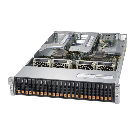
- Page 1 SuperServer ® SYS-2029U-TN24R4T USER’S MANUAL Revision 1.0g...
- Page 2 State of California, USA. The State of California, County of Santa Clara shall be the exclusive venue for the resolution of any such disputes. Supermicro's total liability for all claims will not exceed the price paid for the hardware product.
- Page 3 If you have any questions, please contact our support team at: support@supermicro.com This manual may be periodically updated without notice. Please check the Supermicro website for possible updates to the manual revision level. Secure Data Deletion A secure data deletion tool designed to fully erase all data from storage devices can be found on our website: https://www.supermicro.com/about/policies/disclaimer.cfm?url=/wdl/utility/...
-
Page 4: Table Of Contents
SuperServer SYS-2029U-TN24R4T User's Manual Contents Chapter 1 Introduction 1.1 Overview ..........................8 1.2 Unpacking the System ......................8 1.3 System Features ........................9 1.4 Chassis Features .......................10 Control Panel ........................10 Chassis Front ........................11 Chassis Rear ........................12 1.5 Motherboard Layout ......................13 Quick Reference .......................14 System Block Diagram ......................16... - Page 5 Contents Chapter 3 Maintenance and Component Installation 3.1 Removing Power ........................27 3.2 Accessing the System ......................28 3.3 Motherboard Components ....................29 Processor and Heatsink Installation ..................29 The Processor ......................29 The Processor Carrier Assembly ...................29 Overview of the Processor Heatsink Module ..............30 Creating the Processor Carrier Assembly ..............31 Assembling the Processor Heatsink Module ..............32 Preparing the CPU Socket for Installation..............33...
- Page 6 SuperServer SYS-2029U-TN24R4T User's Manual PCI Expansion Cards .......................57 Installing Full Height Expansion Cards .................58 Installing the Low Profile Center Expansion Card ............59 Chapter 4 Motherboard Connections 4.1 Power Connections ......................60 4.2 Headers and Connectors ....................61 Control Panel ........................64 4.3 Input/Output Ports ......................67 Rear I/O Ports ........................67...
- Page 7 SuperServer SYS-2029U-TN24R4T User's Manual Contacting Supermicro Contacting Supermicro Headquarters Address: Super Micro Computer, Inc. 980 Rock Ave. San Jose, CA 95131 U.S.A. Tel: +1 (408) 503-8000 Fax: +1 (408) 503-8008 Email: marketing@supermicro.com (General Information) support@supermicro.com (Technical Support) Website: www.supermicro.com Europe Address: Super Micro Computer B.V.
-
Page 8: Overview
SuperServer SYS-2029U-TN24R4T User's Manual Chapter 1 Introduction 1.1 Overview This chapter provides a brief outline of the functions and features of the SYS-2029U-TN24R4T server. It is based on the X11DPU motherboard and the SC219UB2TS-R1K62P-TN24 chassis. In addition to the motherboard and chassis, several important parts that are included with the system are listed below. -
Page 9: System Features
Dual Intel Xeon 82xx/62xx/52xx/42xx/32xx or 81xx/61xx/51xx/41xx/31xx processors (in Socket P (LGA3647)) (Intel Xeon Processor Scalable Family). For the latest CPU/memory updates, refer to our website at http://www.supermicro.com/products/motherboard/Xeon/C620/X11DPU.cfm. Memory Twenty-four slots for up to 6TB of 3DS Load Reduced DIMM (3DS LRDIMM), 3DS Registered DIMM (3DS RDIMM), or up to 3TB of Load Reduced DIMM (LRDIMM) with speeds of up to 2933 MHz;... -
Page 10: Chassis Features
SuperServer SYS-2029U-TN24R4T User's Manual 1.4 Chassis Features Control Panel Power switches and status LEDs are located on the control panel on the front of the chassis. Figure 1-1. Control Panel Control Panel Features Item Features Description The main power switch applies or removes primary power from the power supply to Power button the server but maintains standby power. -
Page 11: Chassis Front
Chapter 1: Introduction Information LED Status Description UID has been activated locally to locate the Solid blue server in a rack environment. UID has been activated using IPMI to locate the Blinking blue server in a rack environment. Chassis Front The illustration below shows the features included on the front of the chassis. -
Page 12: Chassis Rear
SuperServer SYS-2029U-TN24R4T User's Manual Chassis Rear The illustration below shows the features included on the rear of the chassis. Power supply modules display status lights. Figure 1-4. Rear View Chassis Rear Features Item Features Description Power Supply Two redundant power supply modules Four 10G Base-T RJ45 LAN ports Two USB 3.0 ports... -
Page 13: Motherboard Layout
Chapter 1: Introduction 1.5 Motherboard Layout Below is a layout of the X11DPU with jumper, connector and LED locations shown. See the table on the following page for descriptions. For detailed descriptions, pinout information and jumper settings, refer to Chapter 4. LED1 IPMI_LAN COM1... -
Page 14: Quick Reference
Chassis intrusion header NVMe SMBus (I C) headers used for PCIe hot-plug SMBus clock and data connections JNVI C1/2 (a proprietary NVMe add-on card and cable are required; available only for Supermicro complete systems) JRK1 RAID_Key for onboard NVMe devices JSD1/JSD2... - Page 15 Chapter 1: Introduction Description State: Status LED1 UID (Unit Identifier) LED Solid Blue: Unit Identified LEDM1 BMC Heartbeat LED Blinking Green: BMC Normal LEDPWR Onboard Power LED Solid Green: Power On Memory LED Description Status Memory Fault LEDs for Memory Module P1_ LED_P1_A1/LED_P1_A2 Solid Red: Memory Error A1/Memory Module P1_A2...
-
Page 16: System Block Diagram
SuperServer SYS-2029U-TN24R4T User's Manual System Block Diagram DDR4 DDR3 NCSI AST2500 IPMI LAN RTL8211F RJ45 32MB BMC UART COM1 SPI FLASH 4x 10GbE ports LPC/eSPI Ultra IO Intel SATA Port A 0~7 32MB BIOS SPI FLASH PCIe x8 Slot Drive bays... -
Page 17: Where To Get Replacement Components
(https://www.supermicro. com/support/rma/). Whenever possible, repack the chassis in the original Supermicro carton, using the original packaging material. If these are no longer available, be sure to pack the chassis securely, using packaging material to surround the chassis so that it does not shift within the carton and become damaged during shipping. -
Page 18: Chapter 2 Server Installation
SuperServer 2029U-TN24R4T User's Manual Chapter 2 Server Installation 2.1 Overview This chapter provides advice and instructions for mounting your system in a server rack. If your system is not already fully integrated with processors, system memory etc., refer to Chapter 4 for details on installing those specific components. Caution: Electrostatic Discharge (ESD) can damage electronic components. -
Page 19: Server Precautions
Chapter 2: Server Installation • In single rack installations, stabilizers should be attached to the rack. In multiple rack in- stallations, the racks should be coupled together. • Always make sure the rack is stable before extending a server or other component from the rack. -
Page 20: Circuit Overloading
SuperServer 2029U-TN24R4T User's Manual Circuit Overloading Consideration should be given to the connection of the equipment to the power supply circuitry and the effect that any possible overloading of circuits might have on overcurrent protection and power supply wiring. Appropriate consideration of equipment nameplate ratings should be used when addressing this concern. -
Page 21: Installing The Rails
Chapter 2: Server Installation 2.3 Installing the Rails There are a variety of rack units on the market, which may require a slightly different assembly procedure. This rail set fits a rack between 26.8" and 36.4" deep. The following is a basic guideline for installing the system into a rack with the rack mounting hardware provided. -
Page 22: Releasing The Inner Rail
SuperServer 2029U-TN24R4T User's Manual Releasing the Inner Rail Each inner rail has a locking latch. This latch prevents the server from coming completely out of the rack when when the chassis is pulled out for servicing. To mount the rail onto the chassis, first release the inner rail from the outer rails. 1. -
Page 23: Installing The Inner Rails On The Chassis
Chapter 2: Server Installation Installing the Inner Rails on the Chassis Installing the Inner Rails 1. Identify the left and right inner rails. They are labeled. 2. Place the inner rail firmly against the side of the chassis, aligning the hooks on the side of the chassis with the holes in the inner rail. -
Page 24: Installing The Outer Rails Onto The Rack
SuperServer 2029U-TN24R4T User's Manual Installing the Outer Rails onto the Rack Each end of the assembled outer rail includes a bracket with hooks and square, spring-loaded pegs to fit into the square holes in your rack. Installing the Outer Rail 1. -
Page 25: Installing The Chassis Into A Rack
Chapter 2: Server Installation 2.4 Installing the Chassis into a Rack Once rails are attached to the chassis and the rack, you can install the server. Warning: Mounting the system into the rack requires at least two people to support the chassis during installation. -
Page 26: Removing The Chassis From The Rack
SuperServer 2029U-TN24R4T User's Manual Removing the Chassis from the Rack Caution! The system is heavy. It is dangerous for a single person to remove it from the rack. Have sufficient personnel or use a lift to support the chassis. 1. Pull the chassis forward out the front of the rack until it stops. 2. -
Page 27: Chapter 3 Maintenance And Component Installation
Chapter 3: Maintenance and Component Installation Chapter 3 Maintenance and Component Installation This chapter provides instructions on installing and replacing main system components. To prevent compatibility issues, only use components that match the specifications and/or part numbers given. Installation or replacement of most components require that power first be removed from the system. -
Page 28: Accessing The System
SuperServer 2029U-TN24R4T User's Manual 3.2 Accessing the System The SC219AC chassis has a removable top cover to access internal components. Removing the Top Cover 1. Remove the two screws on each side of the cover, which secure the cover to the chassis. -
Page 29: Motherboard Components
Thermal grease is pre-applied on a new heatsink. No additional thermal grease is needed. • Refer to the Supermicro website for updates on processor support. • All graphics in this manual are for illustration only. Your components may look different. -
Page 30: Overview Of The Processor Heatsink Module
SuperServer 2029U-TN24R4T User's Manual Overview of the Processor Heatsink Module The Processor Heatsink Module (PHM) contains a heatsink, a processor carrier assembly. Heatsink with Thermal Grease Processor Carrier Processor Processor Heatsink Module Bottom View... -
Page 31: Creating The Processor Carrier Assembly
Chapter 3: Maintenance and Component Installation Creating the Processor Carrier Assembly To install a processor into the processor carrier, follow the steps below: 1. Hold the processor with the LGA lands (gold contacts) facing up. Locate the small, gold triangle in the corner of the processor and the corresponding hollowed triangle on the processor carrier. -
Page 32: Assembling The Processor Heatsink Module
SuperServer 2029U-TN24R4T User's Manual Assembling the Processor Heatsink Module After creating the processor carrier assembly, mount it onto the heatsink to create the processor heatsink module (PHM): 1. Note the label on top of the heatsink, which marks the heatsink mounting holes as 1, 2, 3, and 4. -
Page 33: Preparing The Cpu Socket For Installation
Chapter 3: Maintenance and Component Installation Preparing the CPU Socket for Installation This motherboard comes with a plastic protective cover on the CPU socket. Remove it carefully to install the Processor Heatsink Module (PHM). CPU Socket with Plastic Protective Cover Remove the plastic protective cover from the CPU socket. -
Page 34: Installing The Processor Heatsink Module
SuperServer 2029U-TN24R4T User's Manual Installing the Processor Heatsink Module After assembling the Processor Heatsink Module (PHM), install it onto the CPU socket: 1. Align hole 1 of the heatsink with the printed triangle on the CPU socket. See the left image below. -
Page 35: Memory
*4Gb DRAM density is only supported on speeds up to 2666 MT/s **Only the 82xx and 62xx series support 2933 MT/s; for other processors, memory speed as supported by the CPU. Check the Supermicro website for possible updates to memory support. -
Page 36: Memory Population Guidelines
Then, if using two DIMMs per channel, install the second DIMM in the black slot. The following memory population sequence table was created based on guidelines provided by Intel to support Supermicro motherboards. The diagram is for illustrative purposes; your motherboard may look different. - Page 37 Chapter 3: Maintenance and Component Installation Memory Population for the X11 DP Motherboard, 24 DIMM Slots CPUs/DIMMs Memory Population Sequence 1 CPU & 1 DIMM CPU1: P1-DIMMA1 1 CPU & 2 DIMMs CPU1: P1-DIMMA1/P1-DIMMD1 1 CPU & 3 DIMMs CPU1: P1-DIMMC1/P1-DIMMB1/P1-DIMMA1 1 CPU &...
- Page 38 SuperServer 2029U-TN24R4T User's Manual Pin 1 CPU1 CPU2 Figure 3-1a. Memory Slots...
-
Page 39: Dcpmm Population Table (24 Slots) Based On The 82Xx/62Xx/52Xx/42Xx
Chapter 3: Maintenance and Component Installation DCPMM Population Table (24 Slots) based on the 82xx/62xx/52xx/42xx Symmetric Population for Each CPU DCP & P1/P2- P1/P2- P1/P2- P1/P2- P1/P2- P1/P2- P1/P2- P1/P2- P1/P2- P1/P2- P1/P2- P1/P2- Channel Modes DIMMs DIMMF1 DIMMF2 DIMME1 DIMME2 DIMMD1 DIMMD2... - Page 40 SuperServer 2029U-TN24R4T User's Manual Notes: • For MM, general NM/FM ratio is between 1:4 and 1:16. Excessive capacity for FM can be used for AD. (NM = Near Memory; FM = Far Memory). • For each individual population, rearrangements between channels are allowed as long as the resulting population is compliant with the PDG rules for the 82xx/62xx/52xx/42xx platform.
-
Page 41: Installing Memory
Chapter 3: Maintenance and Component Installation Installing Memory ESD Precautions Electrostatic Discharge (ESD) can damage electronic com ponents including memory modules. To avoid damaging DIMM modules, it is important to handle them carefully. The following measures are generally sufficient. • Use a grounded wrist strap designed to prevent static discharge. -
Page 42: Motherboard Battery
SuperServer 2029U-TN24R4T User's Manual Motherboard Battery The motherboard uses non-volatile memory to retain system information when system power is removed. This memory is powered by a lithium battery residing on the motherboard. Replacing the Battery Begin by removing power from the system as described in section 3.1. 1. -
Page 43: Chassis Components
The server can be purchased with drives installed or without drives installed. For VROC configurations, refer to the VROC appendix in this manual. Note: Enterprise level hard disk drives are recommended for use in Supermicro chassis and servers. For information on recommended HDDs, visit the Supermicro website at https://www. -
Page 44: Front Primary Storage Drives
SuperServer 2029U-TN24R4T User's Manual Front Primary Storage Drives Removing a Hot-Swap Drive Carrier from the Chassis 1. Press the release button on the drive carrier, which will extend the drive carrier handle. 2. Use the drive carrier handle to pull the drive out of the chassis. Figure 3-3. - Page 45 Chapter 3: Maintenance and Component Installation Installing a Drive 1. Remove the dummy drive, which comes pre-installed in the drive carrier, by removing the screws securing the dummy drive to the carrier. These screws are not used to mount the actual drive. Figure 3-4.
-
Page 46: Cabling For Nvme
SuperServer 2029U-TN24R4T User's Manual Cabling for NVMe When cabling the backplane (BPN-NVME3-216A-S4) to the Ultra Riser card (AOC-2UR6N4- i4XT-P) and the NVMe add-on card card (RSC-U2N4-6), it is important to connect the proper ports. Otherwise, some NVMe drives will not be detected. BPN-NVME3-216A-S4 = 1x BPN-NVME3-216EB + 2x BPN-NVME3-216EL X11DPU RSC-U2N4-6... -
Page 47: Hot-Swap For Nvme Drives
Chapter 3: Maintenance and Component Installation Hot-Swap for NVMe Drives Supermicro Ultra servers support NVMe surprise hot-swap. For even better data security, NVMe orderly hot-swap is recommended. NVMe drives can be ejected and replaced remotely using IPMI. Note: If you are using VROC, see the VROC appendix in this manual instead. -
Page 48: Checking The Temperature Of An Nvme Drive
SuperServer 2029U-TN24R4T User's Manual Checking the Temperature of an NVMe Drive There are two ways to check using IPMI. Checking a Drive • IPMI > Server Health > NVMe SSD – Shows the temperatures of all NVMe drives, as in Figure 3-4. -
Page 49: Two Rear Auxiliary Storage Drives
Chapter 3: Maintenance and Component Installation Two Rear Auxiliary Storage Drives Two 2.5" hot-swap SATA drive bays are available on the chassis rear. These can be replaced using the same procedure as the front drives. Two SATA Drives Figure 3-7. Rear Drives M.2 Solid State Drives Up to two M.2 solid state drives (SSDs) can be installed on the RSC-UMR-8 riser card, with some restrictions. - Page 50 SuperServer 2029U-TN24R4T User's Manual Installing an M.2 SSD Caution: Use industry-standard anti-static equipment, such as gloves or wrist strap, and follow precautions to avoid damage caused by ESD. Locate the RSC-UMR-8 storage adapter card in the SXB2 slot on the motherboard. There is a plastic standoff in one of the holes.
-
Page 51: System Cooling
2. Push the release tab and pull the failed fan from the chassis. Fans can be replaced while the system is running. 3. Replace the failed fan with an identical fan, available from Supermicro. Push the new fan into the housing, making sure the air flow direction is the same. -
Page 52: Checking The Server Air Flow
SuperServer 2029U-TN24R4T User's Manual Checking the Server Air Flow • Make sure there are no objects to obstruct airflow in and out of the server. • Do not operate the server without drives or drive carriers in the drive bays. •... -
Page 53: Installing The Air Shrouds
Chapter 3: Maintenance and Component Installation Installing the Air Shrouds Air shrouds concentrate airflow to maximize fan efficiency. They do not require screws to install. If you use an M.2 SSD, a specialized shroud is installed instead of the standard shrouds. - Page 54 SuperServer 2029U-TN24R4T User's Manual Installing a Specialized Air Shroud for M.2 • Position the air shroud as illustrated in the figure below, sliding the front notch over the pin on the fan tray. Figure 3-12. Installing the M.2 Air Shroud...
-
Page 55: Power Supply
It should be replaced as soon as convenient. They can be changed without powering down the system. New units can be ordered directly from Supermicro or authorized distributors. These power supplies are auto-switching capable. This feature enables them to automatically sense the input voltage and operate at a 100-120v or 180-240v. - Page 56 SuperServer 2029U-TN24R4T User's Manual Figure 3-14. Replacing the Power Supply 4. Push the new power supply module into the power bay until it clicks. Replace with the same model. 5. Plug the AC power cord back into the module.
-
Page 57: Pci Expansion Cards
Double-width, full-height, full-length x16 (CPU2) Low-profile, half-length x8 (CPU2) Full-height = 4.2", Low-profile = 2.5" Full-length = 10.5", Half-length = 6.6" * This slot (3) supports the Supermicro SAS Cards listed below. Supermicro SAS Cards Part Number Description AOC-S3008L-L8e Std LP, 8 internal ports, 12 Gb/s per port, Gen 3,... -
Page 58: Installing Full Height Expansion Cards
SuperServer 2029U-TN24R4T User's Manual Installing Full Height Expansion Cards Riser Brackets Figure 3-16. Installing Expansion Cards Installing PCI Expansion Cards 1. Power down the system and remove the top chassis cover. 2. Remove the riser card bracket, pictured above. On the rear of the chassis, each bracket is secured by a small black plastic flip-switch with an arrow on it. -
Page 59: Installing The Low Profile Center Expansion Card
Chapter 3: Maintenance and Component Installation Installing the Low Profile Center Expansion Card Riser Card Slot Figure 3-17. Installing Low Profile Expansion Card Installing the Low Profile PCI Expansion Card 1. Power down the system and remove the top chassis cover. 2. -
Page 60: Chapter 4 Motherboard Connections
SuperServer 2029U-TN24R4T User's Manual Chapter 4 Motherboard Connections This section describes the connections on the motherboard and provides pinout definitions. Note that depending on how the system is configured, not all connections are required. The LEDs on the motherboard are also described here. A motherboard layout indicating component locations may be found in Chapter 1. -
Page 61: Headers And Connectors
Chapter 4: Motherboard Connections 4.2 Headers and Connectors Fan Headers There are eight fan headers on the motherboard. These are 4-pin fan headers, although pins 1-3 are backward compatible with traditional 3-pin fans. Four-pin fans allow fan speeds to be controlled by Thermal Management in IPMI. - Page 62 The JTPM1 header is used to connect a Trusted Platform Module (TPM)/Port 80, which is available from Supermicro. A TPM/Port 80 connector is a security device that supports encryption and authentication in hard drives. It allows the motherboard to deny access if the TPM associated with the hard drive is not installed in the system.
- Page 63 C1/2), used for PCI-E SMBus clock and data connections, provide hot-plug support thruough a dedicated SMBus interface. This feature is only available for a Supermicro complete system with a proprietary NVMe add-on card and cable installed. NVMe SMBus Header Pin Definitions...
-
Page 64: Control Panel
SuperServer 2029U-TN24R4T User's Manual Control Panel JF1 contains header pins for various control panel connections. See the figure below for the pin locations and definitions of the control panel buttons and LED indicators. All JF1 wires have been bundled into a single cable to simplify this connection. Make sure the red wire plugs into pin 1 as marked on the motherboard. - Page 65 Chapter 4: Motherboard Connections Power Fail LED The Power Fail LED connection is located on pins 5 and 6 of JF1. Power Fail LED Pin Definitions (JF1) Pin# Definition 3.3V PWR Supply Fail Overheat (OH)/Fan Fail Connect an LED cable to pins 7 and 8 of JF1 to use the Overheat/Fan Fail LED connections. The LED on pin 8 provides warnings of overheat or fan failure.
- Page 66 SuperServer 2029U-TN24R4T User's Manual Power LED The Power LED connection is located on pins 15 and 16 of JF1. Power LED Pin Definitions (JF1) Pin# Definition 3.3V Power LED NMI Button The non-maskable interrupt button header is located on pins 19 and 20 of JF1. NMI Button Pin Definitions (JF1) Pin#...
-
Page 67: Input/Output Ports
There are two LAN ports on the chassis rear provided by the Ultra add-on card. There is also a dedicated IPMI LAN port on the I/O back panel. For more information on IPMI, refer to the IPMI User's Guide posted on our website at http://www.supermicro.com. Unit Identifier Switch/UID LED Indicator A Unit Identifier (UID) switch and a UID LED indicator are located on the rear of the system. -
Page 68: Jumpers
SuperServer 2029U-TN24R4T User's Manual 4.4 Jumpers Explanation of Jumpers To modify the operation of the motherboard, jumpers are used to choose between optional settings. Jumpers create shorts between two pins to change the function associated with it. Pin 1 is identified with a square solder pad on the printed circuit board. See the motherboard layout page for jumper locations. - Page 69 Chapter 4: Motherboard Connections Watch Dog JWD controls the Watch Dog function. Watch Dog is a monitor that can reboot the system when a software application hangs. Jumping pins 1-2 will cause Watch Dog to reset the system if an application hangs. Jumping pins 2-3 will generate a non-maskable interrupt signal for the application that hangs.
-
Page 70: Led Indicators
SuperServer 2029U-TN24R4T User's Manual 4.5 LED Indicators LAN LEDs The Ethernet ports each have two LEDs. One LED indicates activity when flashing, while the other LED may be green, amber or off to indicate the speed of the connection. LAN LED (Connection Speed Indicator) LED Color... - Page 71 Chapter 4: Motherboard Connections BMC Heartbeat LED LEDM1 is the BMC heartbeat LED. When the LED is blinking green, BMC is functioning normally. Onboard Power LED Indicator LED Color Definition Green: BMC Normal Blinking Memory Fault Indication LEDs The memory fault LEDs provide visual notification to a service technician of which memory DIMM slot(s) are at fault due to un-correctable memory errors during POST (Power-On Self- Test).
-
Page 72: Storage Ports
Intel C621 chipset. In addition, it also has six S-SATA 3.0 ports (S-SATA0-3, S-SATA4/ S-SATA5) that are supported by the Intel SCU. S-SATA4/5 can be used with Supermicro SuperDOMs which are yellow SATA DOM connectors with power pins built in, and do not require external power cables. -
Page 73: Chapter 5 Software
1. Create a method to access the MS Windows installation ISO file. That can be a USB flash or media drive. 2. Retrieve the proper RST/RSTe driver. Go to the Supermicro web page for your motherboard and click on "Download the Latest Drivers and Utilities", select the proper driver, and copy it to a USB flash drive. - Page 74 SuperServer 2029U-TN24R4T User's Manual 4. During Windows Setup, continue to the dialog where you select the drives on which to install Windows. If the disk you want to use is not listed, click on “Load driver” link at the bottom left corner. Figure 5-2.
-
Page 75: Driver Installation
The Supermicro website contains drivers and utilities for your system at https://www. supermicro.com/wdl/driver. Some of these must be installed, such as the chipset driver. After accessing the website, go into the CDR_Images (in the parent directory of the above link) and locate the ISO file for your motherboard. Download this file to a USB flash or media drive. -
Page 76: Superdoctor ® 5
5.3 SuperDoctor ® The Supermicro SuperDoctor 5 is a program that functions in a command-line or web-based interface for Windows and Linux operating systems. The program monitors such system health information as CPU temperature, system voltages, system power consumption, fan speed, and provides alerts via email or Simple Network Management Protocol (SNMP). -
Page 77: Bmc
This can be found on a sticker on the chassis and a sticker on the motherboard. The sticker also displays the BMC MAC address. If necessary, the password can be reset using the Supermicro IPMICFG tool. Figure 5-5. BMC Password Label... -
Page 78: Chapter 6 Bios
SuperServer 2029U-TN24R4T User's Manual Chapter 6 BIOS 6.1 Introduction This chapter describes the AMI BIOS setup utility for the X11DPU and provides the instructions on navigating the setup screens. The BIOS is stored in a Flash EEPROM and can be updated. Note: Due to periodic changes to the BIOS, some settings may have been added or deleted since this manual was published. - Page 79 HH:MM:SS format. Note: The time is in the 24-hour format. For example, 5:30 P.M. appears as 17:30:00. The date's default value is 01/01/2016 after RTC reset. Supermicro X11DPU (Motherboard model) BIOS Version Build Date (of the BIOS) CPLD (Complex Programmable Logic Device) Version: This item displays the CPLD version used in the system.
-
Page 80: Advanced Setup Configurations
SuperServer 2029U-TN24R4T User's Manual 6.3 Advanced Setup Configurations Use the arrow keys to select the Advanced tab and press <Enter> to access the submenu items. Caution: Take caution when changing the Advanced settings. An incorrect value, a very high DRAM frequency, or an incorrect DRAM timing setting may make the system unstable. If this occurs, revert to the manufacture default settings. - Page 81 Chapter 6: BIOS Wait For "F1" If Error Use this feature to force the system to wait until the 'F1' key is pressed if an error occurs. The options are Disabled and Enabled. INT19 (Interrupt 19) Trap Response Interrupt 19 is the software interrupt that handles the boot disk function. When this item is set to Immediate, the ROM BIOS of the host adaptors will "capture"...
- Page 82 SuperServer 2029U-TN24R4T User's Manual Throttle on Power Fail Throttling improves reliability and reduces power consumption in the processor via automatic voltage control during processor idle states. Select Enabled to decrease the system power by throttling CPU frequency when one power supply is failed. The options are Disabled and Enabled.
- Page 83 Chapter 6: BIOS Intel Virtualization Technology (Available when supported by the CPU) Select Enable to use Intel® Virtualization Technology so that I/O device assignments will be reported directly to the VMM (Virtual Memory Management) through the DMAR ACPI Tables. This feature offers fully-protected I/O resource-sharing across the Intel® platforms, providing the user with greater reliability, security and availability in networking and data-sharing.
- Page 84 SuperServer 2029U-TN24R4T User's Manual Advanced Power Management Configuration CPU P State Control SpeedStep (Pstates) EIST (Enhanced Intel® SpeedStep™ Technology) allows the system to automatically adjust processor voltage and core frequency to reduce power consumption and heat dissipation. The options are Disable and Enable. EIST PSD Function This feature allows the user to change the P-State (Power-Performance State) coordina- tion type.
- Page 85 Chapter 6: BIOS Package C State Control Package C State This feature allows the user to set the limit on the C-State package register. The options are C0/C1 state, C2 state, C6 (non Retention) state, C6 (Retention) state, No Limit, and Auto.
- Page 86 SuperServer 2029U-TN24R4T User's Manual Link L1 Enable Select Enable for the QPI to enter the L1 state for power saving. The options are Dis- able, Enable, and Auto. IO Directory Cache (IODC) Use this feature to enable the IO Directory Cache (IODC) support. The options are Dis- able, Auto, Enable for Remote InvItoM Hybrid Push, InvItoM AllocFlow, Enable for Re- mote InvItoM Hybrid AllocNonAlloc, and Enable for Remote InvItoM and Remote WViLF.
- Page 87 Chapter 6: BIOS Memory Topology The following information will be displayed: P1 DIMMA1/P1 DIMMB1/P1 DIMMC1/P1 DIMMD1/P1 DIMME1/P1 DIMMF1 Memory RAS (Reliability_Availability_Serviceability) Configuration Memory RAS Configuration Setup Use this submenu to configure the following Memory RAS settings. Static Virtual Lockstep Mode Select Enable to support the static virtual lockstep mode.
- Page 88 SuperServer 2029U-TN24R4T User's Manual memory. The failing DIMM or memory rank will then be disabled. The options are Dis- able and Enable. Patrol Scrub Patrol Scrubbing is a process that allows the CPU to correct correctable memory errors detected on a memory module and send the correction to the requestor (the original source).
- Page 89 Chapter 6: BIOS PCI-E Port Link Status PCI-E Port Link Max PCI-E Port Link Speed PCI-E Port Max Payload Size Select Auto for the system BIOS to automatically set the maximum payload value for a PCI-E device to enhance system performance. The options are 128B, 256B, and Auto.
- Page 90 SuperServer 2029U-TN24R4T User's Manual RSC-UMR-8 SLOT1 Link Speed This feature allows the user to select PCI-E support for the device installed in the system. The options are Auto, Gen 1 (2.5 GT/s), Gen 2 (5 GT/s), and Gen 3 (8 GT/s).. PCI-E Port Link Status PCI-E Port Link Max PCI-E Port Link Speed...
- Page 91 Chapter 6: BIOS PCI-E Port Max Payload Size Select Auto for the system BIOS to automatically set the maximum payload value for a PCI-E device to enhance system performance. The options are 128B, 256B, and Auto. (Intel IO Acceleration) IOAT Configuration ...
- Page 92 SuperServer 2029U-TN24R4T User's Manual Posted Interrupt Use this feature to enable VT_D posted interrupt. The options are Enable and Disable. Coherency Support (Non-Isoch) Select Enable for the Non-Iscoh VT-d engine to pass through DMA (Direct Memory Access) to enhance system performance. The options are Enable and Disable. Intel®...
- Page 93 Chapter 6: BIOS Hot Plug Capable Use this feature to enable the hot plug support for PCIe root ports 3A–3D. The options are Disable and Enable. Intel® VMD for Volume Management Device on CPU2 Intel® VMD for Volume Management Device for PStack0 Select Enable to use the Intel Volume Management Device Technology for this stack.
- Page 94 SuperServer 2029U-TN24R4T User's Manual IIO-PCIE Express Global Options PCI-E Completion Timeout Disable Use this feature for PCI-E Completion Timeout support for electric tuning. The options are Yes, No, and Per-Port. South Bridge The following South Bridge information will be displayed: •...
- Page 95 Chapter 6: BIOS PCH SATA Configuration SATA Controller This item enables or disables the onboard SATA controller supported by the Intel® PCH chip The options are Disable and Enable. Configure SATA as Select AHCI to configure a SATA drive specified by the user as an AHCI drive. Select RAID to configure a SATA drive specified by the user as a RAID drive.
- Page 96 SuperServer 2029U-TN24R4T User's Manual SATA RSTe Boot Info Select Enable to provide the full int13h support for SATA controller attached devices. The options are Disable and Enable. Aggressive Link Power Management When this item is set to Enable, the SATA AHCI controller manages the power usage of the SATA link.
- Page 97 Chapter 6: BIOS SATA HDD Unlock Select Enable to unlock the HDD password. The options are Disable and Enable. Aggressive Link Power Management When this item is set to Enable, the SATA AHCI controller manages the power usage of the SATA link.
- Page 98 SuperServer 2029U-TN24R4T User's Manual • Software Preserve Support Hot Plug (sSATA Port 0~ Port 5) Select Enabled to enable a SATA port specified by the user. The options are Disable and Enable. Spin Up Device (sSATA Port 0~ Port 5) On an edge detect from 0 to 1, set this item to allow the PCH to initialize the device.
- Page 99 Chapter 6: BIOS MMCFG Base Use this feature to select the default value for the PCI MMIO (Memory-Mapped IO) base address. The options are 1G, 1.5G, 1.75G, 2G, 2.25G, and 3G. NVMe Firmware Source Use this item to select the NVMe firmware to support booting. The options are Vendor Defined Firmware and AMI Native Support.
- Page 100 SuperServer 2029U-TN24R4T User's Manual AOC-2UR6N4--i4XT NVMe1 OPROM Select which firmware will be loaded for onboard NVMe1. The options are Disabled, Legacy, and EFI. RSC-U2N4-6 NVMe1 OPROM Select which firmware will be loaded for onboard NVMe2. The options are Disabled, Legacy, and EFI.
- Page 101 Chapter 6: BIOS Serial Port 1 Configuration Serial Port 1 Configuration This submenu allows the user the configure settings of Serial Port 1. Serial Port 1 Select Enabled to enable the selected onboard serial port. The options are Disabled and Enabled.
- Page 102 SuperServer 2029U-TN24R4T User's Manual Serial Port Console Redirection COM1 Console Redirection Select Enabled to enable console redirection support for a serial port specified by the user. The options are Disabled and Enabled. *If the item above is set to Enabled, the following items will become available for user's configuration: Console Redirection Settings This feature allows the user to specify how the host computer will exchange data with the...
- Page 103 Chapter 6: BIOS Stop Bits A stop bit indicates the end of a serial data packet. Select 1 Stop Bit for standard serial data communication. Select 2 Stop Bits if slower devices are used. The options are 1 and 2. Flow Control Use this feature to set the flow control for Console Redirection to prevent data loss caused by buffer overflow.
- Page 104 SuperServer 2029U-TN24R4T User's Manual Console Redirection Settings This feature allows the user to specify how the host computer will exchange data with the client computer, which is the remote computer used by the user. Console Redirection Settings Terminal Type This feature allows the user to select the target terminal emulation type for Console Redirection.
- Page 105 Chapter 6: BIOS VT-UTF8 Combo Key Support Select Enabled to enable VT-UTF8 Combination Key support for ANSI/VT100 terminals. The options are Disabled and Enabled. Recorder Mode Select Enabled to capture the data displayed on a terminal and send it as text messages to a remote server.
- Page 106 SuperServer 2029U-TN24R4T User's Manual Console Redirection Settings This feature allows the user to specify how the host computer will exchange data with the client computer, which is the remote computer used by the user. Out-of-Band Management Port The feature selects a serial port in a client server to be used by the Windows Emergency Management Services (EMS) to communicate with a remote host server.
- Page 107 Chapter 6: BIOS High Precision Event Timer Select Enabled to activate the High Precision Event Timer (HPET) that produces periodic interrupts at a much higher frequency than a Real-time Clock (RTC) does in synchronizing multimedia streams, providing smooth playback and reducing the dependency on other timestamp calculation devices, such as an x86 RDTSC Instruction embedded in the CPU.
- Page 108 SuperServer 2029U-TN24R4T User's Manual Endorsement Hierarchy Use this item to disable or enable endorsement hierarchy for privacy control. The options are Disabled and Enabled. PH Randomization Use this feature to disable or enable Platform Hierarchy Randomization. The options are Disabled and Enabled. TXT Support Intel®...
- Page 109 Chapter 6: BIOS Cert (Certification) GUID (Global Unique Identifier) This feature displays the GUID for this system. Commit Changes and Exit Select this feature to keep the changes you have made and exit from the system. Discard Changes and Exit ...
- Page 110 SuperServer 2029U-TN24R4T User's Manual Detected DIMMs: This feature displays the number of DIMMs as detected by the system. All DIMMs are healthy. DIMMs This feature configures and displays the information of a selected DCPMM. Select a specific DIMM to view more information. DIMMs on socket 0x0000: (an example socket ID;...
- Page 111 Chapter 6: BIOS Memory controller ID Vendor ID 0x8089 Device ID 0x5141 Subsystem vendor ID 0x8089 Subsystem device ID 0x97A Device locator P1-DIMMA2 Subsystem revision ID 0x18 Interface format code 0x0301 (Non-Energy Backed Byte Addressable) Manufacturing info valid Manufacturing date 18-37 Manufacturing location 0xA2...
- Page 112 SuperServer 2029U-TN24R4T User's Manual Max average power budget [mW] 10000 Package sparing capable 1 Package sparing enabled 1 Package spares available 1 Configuration status [Valid] SKU violation ARS status [Completed] Overwrite DIMM status [Not started] Last shutdown time Fri Dec 21 17:29:23 UTC 2018 First fast refresh Viral policy enable Viral state...
- Page 113 Chapter 6: BIOS Monitor health Sensor Type [Health] Value <Healthy> Sensor Type [Controller temperature] Value <42 C> Non-critical threshold Critical lower threshold Critical upper threshold Fatal threshold State [Normal] Alarm enabled state Use this setting to establish the non-critical threshold alarm. Choices are 1 and 0. Sensor Type [Media temperature] Value <39 C>...
- Page 114 SuperServer 2029U-TN24R4T User's Manual Value <7172661 S> Sensor Type [Up time] Value <345287 S> Sensor Type [Power cycles] Value <1783> Sensor Type [FW error count] Value <8> Sensor Type [Unlatched dirty shutdown count] Value <138> Modify non-critical thresholds Controller temperature [C] 98 Media temperature [C] Percentage remaining [%] 50 Apply changes...
- Page 115 Chapter 6: BIOS State: [Disabled] Shows current state [Disabled, Frozen] Enable security Use this feature to enable security by entering a new passphrase. Press <Enter> to type in a new passphrase with at least one character. Secure erase Use this feature to erase all persistent data. The options are Yes and No Freeze lock Use this feature to prevent further lock state changes until the next reboot.
- Page 116 SuperServer 2029U-TN24R4T User's Manual DIMM ID 0x001 (an example DIMM ID; several may be available) Socket ID: 0x0001 DIMM ID: 0x1001 Memory Mode size: App Direct #1 size: 170.0 GiB App Direct #1 index: App Direct #1 settings x6 - 4KB IMC x 4KB Channel App Direct #2 size: App Direct #2 index: App Direct #2 settings...
- Page 117 Chapter 6: BIOS Delete goal config Use this to discard the region goal configuration. Namespaces Use this submenu to display, create, modify, and delete namespaces. Select a namespace to view more information. (*If a namespace has been created, it is displayed here.) NamespaceID Name Health Status.
- Page 118 SuperServer 2029U-TN24R4T User's Manual Create namespace Name Press <Enter> to type in a name of namespace. Region ID This feature displays the region ID on which to create namespace. Mode Use this feature to set namespace mode. The options are None and Sector. The op- tion, None, is for raw access only.
- Page 119 Chapter 6: BIOS Choose diagnostics type: Quick diagnostics Select Enabled to perform quick diagnostics test. The options are Disabled and Enabled. DIMM ID 0x0001 Select Enabled to enable the diagnostics procedure for this DIMM. The options are Dis- abled and Enabled. DIMM ID 0x0101 Select Enabled to enable the diagnostics procedure for this DIMM.
- Page 120 SuperServer 2029U-TN24R4T User's Manual Message: The security check succeeded. TestName: FW State: Ok Message: The firmware consistency and settings check succeeded. Preferences Use this submenu to display or modify user preferences. View and/or modify user preferences. Default DIMM ID: Use this feature to modify the default display of DIMM identifiers. The options are Handle and UID.
- Page 121 Chapter 6: BIOS Intel(R) DCPMM 1.0.0.3380 HII Driver Healthy Controller 665c5c98 Child 0 Healthy Intel(R) 10GbE Driver 7.0.19 x64 Healthy Controller 63f38f18 Child 0 Healthy Intel(R) Ethernet Controller 10 Gigabit X540-AT2 Healthy Controller 63f37398 Child 0 Healthy Intel(R) Ethernet Controller 10 Gigabit X540-AT2 Healthy Intel(R) PRO/1000 8.5.21 PCI-E Healthy...
-
Page 122: Event Logs
SuperServer 2029U-TN24R4T User's Manual 6.4 Event Logs Use this tab page to configure Event Log settings. Change SMBIOS Event Log Settings Enabling/Disabling Options SMBIOS Event Log Change this item to enable or disable all features of the SMBIOS (System Management BIOS) Event Logging during system boot. - Page 123 Chapter 6: BIOS SMBIOS Event Log Standard Settings Log System Boot Event This option toggles the System Boot Event logging to enabled or disabled. The options are Enabled and Disabled. MECI The Multiple Event Count Increment (MECI) counter counts the number of occurrences that a duplicate event must happen before the MECI counter is incremented.
-
Page 124: Ipmi
SuperServer 2029U-TN24R4T User's Manual 6.5 IPMI Use this tab page to configure Intelligent Platform Management Interface (IPMI) settings. BMC Firmware Revision This item indicates the IPMI firmware revision used in your system. IPMI STATUS (Baseboard Management Controller) This item indicates the status of the IPMI firmware installed in your system. System Event Log ... - Page 125 Chapter 6: BIOS When SEL is Full This feature allows the user to decide what the BIOS should do when the system event log is full. Select Erase Immediately to erase all events in the log when the system event log is full.
- Page 126 SuperServer 2029U-TN24R4T User's Manual Gateway IP Address This item displays the Gateway IP address for this computer. This should be in decimal and in dotted quad form (i.e., 172.31.0.1). VLAN Use this item to enable or disable the IPMI VLAN function. The options are Disable and Enable.
-
Page 127: Security
Chapter 6: BIOS 6.6 Security Use this tab page to configure Security settings. Administrator Password Press Enter to set the user password which is required to enter the BIOS setup utility. The length of the password should be from 3 characters to 20 characters long. User Password Press Enter to set the user password which is required to enter the BIOS setup utility. - Page 128 SuperServer 2029U-TN24R4T User's Manual Secure Boot Use this item to enable secure boot. The options are Disabled and Enabled. Secure Boot Mode Use this item to select the secure boot mode. The options are Standard and Custom. CSM Support Select Enabled to support the EFI Compatibility Support Module (CSM), which provides compatibility support for traditional legacy BIOS for system boot.
- Page 129 Chapter 6: BIOS Key Exchange Keys (KEK) Select Set New to load the KEK from the manufacturer's defaults. Select Append to add the KEK from the manufacturer's defaults list to the existing KEK. The default setting is Set New. Authorized Signatures ...
-
Page 130: Boot
SuperServer 2029U-TN24R4T User's Manual 6.7 Boot Use this tab page to configure Boot Settings. Boot mode select Use this item to select the type of device that the system is going to boot from. The options are LEGACY, UEFI, and DUAL. The default setting is DUAL. LEGACY to EFI support Use this item to enable the EFI boot support. - Page 131 Chapter 6: BIOS • Legacy/UEFI/Dual Boot Order #6 • Legacy/UEFI/Dual Boot Order #7 • Legacy/UEFI/Dual Boot Order #8 • UEFI/Dual Boot Order #9 • Dual Boot Order #10 • Dual Boot Order #11 • Dual Boot Order #12 • Dual Boot Order #13 •...
-
Page 132: Save & Exit
SuperServer 2029U-TN24R4T User's Manual 6.8 Save & Exit Use this tab page to configure Save & Exit settings. Save Options Discard Changes and Exit Select this option to quit the BIOS Setup without making any permanent changes to the system configuration, and reboot the computer. Select Discard Changes and Exit from the Exit menu and press <Enter>. - Page 133 Chapter 6: BIOS Listed on this section are other boot options for the system (i.e., Built-in EFI shell). Select an option and press <Enter>. Your system will boot to the selected boot option. Default Options Restore Defaults To set this feature, select Restore Optimized Defaults from the Save & Exit menu and press <Enter>.
-
Page 134: Appendix A Bios Error Codes
When BIOS performs the Power On Self Test, it writes checkpoint codes to I/O port 0080h. If the computer cannot complete the boot process, a diagnostic card can be attached to the computer to read I/O port 0080h (Supermicro p/n AOC-LPC80-20). For information on AMI updates, please refer to http://www.ami.com/products/. -
Page 135: Appendix B Standardized Warning Statements For Ac Systems
Supermicro's Technical Support department for assistance. Only certified technicians should attempt to install or configure components. Read this appendix in its entirety before installing or configuring components in the Supermicro chassis. These warnings may also be found on our website at http://www.supermicro.com/about/... - Page 136 Appendix B: Standardized Warning Statements Warnung WICHTIGE SICHERHEITSHINWEISE Dieses Warnsymbol bedeutet Gefahr. Sie befinden sich in einer Situation, die zu Verletzungen führen kann. Machen Sie sich vor der Arbeit mit Geräten mit den Gefahren elektrischer Schaltungen und den üblichen Verfahren zur Vorbeugung vor Unfällen vertraut. Suchen Sie mit der am Ende jeder Warnung angegebenen Anweisungsnummer nach der jeweiligen Übersetzung in den übersetzten Sicherheitshinweisen, die zusammen mit diesem Gerät ausgeliefert wurden.
- Page 137 SuperServer 2029U-TN24R4T User's Manual . ٌ ا ك ً ف حالة و ٌ يك أى تتسبب ف اصابة جسذ ة ٌ هذا الزهز ع ٌ خطز !تحذ ز قبل أى تعول عىل أي هعذات،يك عىل علن بالوخاطز ال ا ٌجوة عي الذوائز ٍ...
- Page 138 Appendix B: Standardized Warning Statements Warnung Vor dem Anschließen des Systems an die Stromquelle die Installationsanweisungen lesen. ¡Advertencia! Lea las instrucciones de instalación antes de conectar el sistema a la red de alimentación. Attention Avant de brancher le système sur la source d'alimentation, consulter les directives d'installation. .יש...
- Page 139 SuperServer 2029U-TN24R4T User's Manual Warnung Dieses Produkt ist darauf angewiesen, dass im Gebäude ein Kurzschluss- bzw. Überstromschutz installiert ist. Stellen Sie sicher, dass der Nennwert der Schutzvorrichtung nicht mehr als: 250 V, 20 A beträgt. ¡Advertencia! Este equipo utiliza el sistema de protección contra cortocircuitos (o sobrecorrientes) del edificio.
- Page 140 Appendix B: Standardized Warning Statements Power Disconnection Warning Warning! The system must be disconnected from all sources of power and the power cord removed from the power supply module(s) before accessing the chassis interior to install or remove system components. 電源切断の警告...
- Page 141 SuperServer 2029U-TN24R4T User's Manual يجب فصم اننظاو من جميع مصادر انطاقت وإ ز انت سهك انكهرباء من وحدة امداد انطاقت قبم انىصىل إىن امنناطق انداخهيت نههيكم نتثبيج أو إ ز انت مكىناث الجهاز 경고! 시스템에 부품들을 장착하거나 제거하기 위해서는 섀시 내부에 접근하기 전에 반드시 전원 공급장치로부터...
- Page 142 Appendix B: Standardized Warning Statements Attention Il est vivement recommandé de confier l'installation, le remplacement et la maintenance de ces équipements à des personnels qualifiés et expérimentés. !אזהרה .צוות מוסמך בלבד רשאי להתקין, להחליף את הציוד או לתת שירות עבור הציוד واملدربيه...
- Page 143 SuperServer 2029U-TN24R4T User's Manual Warnung Diese Einheit ist zur Installation in Bereichen mit beschränktem Zutritt vorgesehen. Der Zutritt zu derartigen Bereichen ist nur mit einem Spezialwerkzeug, Schloss und Schlüssel oder einer sonstigen Sicherheitsvorkehrung möglich. ¡Advertencia! Esta unidad ha sido diseñada para instalación en áreas de acceso restringido. Sólo puede obtenerse acceso a una de estas áreas mediante la utilización de una herramienta especial, cerradura con llave u otro medio de seguridad.
- Page 144 Appendix B: Standardized Warning Statements Battery Handling Warning! There is the danger of explosion if the battery is replaced incorrectly. Replace the battery only with the same or equivalent type recommended by the manufacturer. Dispose of used batteries according to the manufacturer's instructions 電池の取り扱い...
- Page 145 SuperServer 2029U-TN24R4T User's Manual هناك خطر من انفجار يف حالة اسحبذال البطارية بطريقة غري صحيحة فعليل اسحبذال البطارية فقط بنفس النىع أو ما يعادلها مام أوصث به الرشمة املصنعة جخلص من البطاريات املسحعملة وفقا لحعليامت الرشمة الصانعة 경고! 배터리가 올바르게 교체되지 않으면 폭발의 위험이 있습니다. 기존 배터리와 동일하거나 제 조사에서...
- Page 146 Appendix B: Standardized Warning Statements ¡Advertencia! Puede que esta unidad tenga más de una conexión para fuentes de alimentación. Para cortar por completo el suministro de energía, deben desconectarse todas las conexiones. Attention Cette unité peut avoir plus d'une connexion d'alimentation. Pour supprimer toute tension et tout courant électrique de l'unité, toutes les connexions d'alimentation doivent être débranchées.
- Page 147 SuperServer 2029U-TN24R4T User's Manual Backplane Voltage Warning! Hazardous voltage or energy is present on the backplane when the system is operating. Use caution when servicing. バックプレーンの電圧 システムの稼働中は危険な電圧または電力が、 バックプレーン上にかかっています。 修理する際には注意く ださい。 警告 当系统正在进行时,背板上有很危险的电压或能量,进行维修时务必小心。 警告 當系統正在進行時,背板上有危險的電壓或能量,進行維修時務必小心。 Warnung Wenn das System in Betrieb ist, treten auf der Rückwandplatine gefährliche Spannungen oder Energien auf.
- Page 148 Appendix B: Standardized Warning Statements هناك خطز مه التيار الكهزبايئ أوالطاقة املىجىدة عىل اللىحة عندما يكىن النظام يعمل كه حذ ر ا عند خدمة هذا الجهاس 경고! 시스템이 동작 중일 때 후면판 (Backplane)에는 위험한 전압이나 에너지가 발생 합니다. 서비스 작업 시 주의하십시오. Waarschuwing Een gevaarlijke spanning of energie is aanwezig op de backplane wanneer het systeem in gebruik is.
- Page 149 SuperServer 2029U-TN24R4T User's Manual תיאום חוקי החשמל הארצי !אזהרה .התקנת הציוד חייבת להיות תואמת לחוקי החשמל המקומיים והארציים تركيب املعدات الكهربائية يجب أن ميتثل للقىاويه املحلية والىطىية املتعلقة بالكهرباء 경고! 현 지역 및 국가의 전기 규정에 따라 장비를 설치해야 합니다. Waarschuwing Bij installatie van de apparatuur moet worden voldaan aan de lokale en nationale elektriciteitsvoorschriften.
- Page 150 Appendix B: Standardized Warning Statements Attention La mise au rebut ou le recyclage de ce produit sont généralement soumis à des lois et/ou directives de respect de l'environnement. Renseignez-vous auprès de l'organisme compétent. סילוק המוצר !אזהרה .סילוק סופי של מוצר זה חייב להיות בהתאם להנחיות וחוקי המדינה التخلص...
- Page 151 SuperServer 2029U-TN24R4T User's Manual Warnung Gefährlich Bewegende Teile. Von den bewegenden Lüfterblätter fern halten. Die Lüfter drehen sich u. U. noch, wenn die Lüfterbaugruppe aus dem Chassis genommen wird. Halten Sie Finger, Schraubendreher und andere Gegenstände von den Öffnungen des Lüftergehäuses entfernt.
- Page 152 Verbindungskabeln, Stromkabeln und/oder Adapater, die Ihre örtlichen Sicherheitsstandards einhalten. Der Gebrauch von anderen Kabeln und Adapter können Fehlfunktionen oder Feuer verursachen. Die Richtlinien untersagen das Nutzen von UL oder CAS zertifizierten Kabeln (mit UL/CSA gekennzeichnet), an Geräten oder Produkten die nicht mit Supermicro gekennzeichnet sind.
- Page 153 .قيرح وأ لطع يف ببستي دق ىرخأ تالوحمو تالباك يأ مادختسا .ميلسلا سباقلاو لصوملا مجح لبق نم ةدمتعملا تالباكلا مادختسا تادعملاو ةيئابرهكلا ةزهجألل ةمالسلا نوناق رظحيUL وأCSA ( ةمالع لمحت يتلاوUL/CSA) لبق نم ةددحملاو ةينعملا تاجتنملا ريغ ىرخأ تادعم يأ عمSupermicro.
- Page 154 사항을 준수하여 제공되거나 지정된 연결 혹은 구매 케이블, 전원 케이블 및 AC 어댑터를 사용하십시오. 다른 케이블이나 어댑터를 사용하면 오작동이나 화재가 발생할 수 있습니다. 전기 용품 안전법은 UL 또는 CSA 인증 케이블 (코드에 UL / CSA가 표시된 케이블)을 Supermicro 가 지정한 제품 이외의 전기 장치에 사용하는 것을 금지합니다. Stroomkabel en AC-Adapter...
-
Page 155: Appendix C System Specifications
Appendix C: System Specifications Appendix C System Specifications Processors Dual Intel Xeon 82xx/62xx/52xx/42xx/32xx or 81xx/61xx/51xx/41xx/31xx processors in a P (LGA3647) type socket Note: Please refer to the motherboard specifications pages on our website for updates to supported processors. Chipset Intel C621 chipset BIOS 128 Mb AMI Flash ROM Memory... - Page 156 SuperServer 2029U-TN24R4T User's Manual Regulatory Compliance Electromagnetic Emissions: FCC Class A, EN 55032 Class A, EN 61000-3-2/3-3, CISPR 32 Class A Electromagnetic Immunity: EN 55024/CISPR 24, (EN 61000-4-2, EN 61000-4-3, EN 61000-4-4, EN 61000-4-5, EN 61000-4-6, EN 61000-4-8, EN 61000-4-11) Other: VCCI-CISPR 32 and AS/NZS CISPR 32 Environmental: Directive 2011/65/EU and DELEGATED DIRECTIVE (EU) 2015/863 and Directive 2012/19/EU Safety: CSA/EN/IEC/UL 60950-1 Compliant, UL or CSA Listed (USA and Canada), CE Marking (Europe)
-
Page 157: Appendix D Uefi Bios Recovery
Warning: Do not upgrade the BIOS unless your system has a BIOS-related issue. Flashing the wrong BIOS can cause irreparable damage to the system. In no event shall Supermicro be liable for direct, indirect, special, incidental, or consequential damages arising from a BIOS update. - Page 158 USB device or a writable CD/DVD. Note 1: If you cannot locate the "Super.ROM" file in your drive disk, visit our website at www.supermicro.com to download the BIOS package. Extract the BIOS binary image into a USB flash device and rename it "Super.ROM" for the BIOS recovery use.
- Page 159 Appendix D: UEFI BIOS Recovery 3. After locating the healthy BIOS binary image, the system will enter the BIOS Recovery menu as shown below. Note: At this point, you may decide if you want to start the BIOS recovery. If you decide to proceed with BIOS recovery, follow the procedures below.
- Page 160 SuperServer 2029U-TN24R4T User Manual 5. After the BIOS recovery process is complete, press any key to reboot the system. 6. Using a different system, extract the BIOS package into a USB flash drive. 7. Press <Del> continuously during system boot to enter the BIOS Setup utility. From the top of the tool bar, select Boot to enter the submenu.
- Page 161 Appendix D: UEFI BIOS Recovery 8. When the UEFI Shell prompt appears, type fs# to change the device directory path. Go to the directory that contains the BIOS package you extracted earlier from Step 6. Enter flash.nsh BIOSname.### at the prompt to start the BIOS update process. Note: Do not interrupt this process until the BIOS flashing is complete.
-
Page 162: Appendix E Ipmi Crash Dump
In the event of a processor internal error (IERR) that crashes your system, you may want to provide information to support staff. You can download a crash dump of status information using IPMI. The IPMI manual is available at https://www.supermicro.com/solutions/IPMI.cfm. Check IPMI Error Log 1. - Page 163 Appendix E IPMI Crash Dump Downloading the Crash Dump File 1. In the IPMI interface, click the Miscellaneous tab, then the Trouble Shooting option. 2. Click the Dump button and wait five minutes for the file to be created. (No confirm ation message will appear.) 3.
- Page 164 Appendix F GPUs in 2U Ultra Systems Supermicro 2U Ultra systems support graphic processing units (GPUs) when installed with some additional optional parts. The GPUs have cooling requirements that can be assisted by specialized dual-level air shrouds to direct the flow from the system fans.
-
Page 165: Appendix Fgpus In 2U Ultra Systems
Appendix FGPUs in 2U Ultra Systems Screw to Chassis Side (optional) Left (WIO) Riser Bracket Ultra Riser Bracket Screw to Chassis Side (optional) Positions for GPUs Screws for Default Air Shrouds Flip-levers Figure F-2. Riser Cards and GPU Positions Adding GPUs 1. - Page 166 SuperServer 2029U-TN24R4T User's Manual Rear L Bracket for Left-side GPU Figure F-3. Inserting the Left-side GPUs into the Riser Card Bracket Rear L Bracket for Middle GPU Rear L Bracket for Right-side GPU Screw to Standoff on Chassis Floor Figure F-4. Inserting the Middle and Right-side GPUs into the Riser Card Bracket...
- Page 167 Appendix FGPUs in 2U Ultra Systems 4. Secure the front end of the GPU to the bracket with screws. For one left-side GPU, a middle GPU, or a right-side GPU the front bracket is pre-installed on the riser card bracket. Bracket for two GPUs Figure F-5.
- Page 168 SuperServer 2029U-TN24R4T User's Manual 5. Remove the two screws on the fan housing that secure the default air shrouds. (See Figure F-2) 6. Place the appropriate air shroud (see the following notes). Insert the shroud tabs into the slot at the top of the fan housing. 7.
- Page 169 Figure F-7. Installing a GPU on the Upper Left-side Notes for Installing in the Lower Left-side Position (7/8) Installation of a GPU in the 7/8 position is not supported without consultation with Supermicro due to thermal limitations. If the 7/8 position is used, mounting requires MCP-120-82904-0N...
- Page 170 SuperServer 2029U-TN24R4T User's Manual Notes for Installing in the Middle Position (2) • Break off the necessary portions of the shroud to allow for cables. In particular, remove the top row of the shroud "ramp" as labeled below. • Position the shroud as shown. The right side wall of the shroud should not cover the right- most DIMM (P1-DIMMC1).
- Page 171 Appendix FGPUs in 2U Ultra Systems Notes for Installing in the Right-side Position (1) • Break off the necessary portions of the shroud to allow for cables. • Position the shroud as shown. The right side wall of the shroud should not cover the right- most DIMM (P1-DIMMC1).
-
Page 172: Appendix G Cpu-Based Raid For Nvme
SuperServer 2029U-TN24R4T User's Manual Appendix G CPU-Based RAID for NVMe Intel Virtual RAID on CPU (Intel VROC) is an enterprise RAID solution for NVMe SSDs ® directly attached to Intel Xeon Scalable processors. Intel Volume Management Device (VMD) is an integrated controller inside the CPU PCI-E root complex. •... - Page 173 Appendix G CPU-Based RAID for NVMe Additional Information Additional information is available on the product page for the Supermicro add-on card and the linked manuals. www.supermicro.com/products/accessories/addon/AOC-VROCxxxMOD.cfm G.1 Hardware Key The Intel VROC hardware key is a license key that detects the Intel VROC SKU and activates the function accordingly.
- Page 174 SuperServer 2029U-TN24R4T User's Manual G.2 Enabling NVMe RAID RAID for NVMe SSDs must be enabled through the UEFI BIOS. 1. Install the patch as described in the Restrictions and Requirements section on a previous page. 2. Reboot the server. 3. Press [DEL] key to enter BIOS. 4.
- Page 175 Appendix G CPU-Based RAID for NVMe • For 1029U-TN10RT populated with ten U.2 NVMe drives: CPU1 Configuration CPU2 Configuration • For 2029U-TR or 2029U-E1CR populated with four U.2 NVMe drives: CPU1 Configuration CPU2 Configuration • For 2029U-TN24R4T populated with 24 U.2 NVMe drives: CPU1 Configuration CPU2 Configuration Figure G-2.
- Page 176 SuperServer 2029U-TN24R4T User's Manual 6. Press [F4] to save the configuration and reboot the system. 7. Press [DEL] to enter BIOS. 8. Switch to Advanced > Intel(R) Virtual RAID on CPU > All Intel VMD Controllers > Create RAID Volume. 9.
- Page 177 Appendix G CPU-Based RAID for NVMe G.3 Status Indications An LED indicator on the drive carrier shows the RAID status of the drive. Drive Carrier Status LED Indicator Status State (red) Normal function Locating 4 Hz blink Fault Solid on Rebuilding 1 Hz Blink IBPI SFF 8489 Defined Status LED States...
Need help?
Do you have a question about the SuperServer SYS-2029U-TN24R4T and is the answer not in the manual?
Questions and answers