Table of Contents
Advertisement
Quick Links
Advertisement
Table of Contents

Related Manuals for Atlas Copco DSS


Summary of Contents for Atlas Copco DSS
- Page 1 DSS Scroll Pump INSTRUCTION MANUAL 9824100080_A Original instructions...
- Page 2 Publication title Publication number Vacuum Pump and Vacuum Systems Safety Manual P40040100 DSS Tip seal replacement Instruction manual 9824100040 Disclaimer The content of this manual may change from time to time without notice. We accept no liability for any errors that may appear in this manual nor do we make any expressed or implied warranties regarding the content.
-
Page 3: Table Of Contents
Contents Safety and compliance..........6 1.1. - Page 4 7.2.2. Inspect the system installation....... . 26 7.2.3. Clean the exhaust silencer........27 7.2.4.
- Page 5 List of Figures Figure 1: Pump connections..........9 Figure 2: Dimensions.
-
Page 6: Safety And Compliance
Safety and compliance Safety and compliance 1.1. Definition of Warnings and Cautions NOTICE: Obligation to Provide Information Read and follow these instructions carefully before installing and commissioning to ensure optimum and safe operation right from the start. Safe and proper operation is guaranteed when used correctly and in accordance with the instructions contained in these operating instructions. -
Page 7: Safety Symbols
Safety and compliance 1.1.1. Safety symbols The safety symbols on the products shows the areas where care and attention is necessary. The safety symbols that follow are used on the product or in the product documentation. Warning/Caution An appropriate safety instruction must be followed or caution to a potential hazard exists. -
Page 8: Description
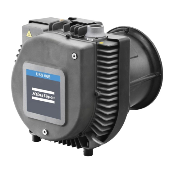
Description Description The DSS pump are rugged, reliable dry vacuum pumps designed for general vacuum use. The pumps are suitable for a wide range of industrial applications. The pump is a directly driven scroll pump and uses a standard industrial 3‑phase motor. -
Page 9: Safe Area Operation
Description Figure 1 Pump connections Exhaust silencer Exhaust silencer Pump inlet 1 1/4" BSP Pump inlet 1 1/4" BSP Pump outlet 1 1/4" BSP Pump outlet 1 1/4" BSP Blow off valve seats Blow off valve seats Secondary earthing points Secondary earthing points AV foot mount AV foot mount... -
Page 10: Technical Data
Technical data Technical data 3.1. General technical data Table 1 General technical data Parameter Data Dimensions Refer to Figure: Dimensions Weight (excluding packaging) Approximately 60 kg, 132.28 lb Maximum shaft speed Approximately 3000 rev.min Protection grade IP54* Pump inlet connection BSP 1¼”... -
Page 11: Figure 2 Dimensions
Technical data Figure 2 Dimensions Values Values Values Dimension Dimension Dimension inches inches inches 5.12 1.57 3.54 112.7 4.44 117.5 4.63 13.82 9.84 9.25 12.8 3.98 19.2 7.99 17.56 445.4 17.54 3.15 259.5 10.22 4.76 31.8 1.25 1.57 137.7 5.42 435.5 17.15 11.5... -
Page 12: Materials Of Construction
Technical data 3.2. Materials of construction Table 2 Materials of construction Component Material Fixed scroll Orbit scroll Inlet Outlet Cast aluminium Front cover Silencer curved casting Silencer with tube casting OS cover Inlet valve PBT 30% glass filled Anti‑rotation device Nylon 30% glass filled Cowl Injection moulded ‑... -
Page 13: Lubrication System
Technical data Table 4 Electrical supplies Parameter Data Pump‑electrical motor rating 1.5 kW/2 HP Fuse rating 3-phase, Type C Maximum load current ▪ 200 VD 50 Hz 7.3 A ▪ 230 VD 50 Hz 6.3 A ▪ 345 VY 50 Hz 4.2 A ▪... -
Page 14: Storage
Storage Store the pump as follows: 1. Make sure that the pump is shut down as given in Shut down the pump page 24, and disconnect the pump from the electrical supply. 2. Disconnect the pump inlet and outlet from your process and exhaust pipelines. -
Page 15: Installation
Installation Installation 5.1. Safety WARNING: INSTALLATION SAFETY Risk of injury to people and damage to equipment. Obey the safety instructions given below and take note of appropriate precautions. There must be sufficient lighting for the personnel to read all the relevant safety labels on the system. -
Page 16: Locate The Pump
Installation 1. Use a forklift truck or a pallet truck to place the pallet in a convenient position. 2. Remove the packing materials. It is recommended that you retain all packing materials for use if the pump is to be returned for service. 3. -
Page 17: Electrical Setup Of Pump
(Fuse type C). The DSS pump will start automatically when the electrical supply is turned on. If you do not want the pump to automatically restart, connect the electrical supply to the pump motor through a control equipment which must be manually reset after an electrical supply interruption. -
Page 18: Figure 3 Electrical Setup Of Pump
Installation ▪ W1 + V2 - Connected together into L2 For High voltage - Star connection (345 V - 500 V) ▪ U1 - Connect into L1 ▪ V1 - Connect into L3 ▪ W1 - Connect into L2 ▪ U2 + V2 + W2 - Connected together and insulated Change L2 with L3 for counter direction of rotation. -
Page 19: Earth (Ground) Connection
Installation ▪ 500VY 5.5. Earth (Ground) connection It is mandatory that the pump is connected to a suitable factory/plant Earth (ground) and a secondary earth grounding using the same location as shown in Figure: Secondary Earth (ground). Note: The exhaust /inlet tubes are not suitable earthing points. Figure 4 Secondary Earth (ground) Mandatory secondary earth Mandatory secondary earth... -
Page 20: Connect The Pump Inlet And Pump Outlet
Installation 2. Watch the cooling fan through a grid in the cooling air inlet, switch on the pump for one or two seconds, then switch the pump off. 3. If the cooling fan does not rotate in the correct direction shown by the arrow on the cover: Isolate the pump from the electrical supply. -
Page 21: Connect The Pump Outlet
Installation ▪ If necessary, contact us or your supplier for advice on the inlet isolation valves, outlet check valves or other components suitable for your application and system design. Procedure to connect an inlet of the pump to your process system is as follows: 1. -
Page 22: Leak Test The Installation
Installation 5.8. Leak test the installation WARNING: SYSTEM LEAKAGE Risk of injury or damage to equipment. Leak test the system after installation and maintenance. Seal any leaks found to prevent the leakage of dangerous substances out of the system and leakage of air into the system. Leak test the system after installation and seal all the leaks found. -
Page 23: Operation
Operation Operation WARNING: HOT SURFACES Risk of burns from hot surfaces. During operation, some parts of the pump become hot, these areas are identified by 'hot surface' labels. Do not touch these areas of the pump and avoid accidental contact between these areas of the pump and electrical cables and wires. -
Page 24: Startup
Operation ▪ Achieve ultimate vacuum ▪ Pump dry gases. Figure 5 Gas ballast - closed Gas ballast ON (opened in counter‑clockwise direction). Use this setting to: ▪ Pump low concentrations of condensable vapours ▪ Remove all the contamination from the pump. Figure 6 Gas ballast - open 6.1.2. -
Page 25: Maintenance
Maintenance Maintenance 7.1. Safety WARNING: MAINTENANCE SAFETY Risk of injury or damage to equipment. Obey the safety instructions given below and take note of appropriate precautions. If you do not, you can cause injury to people and damage to equipment. WARNING: HAZARDOUS VOLTAGES Risk of electric shock. -
Page 26: Maintenance Plan
Maintenance 9. Do the leak test of the system after installation is completed and seal all the leaks found to prevent leakage of dangerous substances out of the system and leakage of air into the system. See Leak test the installation on page 22. -
Page 27: Clean The Exhaust Silencer
Maintenance 3. Make sure that all the electrical connections are secure, tighten the loose connections. 7.2.3. Clean the exhaust silencer WARNING: SAFE WORKING CONDITIONS Risk of injury and damage to equipment. Follow all the safety instructions and safety precautions when you clean the exhaust silencer. Safety precautions ▪... -
Page 28: Re-Greasing The Orbit Scroll Bearings
Maintenance 6. Look through the inlet and outlet connections and inspect the visible internal surfaces (use a torch if necessary) for deposits or signs of corrosion. If the silencer is heavily contaminated or corroded, the silencer must be replaced. 7. Refit the drain plugs and replace the O-rings if damaged. 8. -
Page 29: Tip Seal Replacement
Maintenance 5. Remove the one screw which secure the Orbit scroll cover. 6. Attach the syringe with the syringe adapter firmly into the hole. Make sure that the O-ring is not damaged. 7. Push the entire content of the syringe into the hole. Apply additional force to counter the resistance. -
Page 30: Overhaul The Pump
Maintenance 7.3. Overhaul the pump We recommend that the pump is given a major overhaul in STC after 32000 hours. Such an overhaul is outside the scope of this manual and must be done by service personnel qualified by us. Contact us or your supplier for more information. -
Page 31: Fault Finding
Fault finding Fault finding Fault The pump does not operate Cause The pump is not connected to the electrical supply. Remedy The pump must be connected to a suitably fused and protected electrical supply. Cause The electrical supply voltage does not match the product requirements. Remedy Check the product label. - Page 32 Fault finding Cause There is a blockage in the exhaust line. Remedy Do the inspection of the exhaust manifold. If there are any objects or restrictions, remove it and dispose safely in accordance with all local,national safety and environmental requirements. Cause The tip seal is worn.
- Page 33 Fault finding Remedy If the pump becomes too hot, the bearings may have no grease on them. Switch off the pump immediately and contact us or your supplier. Cause There is a blockage in the exhaust line. Remedy Do the inspection of the exhaust manifold. If there are any objects or restrictions, remove them and dispose safely in accordance with all local, national safety and environmental requirements.
- Page 34 Fault finding Remedy If there is an audible regular pounding sound, the anti‑rotation device may be damaged. Switch off the pump immediately. Remove the front cover and do the inspection of the anti‑rotation device for any cracks/rupture. If you find any damage on the anti‑rotation device, contact us or your supplier.
-
Page 35: Disposal
Disposal Disposal WARNING: CONTAMINATION HAZARD Risk of toxic exposure and acid burns. Identify, contain and safely dispose of contaminated items. Dispose of the pump, cleaning solution, deposits removed from the pump, grease and any components safely, in accordance with all national and local safety and environmental regulations. -
Page 36: Spares
Spares For detailed information about the available spares, refer to parts manual 9824100045. Table 7 Spares and maintenance kits Spare / kit Item Number DSS - Field Service 1 2236232020 DSS - Bearing re-grease kit 2236232060 Exhaust silencer kit 2236232100 DSS –... -
Page 37: Service
Service Service Introduction Our products, spares and accessories are available from our companies in Belgium, Brazil, China, France, Germany, Israel, Italy, Japan, Korea, Singapore, United Kingdom, U.S.A. and a world‑wide network of distributors. The majority of these centres employ Service Engineers who have undergone our comprehensive training courses. - Page 38 Service NOTICE: If we do not receive a completed form, your equipment cannot be serviced. 9824100080_A Page 38...
- Page 39 CE Declaration of Conformity We, Atlas Copco Airpower n.v. P.O. Box 100 B-2610 Wilrijk-Antwerp Belgium Declare that the following product DSS65 230VD/400VY 50Hz 8090371503 DSS65 200VD/345VY 50Hz 8090371504 DSS65 500VY 50Hz 8090371505 Is in conformity with the relevant requirements of European CE legislation:...
- Page 40 ADDITIONAL LEGISLATION AND COMPLIANCE INFORMATION EU RoHS Directive: Material Exemption Information This product is compliant with the following Exemptions Annex III: • 6(b) Lead as an alloying element in aluminium containing up to 0.4% by weight EU REACH Regulation Compliance This product is a complex article which is not designed for intentional substance release.
- Page 41 This page has been intentionally left blank.
- Page 42 atlascopco.com...
Need help?
Do you have a question about the DSS and is the answer not in the manual?
Questions and answers