Table of Contents
Advertisement
Quick Links
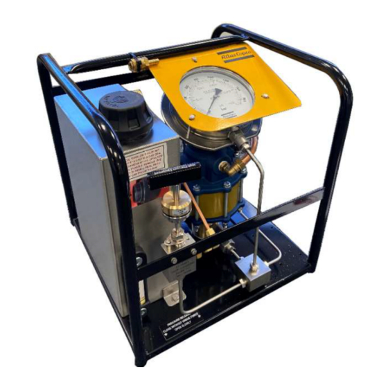
D500 HP Hydraulic Air Pump
Printed Matter No. 9839 2189 01
Publication Date 2020-09-07
Valid from Serial No. -
D500 HP Hydraulic Air Pump
Read all safety warnings and instructions
Failure to follow the safety warnings and instructions may result in
electric shock, fire and/or serious injury.
Save all warnings and instructions for future reference
8434220006
WARNING
Pneumatic Pump
Product Instructions
Advertisement
Table of Contents

Subscribe to Our Youtube Channel
Related Manuals for Atlas Copco D500


Summary of Contents for Atlas Copco D500
- Page 1 D500 HP Hydraulic Air Pump Printed Matter No. 9839 2189 01 Pneumatic Pump Publication Date 2020-09-07 Valid from Serial No. - Product Instructions D500 HP Hydraulic Air Pump 8434220006 WARNING Read all safety warnings and instructions Failure to follow the safety warnings and instructions may result in electric shock, fire and/or serious injury.
-
Page 2: Table Of Contents
Shut down procedure ................ 13 Adjustment of Pressure Release Valve (PRV) ........ 13 Service ........................ 14 Maintenance Instructions................ 14 Service Recommendations.............. 14 Lubrication Instructions................... 14 Hydraulic Fluid.................. 14 Repair Instructions.................. 15 Hydraulic Pump Seal Replacement............. 15 Troubleshooting.................... 23 Troubleshooting .................... 23 © Atlas Copco Industrial Technique AB - 9839 2189 01... -
Page 3: Product Information
■ Damage to parts that occurs as a result of inadequate maintenance or performed by parties other than Atlas Copco or their Certified Service Partners during the warranty period is not covered by the warranty. ■ To avoid damage or destruction of tool parts, service the tool according to the recommended mainte- nance schedules and follow the correct instructions. -
Page 4: Safety Data Sheets Msds/Sds
Atlas Copco air driven pump units operate on the simple but efficient principle of power magnification through the use of differential areas. A relatively large air-operated piston drives the smaller piston, which provides fluid flow at high pressures. All Atlas Copco air driven pump units are fitted into an easily trans- portable, tubular steel frame. - Page 5 D500 HP Hydraulic Air Pump Product Information If no detailed information about preventive maintenance is included, follow these general guide- lines: ■ Clean appropriate parts accurately ■ Replace any defective or worn parts © Atlas Copco Industrial Technique AB - 9839 2189 01...
-
Page 6: Installation
Setting pump stall pressure Atlas Copco supply all pump units with the air pressure regulator set to stall the pump at its maximum working pressure. Connect the main air supply to the pump unit. Slowly activate the safety On/Off... - Page 7 Operate the pump again and allow it to stall, check the pressure and further adjust if necessary. When sat- isfied that the pump stall pressure is correct the pump unit is now ready for the tensioning operation. © Atlas Copco Industrial Technique AB - 9839 2189 01...
-
Page 8: Pump Preparation
Ensure the On/Off valve is in the off position. Connect the air hose to the air inlet connector. Give the hose a sharp tug afterwards, to ensure a solid connection. © Atlas Copco Industrial Technique AB - 9839 2189 01... -
Page 9: Safety On/Off Valve
The pump unit is fitted with a safety On/Off valve. The spring loaded valve defaults to off when the valve handle is untouched. Holding the valve handle in the down position turns the pump on. Releasing the han- dle turns the pump off. © Atlas Copco Industrial Technique AB - 9839 2189 01... -
Page 10: Operation
In noisy environments, use ear protection equipment. ■ Use high-quality inserted tools and consumables to minimize exposure to excessive levels of vibra- tion. Operating Instructions Pump Operation Close the pressure release valve (clockwise). © Atlas Copco Industrial Technique AB - 9839 2189 01... - Page 11 Operation Hold down the On/Off valve. The pressure gauge will slowly indicate pressure. WARNING It is recommended that the pressure should never exceed 90% of the Gauge’s maximum pressure rating. © Atlas Copco Industrial Technique AB - 9839 2189 01...
- Page 12 Once the desired pressure is reached, release the On/Off valve. The valve will spring back to the Off position. Check the pressure reading on the oil pressure gauge. (Ensure the pressure is holding steady before approaching any pressurised bolt tensioning equipment). © Atlas Copco Industrial Technique AB - 9839 2189 01...
-
Page 13: Shut Down Procedure
Top-up the oil tank Store in pump box supplied. Adjustment of Pressure Release Valve (PRV) The PRV is factory set to vent air should the pump over pressurise. Adjustment is not necessary. © Atlas Copco Industrial Technique AB - 9839 2189 01... -
Page 14: Service
The ease of getting a proper replacement or equivalent hydraulic fluid. Example: ISO Grade 15, 32 and 68. For changing or refilling the oil, it is recommended to use the same oil as supplied with the pump. © Atlas Copco Industrial Technique AB - 9839 2189 01... -
Page 15: Repair Instructions
Hydraulic Pump Seal Replacement This section states how the internal seals within the hydraulic pump are replaced. See alsoDimensional Drawings [Page 4] of hydraulic pump. If the users have any issues, please contact Atlas Copco directly for assistance. © Atlas Copco Industrial Technique AB - 9839 2189 01... - Page 16 O-ring 11-5047N000 Bearing assembly P11000-231 O-ring P11000-028 O-ring 11-5178A000 APA valve assembly 11-5057P000 Bumper 11-5005M000 Spring 11-5060A000 Pilot valve assembly 11-5112A000 Head 11-5012N000 Bumper P11000-214 O-ring P11000-144 O-ring P10214-031 Washer-flat © Atlas Copco Industrial Technique AB - 9839 2189 01...
- Page 17 “O” rings, (Items 8 and 17), a small amount of silicone grease or other suitable lubricant should be applied. Do not remove the APA sleeve, (Item 10), from the head casting unless replacement is to be made. © Atlas Copco Industrial Technique AB - 9839 2189 01...
- Page 18 When the assembly adjustment has been done correctly, the valve will open approximately 1/32 inch when the bolt assembly is depressed to open the valve. © Atlas Copco Industrial Technique AB - 9839 2189 01...
- Page 19 Hydraulic piston 11-5010S100(195:1) Hydraulic piston 11-501OS160 (280:1) Hydraulic piston 11-5010S250(440:1) Hydraulic piston P1 1000 -1 11 O ring P 11000 -1 1 0 O ring P1 10 00-0 11 O ring © Atlas Copco Industrial Technique AB - 9839 2189 01...
- Page 20 12) and install new rubber bumper and washers(item 13 and item 11). Apply “LOCTITE” sealant to the cap screw threads when replacing and tighten securely, but not to exceed 4 Lbs.ft (5.50 Nm) max of torque. © Atlas Copco Industrial Technique AB - 9839 2189 01...
- Page 21 Repairing or Replacing the Hydraulic Check Valves Item No. Part No. Description 11-5056A000 Screw © Atlas Copco Industrial Technique AB - 9839 2189 01...
- Page 22 Bolts should be secured lightly at first then drawn up in sequence until uniform torque, 15-17 Lbs.ft (20-23 Nm) has been applied to all of the bolts around the perimeter of the pump © Atlas Copco Industrial Technique AB - 9839 2189 01...
-
Page 23: Troubleshooting
The hydraulic fluid being pumped (oil or water) may be leaking past the packing in the hydraulic cylinder into the air motor. (See also Hydraulic Pump Seal Replacement [Page 15] refer "To re- place the packing in the hydraulic cylinder" for correction procedure). © Atlas Copco Industrial Technique AB - 9839 2189 01... - Page 24 Original instructions © Copyright 2020, Atlas Copco Industrial Technique AB. All rights reserved. Any unauthorized use or copying of the contents or part thereof is prohibited. Atlas Copco Industrial This applies in particular to trademarks, model denominations, part numbers Technique AB and drawings.
Need help?
Do you have a question about the D500 and is the answer not in the manual?
Questions and answers