
Related Manuals for Atlas Copco VAR 6 250


Summary of Contents for Atlas Copco VAR 6 250
- Page 1 Instruction Manual Instruction manual for VAR Dry-Prime Centrifugal Diesel Driven Pumps English VAR 6 250 VAR 8 300 VAR 10 305 VAR 12 400...
- Page 3 Instruction manual for VAR Dry-Prime Centrifugal Diesel Driven Pumps VAR 6 250 VAR 8 300 VAR 10 305 VAR 12 400 Original instructions Printed matter N° 9829 4080 00 ATLAS COPCO - PORTABLE ENERGY DIVISION www.atlascopco.com 12/2017...
- Page 4 Neglecting maintenance or making changes to the setup of the machine can result in major hazards, including fire risk. While every effort has been made to ensure that the information in this manual is correct, Atlas Copco does not assume responsibility for possible errors.
-
Page 5: Table Of Contents
Please read the following instructions carefully before starting to use your machine. While every effort has been made to ensure that the information in this manual is correct, Atlas Copco does not assume responsibility for possible errors. Atlas Copco reserves the right to make changes without prior notice. - Page 6 Adjustments and service Disposal ........47 11.3 Critical bolt connections....66 procedures........32 11.3.1 Fastener torque of impeller nut ..66 General..........47 5.4.1 Replacing the impeller....32 11.4 Dimension drawings......67 Disposal of materials .......47 5.4.2 Replacing the front wear plate..33 11.4.1 Dimension drawing- 9829 3895 00- Circuit diagrams .
-
Page 7: Safety Precautions For Pumps
The policy of Atlas Copco is to provide the users of repair on Atlas Copco equipment. It is the unsafe operating conditions. Take necessary steps to... -
Page 8: General Safety Precautions
he manufacturer does not accept any liability for Whenever there is an indication or any suspicion 13 In the event the safety labels are damaged or any damage arising from the use of non-original that an internal part of a machine is overheated, destroyed, they must be replaced to ensure parts and for modifications, additions or conversions the machine shall be stopped but no inspection... -
Page 9: Safety During Transport And Installation
In case consult Atlas Copco. Before towing the unit: transporting a non-trailer unit on a truck, fasten 15 The electrical connections shall correspond to... -
Page 10: Safety During Use And Operation
Never refill fuel while the unit is running, unless only, vibration hazards, etc., take the necessary steps otherwise stated in the Atlas Copco Instruction - above 85 dB(A): room to be classified as a to eliminate the risk of personnel injury. -
Page 11: Safety During Maintenance And Repair
14 When washing parts in or with a cleaning 21 Whenever an abnormal condition arises, e.g. Safety during maintenance solvent, provide the required ventilation and use excessive vibration, noise, odour, etc., switch the and repair appropriate protection such as a breathing filter, circuit breakers to OFF and stop the engine. -
Page 12: Tool Applications Safety
Atlas Copco or 20 When using cartridge type breathing filter the machine manufacturer. Ascertain that the equipment, ascertain that the correct type of selected lubricants comply with all applicable cartridge is used and that its useful service life is safety regulations, especially with regard to not surpassed. -
Page 13: Battery Safety Precautions
Battery safety precautions When servicing batteries, always wear protecting clothing and glasses. The electrolyte in batteries is a sulphuric acid solution which is fatal if it hits your eyes, and which can cause burns if it contacts your skin. Therefore, be careful when handling batteries, e.g. -
Page 14: Main Parts
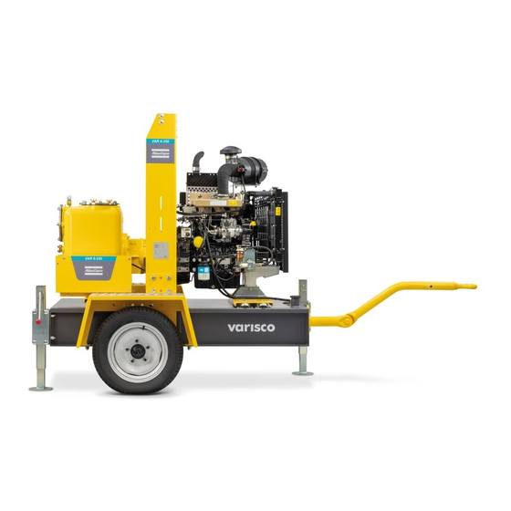
General description The VAR 6 250, VAR 8 300, VAR 10 305 and VAR 12 400 are suitable for handling clean water, dirty water or liquids up to 50°C, containing solids in suspension. The VAR 6 250, VAR 8 300, VAR 10 305 and VAR 12 400 pumps are driven by a fluid-cooled diesel engine and by air-cooled diesel engine. - Page 15 VAR 10 305 VAR 12 400 - 15 -...
- Page 16 Description Load-bearing frame (incorporates the fuel tank) Free-turning wheels Battery box Support leg (must be raised during transport) Pump drawbar Plug for draining fuel Suction pipe Delivery pipe Pump Kit lifting Engine Engine control and protection control panel Fuel level sight gauge Fuell tank filler cap Anti vibration mounting Separator...
-
Page 17: Markings
Markings Markings provide instructions and information. They also warn of hazards. For convenience and safety, keep all markings in legible condition, replacing them when damaged or missing. Replacement markings are available from the factory. A brief description of all markings provided on the pump is given hereafter. The precise location of all markings can be found in the parts manual of this pump. Indicates the presence of electric shock hazards. -
Page 18: Field Of Application
The pumps must be used only for applications for The VAR 6 250, VAR 8 300, VAR 10 305 and which the manufacturers have specified: VAR 12 400 are machine comprised of a centrifugal... -
Page 19: Engine
The non-return valve has a dual function: it prevents the suction pipe from 2.4.7 Drain plugs and filler caps emptying when the pump is off; in the event of accidental emptying of the suction The drain holes for the engine oil, the coolant and the plug for the fuel, are located pipe, this holds a sufficient amount of liquid in the pump casing to prime the pump. -
Page 20: Electrical Features
Electrical features 2.5.1 Control panel Reference Description Usage Control panel display Displays current information on screen ON-OFF switch Used to energize the unit Emergency stop button Prevents the emergency stop protection button from being pressed by- mistake Emergency stop push button Stops the machine immediately in case of emergency... -
Page 21: Installation And Connection
Installation and connection VAR 6 250 - VAR 8 300 Lifting Never use the guiding rods to lift the Before lifting the unit, check its dimensions and unit. weight, which can be found on the Data plate. When lifting the unit, the hoist has to be placed in Maximum lifting speed: Vmax . -
Page 22: Installation
– Check the tightness of the bolts and nuts. For more information about indoor installation, consult your local Atlas Copco dealer. 3.2.2 Outdoor installation – Place the pump on a horizontal, even and solid floor. The pump can operate in a slant position not exceeding 15% (in both senses: front/rear and left/right). -
Page 23: Pipework
(for larger diameter, seek Atlas Copco’s advice). Where possible, avoid curves, elbows or construction liable to limit the flow of liquid to the pump. Install the pump as near to the liquid to be pumped as possible. -
Page 24: Operating Instructions
– Check that the vacuum pump oil. the switch (2) to OFF position. – Filling the pump casing (VAR 6 250, VAR 8 300, 6. In case of emergency, press emergency stop button VAR 10 305 and VAR 12 400). -
Page 25: Priming
4.2.1 Priming If the pump does not prime, do not operate it for more than 2 minutes to avoid overheating the liquid and damaging the seal. Engine driven pumps should be brought up gradually to running speed. Never change the accelerator limit stop: at speeds higher than that for which the engine is set, the pump would absorb more power than the engine can supply. -
Page 26: Maintenance
Maintenance Maintenance schedules Before carrying out any maintenance activity, check that the start switch is in position O and that no electrical power is present on the terminals. 50 hours after initial Every 1 year or 500 Maintenance schedule Daily Every 1000 hours start-up hours... - Page 27 Replace Replace Fuel prefilter (3) (7) Replace Replace Crankcase breather filter Clean Clean Fuel filter (3) (7) Replace Replace Engine valve clearance Check/Adjust Engine turbo Check External fuel connection Check Inspection by Atlas Copco Service Technician Inspection - 27 -...
-
Page 28: Use Of Maintenance Schedule
Mechanical seal check the pump using the drain valve at the bottom of the The maintenance schedule has to be seen as a VAR 6 250, VAR 8 300, VAR 10 305 and volute. guideline for units operating in a dusty environment VAR 12 400 typical to the pump’s applications. -
Page 29: Vacuum Pump Check
VAR 6 250, VAR 8 300, VAR 10 305 and VAR 12 400 5.2.3 Vacuum pump check The mechanical seal (1) does not require maintenance during the first 500 hours of The vacuum pump is of diaphragm type; its lubrication is oil bath type. -
Page 30: Engine Oil And Oil Filter Change
– The pH-meter can be ordered from Atlas Copco – Top up the engine oil level. with part number 2913 0029 00. – Run the engine for 1 minute and check the oil –... - Page 31 – If the condition of the coolant is outside the limits, and local regulations. the complete coolant should be replaced (see – From the Atlas Copco Instruction book, determine section “Replacing the coolant”). the amount of 2954 9810 00 required and pour –...
-
Page 32: Adjustments And Service Procedures
Adjustments and service procedures 5.4.1 Replacing the impeller - 32 -... -
Page 33: Replacing The Front Wear Plate
Replacing the check valve residual liquid may be found in the Empty the pump casing. VAR 6 250, VAR 8 300, VAR 10 305 and VAR 12 400 pump casing, head and suction line. Empty the pump casing. Take the necessary precautions if the residual liquid may be found in the liquid is hazardous. -
Page 34: Replacing The Mechanical Seal
– Wash the head with solvent to remove any residue – Reassempble the casing and tighten the nuts, 5.4.4 Replacing the mechanical seal of grease and clean the seats of the stationary seal checking that the impeller is free to rotate. Empty the pump casing. -
Page 35: Replacing The Bearings
broken or damaged, replace both belts; if you only The belts used are the detachable link type; to remove 5.4.6 Replacing the bearings replace one belt, the other one will be more stretched the belt release the link, turning the head of the pin by The pump is supplied with bearings already and therefore more stressed. -
Page 36: Cleaning Cooler
5.4.8 Cleaning cooler 5.4.9 Cleaning the fuel tank 5.4.10 Battery care Before handling batteries, read the – Keep the water cooler clean to maintain the relevant safety precautions and act Observe all relevant environmental cooling efficiency. accordingly. and safety precautions. –... -
Page 37: Servicing Air Filter Engine
– Rock the battery a few times so that possible air poor cable connections or a too low voltage regulator 5.4.11 Servicing air filter engine bubbles can escape; wait 10 minutes and check the setting. level in each cell once more; if required, add 5.4.11.1 Main parts 5.4.10.5 Periodic battery service electrolyte. -
Page 38: Replacing Fuel Filter Element
5.4.11.2 Recommendation 5.4.11.4 Replacing the air filter element 5.4.12 Replacing fuel filter element – Release the snap clips (1) and remove the dust trap The Atlas Copco air filters are (2). Clean the trap. specially designed – Remove the element (4) from the housing (5). -
Page 39: Replacing Breather Filter
5.4.13 Replacing breather filter Description Cover O-ring Element Body While replacing the breather filter, also check the PCV (positive crankcase ventilation) valve: – Remove the cover (1) and element (3). – Press on the PCV valve and check that it moves smoothly. -
Page 40: Checks And Trouble Shooting
Checks and trouble Engine troubleshooting Not enough power – Restriction in a fuel pipe. shooting The table below gives an overview of the possible engine problems and their possible causes. – Fault in fuel lift pump. When a failure occurs, always –... - Page 41 – Incorrect valve tip clearances. – Fault in cold start system. The pressure of the lubricating oil is too low – Wrong grade of lubricating oil. – Engine overload. – Restriction in fuel tank vent. – Not enough lubricating oil in sump. –...
- Page 42 Crankcase pressure – Restriction in breather pipe. – Vacuum pipe leaks or fault in exhaust. Bad compression – Restriction in air filter/cleaner or induction system. – Incorrect valve tip clearances. The engine starts and stops – Dirty fuel filter element. –...
-
Page 43: Pump Troubleshooting
Make sure that the right type of suction hose has and/or strainer is correctly selected and installaded. 11. Only VAR 6 250, VAR 8 300, VAR 10 Restore or replace the vacuum pump. 305 and VAR 12 400: The vacuum pump is broken or doesn't rotate. - Page 44 12. Only VAR 6 250, VAR 8 300, VAR 10 Restore the belt tension and/or replace it 305 and VAR 12 400: Slackening or breakage of the vacuum pump drive belt. Pump does not deliver liquid 1. The pump is not primed.
-
Page 45: Residual Risks
Disassemble the casing and remove the foreign objects. Bearings do not last 1. Bearing are rusted. Change the bearings. Contact Atlas Copco Serviceability. Seal leaks 1. Seal is not working correctly. If the seal leaks during operation, it must be replaced. Contact Atlas Copco Service department. -
Page 46: Storage Of The Pump
Storage of the pump Storage Preparing for operation after storage – Store the pump in a dry, frost-free room which is well ventilated. Before operating the pump again, remove the wrapping, VCI paper and silica gel bags and check the pump thoroughly (go through the checklist “Before starting” –... -
Page 47: Disposal
Your Atlas Copco pump consists for the most part of metallic materials, that can regulations. Do not drain into the sewage system or surface water. -
Page 48: Circuit Diagrams
Circuit diagrams Circuit diagrams for VAR 6 - VAR 8 - 9829 3801 16-01 - 48 -... - Page 49 Mark Grid Name Cooalnt temp. switch Oil pressure switch Preheat Resistor Battery 12Vdc Charging Alternator Starter Relay Starter Motor Fuel solenoid hold coil Engine harness connenctor Option - 49 -...
- Page 50 9829 3801 16-02 - 50 -...
- Page 51 Mark Grid Name Controller Diode, IN5408 Diode, IN5408 Fuse 20A Fuse 5A Fuse 80A Fuse 5A LED waring light Relay Relay Relay Emergency stop switch Emergency stop switch Emergency stop switch DC power switch Speed sensor Connector Terminal Option - 51 -...
-
Page 52: Circuit Diagrams For Var 10 - Var
Circuit diagrams for VAR 10 - VAR 12 - 9829 3801 19-01 - 52 -... - Page 53 Mark Grid Name Cooalnt temp. switch Oil pressure switch Cold start temp. switch Preheat Resistor Battery 12Vdc Charging Alternator Starter Relay Starter Motor Fuel lift pump Fuel solenoid coil Cold start advance Engine harness connector - 53 -...
- Page 54 9829 3801 19 - 02 - 54 -...
- Page 55 Mark Grid Name Controller Fuse Fuse Fuse Fuse LED warning light Relay Relay Relay Relay DC breaker 50A DC breaker 50A Emergency stop switch S5b-S5d Emergency stop switch DC power switch Speed sensor Connector Terminal Option - 55 -...
-
Page 56: Wiring Harness Diagrams
Wiring Harness Diagrams 10.1 Wiring Harness Diagram- 1094 3492 00 - VAR 6 and VAR 8 - 56 -... -
Page 57: Wiring Harness Diagram- 1094 3694 00 - Var 10
10.2 Wiring Harness Diagram- 1094 3694 00 - VAR 10 - 57 -... -
Page 58: Wiring Harness Diagram- 1094 3868 00 - Var 12
10.3 Wiring Harness Diagram- 1094 3868 00 - VAR 12 - 58 -... -
Page 59: Technical Specifications
Technical specifications 11.1 Technical specifications of unit/engine/pump 11.1.1 Reference conditions Designation Unit VAR 6 VAR 8 VAR 10 VAR 12 Absolute inlet pressure bar(a) 14.5 14.5 14.5 14.5 Relative humidity Ambient air temperature °C °F Vapor Pressure Unit service duty Net Continous Net Continous Net Continous... -
Page 60: Limitations
11.1.2 Limitations Designation Unit VAR 6 VAR 8 VAR 10 VAR 12 Maximum ambient temperature at sea level °C °F Minimum starting temperature °C °F Maximim liquid temperature at sea level °C °F Maximum liquid density kg/dm³ Maximum liquid viscosity Altitude capability 4000 4000... -
Page 61: Performance Data133)
11.1.3 Performance data Designation Unit VAR 6 VAR 8 VAR 10 VAR 12 Engine/Pump shaft speed, maximum r.p.m. 2000 1200 1800 1200 Engine/Pump shaft speed, idle r.p.m. 800±50 1300±50 800±50 800±50 Operating speed r.p.m. 1200-2000 1200-1800 1200-1800 900-1200 Maximum flow m³/h 1320 Allowable operating region @maximum speed... - Page 62 Designation Unit VAR 6 VAR 8 VAR 10 VAR 12 Dimensions with optional trailer mounted. Standard fuel tank - Length 3703 4035 4875 4875 - Width 1603 1604 1754 1758 - Height 2321 2373 2520 2603 Noise Sound Pressure Level (Lp) dB(A) Measured according to (Lp) ISO 3744...
-
Page 63: Design Data
11.2 Design data 11.2.1 Engine Designation VAR 6 VAR 8 VAR 10 VAR 12 1800rpm 1600rpm 1500rpm 1000rpm Make Perkins Perkins Perkins Perkins Type 404D-22 404D-22 1104D-44T 1106D-70TA Coolant Coolant Coolant Coolant Coolant Number of cylinders Bore Stroke Swept volume 2.216 2.216 7.01... -
Page 64: Pump
11.2.2 Pump Designation VAR 6 VAR 8 VAR 10 VAR 12 Make Atlas Copco Atlas Copco Atlas Copco Atlas Copco Endurance Series, Type SIMPLE JD 6-250 SIMPLE JD 8-300 SIMPLE JD 10-305 SIMPLE JD 12-400 Pump type Centrifugal. Radial Centrifugal. Radial Centrifugal. - Page 65 REMARKS: Reference conditions for engine performance to ISO 3046-1 See D-rating diagram or consult the factory for other conditions Specific mass fuel used: 0,86 Kg/l Values obtained in reference conditions Sound pressure level referred to 7m distance Engine under exhasut emissions compliance flexibility Best efficiency point of the pump.
-
Page 66: Critical Bolt Connections
11.3 Critical bolt connections 11.3.1 Fastener torque of impeller nut THREAD FASTENER TORQUE MODEL (metric) Nm (min÷max) VAR 10 305 M30X2 37÷40 VAR 12 400 M30X2 37÷40 11.3.2. Torque setting for metric thread screws Table of tightening torques for standard screws with coarse thread 12.9 IN CONFORMITY WITH STANDARD DIN 267 Pitch... -
Page 67: Dimension Drawings
11.4 Dimension drawings 11.4.1 Dimension drawing- 9829 3895 00- VAR 6 - 67 -... -
Page 68: Dimension Drawing- 8161 0046 20- Var 8
11.4.2 Dimension drawing- 8161 0046 20- VAR 8 - 68 -... -
Page 69: Dimension Drawing- 8161 0057 75 - Var 10
11.4.3 Dimension drawing- 8161 0057 75 - VAR 10 - 69 -... -
Page 70: Dimension Drawing- 8161 0057 83 - Var 12
11.4.4 Dimension drawing- 8161 0057 83 - VAR 12 - 70 -... - Page 71 Weight values of machine Name inside varisc sap VAR 6 250 VAR SPL 8 300 VAR SPL 10 305 VAR SPL 12 400 Engine/Pump shaft speed, maximum (r.p.m.) 2000 1800 1800 1200 Operating speed (r.p.m.) 1200-2000 1200-1800 1200-1800 900-1200 Maximum flow (m...
-
Page 72: Conversion List Of Si Units Into British Units
11.5 Conversion list of SI units into British units 11.6 Data plate 1 bar 14.504 psi 0.035 oz 1 kg 2.205 lbs 1 km/h 0.621 mile/h 1 kW 1.341 hp (UK and US) 0.264 US gal 0.220 lmp gal (UK) 0.035 cu.ft 3.281 ft 1 mm... - Page 73 - 73 -...
- Page 74 A company within the Atlas Copco Group VARISCO S.p.A. Postal address Phone: +39 049 8294111 I.V.A. 00209080282 Terza Strada, 9 - Z.I. Nord Fax: +39 049 8076762 35129 PADOVA Italy For info, please contact your local Atlas Copco representative www.atlas copco.com p.1(10) - 74 -...
- Page 75 A company within the Atlas Copco Group Postal address Phone: +39 049 8294111 I.V.A. 00209080282 Terza Strada, 9 - Z.I. Nord Fax: +39 049 8076762 35129 PADOVA Italy For info, please contact your local Atlas Copco representative www.atlas copco.com p.2(10) - 75 -...
- Page 76 - 76 -...
Need help?
Do you have a question about the VAR 6 250 and is the answer not in the manual?
Questions and answers