
Related Manuals for Atlas Copco GHS 350 VSD+


Summary of Contents for Atlas Copco GHS 350 VSD+
- Page 1 Oil-Sealed Rotary Screw Vacuum Pumps series INSTRUCTION MANUAL MODEL NUMBER GHS 350 VSD+ GHS 585 VSD+ GHS 730 VSD+ GHS 900 VSD+ 6996022467_A Original instructions...
-
Page 2: Copyright Notice
It meets the requirements for instructions specified by the applicable European directives as identified in the Declaration of Conformity. Trademark credit ©2022 Atlas Copco AB, Stockholm, Sweden. Disclaimer The content of this manual may change from time to time without notice. We accept no liability for any errors that may appear in this manual nor do we make any expressed or implied warranties regarding the content. -
Page 3: Table Of Contents
3.3.3. Starting and stopping the machine......36 6996022467_A Page 3 01/2022 - ©Atlas Copco... - Page 4 8.8. Pressure switch..........84 6996022467_A Page 4 01/2022 - ©Atlas Copco...
- Page 5 Guidelines for inspection........110 6996022467_A Page 5 01/2022 - ©Atlas Copco...
- Page 6 Figure 25: Oil separator change..........84 6996022467_A Page 6 01/2022 - ©Atlas Copco...
-
Page 7: Safety And Compliance
Information about properties or instructions for an action which, if ignored, will cause damage to the equipment. We reserve the right to change the design and the stated data. The illustrations are not binding. Keep the instructions for future use. 6996022467_A Page 7 01/2022 - ©Atlas Copco... -
Page 8: General Safety Precautions
3. If the installation, operation, maintenance, and repair is done without our prior written approval, or if the pump is not installed in accordance with our recommendations, we will not accept liability or warranty claims in accordance with the standard terms and conditions. 6996022467_A Page 8 01/2022 - ©Atlas Copco... -
Page 9: Safety Precautions During Installation
Install a power isolation switch near the pump. You must be able to lock the power isolation switch. 6996022467_A Page 9 01/2022 - ©Atlas Copco... -
Page 10: Safety Precautions During Operation
For pumps without external bodywork, ear protection must be worn near the pump. 6. Persons must wear ear protection when the sound pressure level is equal to or higher than 80 dB(A). 6996022467_A Page 10 01/2022 - ©Atlas Copco... -
Page 11: Safety Precautions During Maintenance Or Repair
"Danger: The machine is remotely controlled and can start without warning." 7. Before components are removed from the pump, make sure that: ▪ the pump is isolated from all sources of under and overpressure ▪ the pump is at atmospheric pressure. 6996022467_A Page 11 01/2022 - ©Atlas Copco... - Page 12 19. Do not use caustic solvents which can damage the materials of the air net (for example, polycarbonate bowls). 20. Faults or wearing of seals can cause leakage of oil lubricant. Prevent the dispersion in soil and pollution of the other materials. 6996022467_A Page 12 01/2022 - ©Atlas Copco...
-
Page 13: General Description
The mass flow rate will decrease with a decrease in (absolute) pressure. A flow rate must be shown at a specified vacuum level when you use throughput or mass flow rate. 6996022467_A Page 13 01/2022 - ©Atlas Copco... - Page 14 Note that the distinction does not matter for a pressure difference (delta P, example, pressure loss), since it is always the result of subtracting two pressures (as absolute or gauge pressures). Our pump uses volumetric flow rate to denote the performance. 6996022467_A Page 14 01/2022 - ©Atlas Copco...
-
Page 15: Introduction
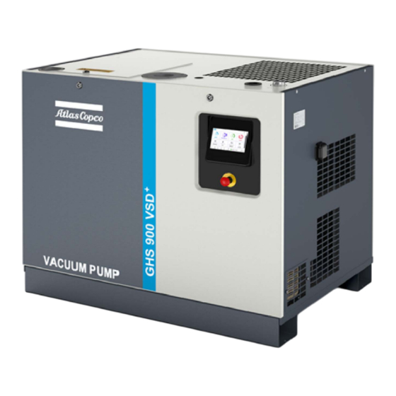
The pumps use Variable Speed Drive (VSD) technology. The VSD technology helps to automatically adjust the motor speed as necessary. The pumps are available as air‑cooled and water‑cooled. The pumps have a sound‑insulated canopy. 6996022467_A Page 15 01/2022 - ©Atlas Copco... -
Page 16: Figure 1 General View
Emergency stop button Figure 2 Front view Air intake filter Air intake filter Electric cabinet Electric cabinet Thermostatic bypass valve Thermostatic bypass valve Oil filter Oil filter Oil separator tank Oil separator tank 6996022467_A Page 16 01/2022 - ©Atlas Copco... -
Page 17: Figure 3 Rear View - Water Cooled
General description Figure 3 Rear view - Water cooled Element Element Drive motor Drive motor Water/oil cooler Water/oil cooler Figure 4 Rear view - Air cooled Cooling fan Cooling fan Air/oil cooler Air/oil cooler 6996022467_A Page 17 01/2022 - ©Atlas Copco... -
Page 18: Flow Diagram
Vacuum control valve Motor Motor Solenoid valve Solenoid valve Air filter Air filter Solenoid valve Solenoid valve Inlet filter Inlet filter Water outlet Water outlet Water inlet Water inlet Water/oil cooler Water/oil cooler 6996022467_A Page 18 01/2022 - ©Atlas Copco... -
Page 19: Figure 6 Flow Diagram Of Air Cooled Version
The air pressure pushes the oil from the oil separator tank through the oil filter. The oil cooler is bypassed. When the oil temperature increases up to 83 °C (181 °F) (87 °C (189 °F) for the optional high‑water handling capacity versions), 6996022467_A Page 19 01/2022 - ©Atlas Copco... -
Page 20: Condensate System
If the vacuum pressure decreases and the motor operates at minimum speed, the regulator stops the motor. When the motor is stopped automatically and the vacuum pressure reaches the set‑point, the regulator starts the motor again. 6996022467_A Page 20 01/2022 - ©Atlas Copco... -
Page 21: Electrical System
Figure 8 Electrical cabinet (typical example) Power supply unit Power supply unit Controller Controller Frequency converter (U1) Frequency converter (U1) Circuit breaker (Q15) Circuit breaker (Q15) Electrical diagrams You can find the electrical diagram in the electric cabinet. 6996022467_A Page 21 01/2022 - ©Atlas Copco... -
Page 22: Hex@Controller
4. To Sign-in 1. Click on Sign in button 2. Type Username and Password. 3. Click Sign in. 4. Use your login credentials or the credentials available on the sticker found on the machine. 6996022467_A Page 22 01/2022 - ©Atlas Copco... - Page 23 1. Go to the Forgot Password tab. 2. Enter the details from the controller hardware label. Viewing controller home page The default home page displays after the first login. The home page is divided into four segments 6996022467_A Page 23 01/2022 - ©Atlas Copco...
-
Page 24: Using Discovery Application For Finding The Pump
Table 1 Abbreviations HEX@ HEX@AtlasCopco controller User Interface Human Machine Interface IP address Internet Protocol address Domain Name System DHCP Dynamic Host Configuration Protocol mDNS Multicast DNS Machine to Machine MQTT Message Queuing Telemetry Transport 6996022467_A Page 24 01/2022 - ©Atlas Copco... -
Page 25: Configuring The Controller
1. Click More. 2. Navigate to Preferences > General > Units. 3. Modify the units for different parameters as per your requirement 3.2.4. Setting the date and time To set the date and time 6996022467_A Page 25 01/2022 - ©Atlas Copco... -
Page 26: Creating User Profile For Customer
Select the WiFi access point to connect. Select the Authentication mode. Enter Password. Click Connect. 6. Repeat the process for all the devices that you want to connect to the customer network through WiFi. 6996022467_A Page 26 01/2022 - ©Atlas Copco... - Page 27 Select the WiFi access point to connect. Select the Authentication mode. Enter Password. Click Connect. 6. Repeat the process for all the devices that you want to connect to the customer network through WiFi. 6996022467_A Page 27 01/2022 - ©Atlas Copco...
-
Page 28: Changing Display Settings
6. Repeat the software update. 7. If the problem persists ▪ Click on Download log. ▪ Send the log file and the software update file (if available) through TechConnect to the second level support. 6996022467_A Page 28 01/2022 - ©Atlas Copco... -
Page 29: Allowing Remote Assistance (Optional)
The Insight cards are presented on the home page and can be considered as tips to improve the pump KPI’s. 3.2.11. Checking the trend mechanism To check the trend mechanism 1. Navigate to Trends. 6996022467_A Page 29 01/2022 - ©Atlas Copco... -
Page 30: Figure 9 Checking The Trend Mechanism
3. Select the time before and after triggers as per your requirements. Modifying pump sensors on Home page To select the featured items position from Trends page on home page 1. Navigate to Trends page. 2. Click top right anchor on the tiles 6996022467_A Page 30 01/2022 - ©Atlas Copco... -
Page 31: Checking The Service Interval (Pump Maintenance)
Each interval indicates the time left before the service must performed. This can be an amount of running hours or after a fixed period. Click on a specific service interval to see additional service information. 6996022467_A Page 31 01/2022 - ©Atlas Copco... -
Page 32: Setting A Custom Digital Output Function
Indicates that the machine is performing a leak detection cycle (only available when the leak detection option is in- stalled) Indicates that the machines is running a purge cycle (pre, post or manual purge) 6996022467_A Page 32 01/2022 - ©Atlas Copco... -
Page 33: Enabling Remote Speed Control
It is possible to control the machine speed from an analog input, overwriting the machines own pressure setpoint control. The machine will limit the requested speeds in case they are outside of its allowed range. To enable remote pressure setpoint control 6996022467_A Page 33 01/2022 - ©Atlas Copco... -
Page 34: Finding The Pump Information
Operating the pump Start the pump, view the status, pressure, motor speed, and outlet temperature. Change pressure setpoints, change the mode between load-dependent or fixed- speed modes, adjust automatic restart, or set schedule actions. 6996022467_A Page 34 01/2022 - ©Atlas Copco... -
Page 35: Verifying Main Operating Conditions
1. Start/Stop icon - It is a lit up LED which indicates that the pump is in operation. 2. Mode icon - It switches the mode on the pump. A LED is lit up to indicate the active mode. 6996022467_A Page 35 01/2022 - ©Atlas Copco... -
Page 36: Starting And Stopping The Machine
Figure 14 Different colors of the start/stop button on the Controls page 3.3.4. Changing the pressure setpoint To change the pressure setpoint, proceed as follows: 1. Navigate to Settings. 2. Navigate to Pressure setpoint control. 6996022467_A Page 36 01/2022 - ©Atlas Copco... -
Page 37: Setting The Pump Modes
To add settings for the different modes 1. Click Settings > Details. 2. Add the desired settings and details. 3. Click Done. 3.3.6. Adjusting the pump settings To adjust the pump settings 1. Navigate to More. 6996022467_A Page 37 01/2022 - ©Atlas Copco... -
Page 38: Changing The Pump Mode
To change the speed control function 1. Navigate to Settings > Speed control settings. 2. Search forceMaximumSpeed. 3. Enable the Setting. The pump will always run at its maximum speed. 6996022467_A Page 38 01/2022 - ©Atlas Copco... -
Page 39: Starting The Pump Automatically After A Supply Voltage Interruption
5. Select actions (Start pump, Stop pump, Start purge, Stop purge, Change mode) based on preference. 6. Select the Interval type. If the Interval type is Timed ▪ Enter start day, time and repeat information. 6996022467_A Page 39 01/2022 - ©Atlas Copco... -
Page 40: Responding To An Alert
If the failure is solved, click on Reset pump to reset the alert. You can also see the previously solved alerts by clicking on the history button. Figure 17 Responding to an alert 6996022467_A Page 40 01/2022 - ©Atlas Copco... -
Page 41: Technical Data
Maximum permitted inlet temperature °F mbar(a) 1050 Maximum (absolute) inlet pressure psia 15.2 mbar(a) 1500 Maximum vessel pressure psia 21.8 Maximum permitted pressure of the water/oil cooler bar(a) Oil side psia 21.8 bar(a) Water side psia 6996022467_A Page 41 01/2022 - ©Atlas Copco... -
Page 42: Vacuum Pump Data
Sound pressure level (according to dB(A) 65 (±3) 65 (±3) ISO 2151 (2004)) Maximum cooling water flow L/min (cfm) 90 (3.18) 90 (3.178) Minimum cooling water flow L/min (cfm) 20 (0.71) 20 (0.71) 6996022467_A Page 42 01/2022 - ©Atlas Copco... - Page 43 L/min (cfm) 20 (0.71) 20 (0.71) Table 9 GHS 900 VSD+ With high water ha Parameter Unit Standard ndling capacity Nominal motor power Maximum motor shaft speed 7000 7000 Minimum motor shaft speed 6996022467_A Page 43 01/2022 - ©Atlas Copco...
-
Page 44: Reading On Display
- If cables are grouped together with other power cables, it can be necessary to use cables of a larger size than those calculated for the standard operating conditions. - Use the original cable entry. Refer to Figure: Dimension drawing. 6996022467_A Page 44 01/2022 - ©Atlas Copco... - Page 45 If a leakage breaker is necessary for installation, use an all current sensitive leakage breaker, RCM or RCD Type B (refer to IEC/EN 60755). Make sure that the leakage breaker has a sufficient trip level. 6996022467_A Page 45 01/2022 - ©Atlas Copco...
- Page 46 28.0 GHS 730 VSD+ 23.9 26.6 20.8 23.1 GHS 730 VSD+ 1 43.5 48.3 47.8 23.9 53.2 26.6 41.6 20.8 46.2 23.1 GHS 730 VSD+ 19.1 23.9 21.3 26.6 16.6 20.8 18.5 23.1 6996022467_A Page 46 01/2022 - ©Atlas Copco...
- Page 47 Frequency UL class K5 CSA H Recommended Pump IEC class gL/gC RC from ii cable size Wire ends (Hz) (P/FF)) GHS 350-585 VSD+ GHS 350-585 VSD+ 1 ph End sockets GHS 350-585 VSD+ 6996022467_A Page 47 01/2022 - ©Atlas Copco...
- Page 48 UL class K5 CSA H Recommended IEC class gL/gC Pump RC from ii cable size Wire ends (Hz) (P/FF)) GHS 730 VSD+ GHS 730 VSD+ 1 ph GHS 730 VSD+ End sockets GHS 900 VSD+ 6996022467_A Page 48 01/2022 - ©Atlas Copco...
- Page 49 Fuse for circuit breakers is as follows: Voltage Frequency Current Power Setting 0.48 0.48 0.46 0.46 For the pump without UL certificate, the fuse for circuit breakers is as follows: Voltage Frequency Current Power Setting 0.62 0.63 6996022467_A Page 49 01/2022 - ©Atlas Copco...
- Page 50 < 179 A < 156 A < 141 A < 127 A < 109 A 95 mm < 206 A < 179 A < 163 A < 146 A < 126 A 120 mm 6996022467_A Page 50 01/2022 - ©Atlas Copco...
- Page 51 ▪ Add 10% to the total pump current (Itot from the tables) ▪ Install the specified fuse on each cable. ▪ Parallel supply cable (2 x 3 phases + PE - configuration (2)): 6996022467_A Page 51 01/2022 - ©Atlas Copco...
- Page 52 (75 °C (167 °F)). Maximum permitted current in function of the wire size AWG or kcmil Maximum current < 30 A < 50 A < 65 A < 85 A < 100 A < 115 A 6996022467_A Page 52 01/2022 - ©Atlas Copco...
- Page 53 ▪ For AWG2/0, the maximum current is 175 A, which is sufficient => use AWG2/0 ▪ Install the specified maximum fuse (150 A) on each cable. ▪ Parallel supply cable (2 x 3 phases + 2 PE - configuration (2)): 6996022467_A Page 53 01/2022 - ©Atlas Copco...
-
Page 54: Cooling Water Requirement
This includes: ▪ selection of the correct additives ▪ selection of the correct application ▪ monitoring the concentrations and properties ▪ preventing the formation of sludge 6996022467_A Page 54 01/2022 - ©Atlas Copco... - Page 55 7.5 - 9.3 Stainless steel with carbon steel Closed loop 7.5 - 9.3 and/or cast iron Stainless steel only 6.0 - 9.3 When the system contains Zn or Al, the pH must be < 8.5. 6996022467_A Page 55 01/2022 - ©Atlas Copco...
- Page 56 ▪ B: depends on the water temperature at the outlet of the water/oil cooler ▪ C: depends on the calcium hardness (CaCO ▪ D: depends on the HCO concentration or M-alkalinity The values of A, B, C and D are given in the table that follows: 6996022467_A Page 56 01/2022 - ©Atlas Copco...
- Page 57 Do not do the disinfection with chlorine in a closed system or in a energy recovery system. Do not exceed a continuous level of 0.5 ppm. For shock treatments a maximum limit of 2 ppm for maximum 30 minutes/day applies. 6996022467_A Page 57 01/2022 - ©Atlas Copco...
- Page 58 Filter the large particles (size > 10 μm). Only the particles smaller than 5 μm can go through the filter. For the particles between 0.5 μm and 10 μm, the limits that follow are applicable. 6996022467_A Page 58 01/2022 - ©Atlas Copco...
- Page 59 Dm = ((Cpw - Cpa) * X)/(Cpw*(1-X) + X * Cpa) * 100% Where, Dm: change of mass flow of the coolant Cpw: specific heat capacity of water Cpa: specific heat capacity of the additives X: the percentage of additives 6996022467_A Page 59 01/2022 - ©Atlas Copco...
-
Page 60: Instructions For Use
▪ Only use oil as specified by the manufacturer. ▪ The vessel is guaranteed to operate for more than 20 years. ▪ The vessel needs a yearly visual inspection. 6996022467_A Page 60 01/2022 - ©Atlas Copco... -
Page 61: Installation
Antenna Customer controller connections Customer controller connections Air inlet Air inlet Air outlet Air outlet Service panel Service panel Water out R1/2" Water out R1/2" Condensate drain Condensate drain Data plate Data plate 6996022467_A Page 61 01/2022 - ©Atlas Copco... -
Page 62: Installation Proposal
Isolation of the energy sources is the responsibility of the user. The isolation valve is necessary in the installation. The electrical connection must be in accordance with all local and national safety standards. 6996022467_A Page 62 01/2022 - ©Atlas Copco... -
Page 63: Figure 19 Installation Proposal
A. Isolation valve A. Isolation valve Note: A sufficient space is necessary (1 m of clearance on all sides and top of the pump) for the safe and correct installation, daily inspection and maintenance. 6996022467_A Page 63 01/2022 - ©Atlas Copco... -
Page 64: Piping
1 ph is 32 °C (90 °F), (minimum 0 °C / 32 °F). Refer to for ventilation alternatives. The ventilation alternative 1 and 3: The necessary ventilation to limit the pump room temperature is calculated from: Qv = SF * Pnom / (1.21 * dT) 6996022467_A Page 64 01/2022 - ©Atlas Copco... -
Page 65: Position The Pump
▪ Make sure that the beams do not slide and extend uniformly from the frame. ▪ Hold the chains parallel to the bodywork by the chain spreaders to prevent damage to the pump. 6996022467_A Page 65 01/2022 - ©Atlas Copco... -
Page 66: Acclimatization
To use the pump in light industrial, commercial or residential environments with a shared supply network, or in an IT network, extra precautions are necessary. Contact us for information. 6996022467_A Page 66 01/2022 - ©Atlas Copco... -
Page 67: Figure 21 Service Diagram
Stop the pump and switch off the voltage before external equipment is connected. Only potential‑free contacts are permitted. Figure 21 Service diagram Customer’s installation Customer’s installation Pump motor Pump motor You can find the electrical diagram in the electric cabinet. 6996022467_A Page 67 01/2022 - ©Atlas Copco... -
Page 68: Pictographs
If the rotation direction is wrong, open the isolating switch in the voltage the isolating switch in the voltage supply line and reverse the two supply line and reverse the two incoming electric lines. incoming electric lines. 6996022467_A Page 68 01/2022 - ©Atlas Copco... -
Page 69: Operation
12. Check the oil level. The oil level must reach the top of the oil sight glass. 13. If necessary, fill the oil through the oil filler plug. 14. Make sure that no dirt enters the oil system. 6996022467_A Page 69 01/2022 - ©Atlas Copco... -
Page 70: Start The Pump
When the automatic operation LED is on, the pump can start automatically. When the automatic operation LED is on, the controller controls the pump, for example, to load, stop and restart the motors. Regularly check the oil level during the operation. 6996022467_A Page 70 01/2022 - ©Atlas Copco... -
Page 71: Stop The Pump
5. Use the Scroll keys to move the cursor to the Stop icon. 6. Push the Enter key. 7. Push Reset icon. 8. Close the air isolation valve. 9. Set the voltage to off. 6996022467_A Page 71 01/2022 - ©Atlas Copco... -
Page 72: Taking Out Of Operation
1. Set the electrical supply to off. 2. Shut off the system connected to the pump. 3. Open the vent plug and release the compressed gases. 4. Isolate the pump from the pump system. 5. Drain the oil. 6996022467_A Page 72 01/2022 - ©Atlas Copco... -
Page 73: Maintenance
84. Service contracts We offer different types of service contracts, to relieve you of all preventive maintenance work. Contact our customer centre. General Replace the O-rings and washers that are removed during servicing. 6996022467_A Page 73 01/2022 - ©Atlas Copco... - Page 74 Check for possible air and oil leakages Check coolers, clean if necessary Check the filter elements of the electric cabi- net. Replace if necessary 3-Monthly 3-Monthly 3-Monthly Check the silencer of the vacuum control valve, clean if necessary 6996022467_A Page 74 01/2022 - ©Atlas Copco...
- Page 75 48000 hours 36000 hours ‡ Element overhaul for mineral oil Working pressure, P ≥ 300 mbar(a) 72000 hours 60000 hours 48000 hours Working pressure, P ≥ 200 mbar(a) 64000 hours 48000 hours 32000 hours 6996022467_A Page 75 01/2022 - ©Atlas Copco...
- Page 76 2 year more than 40 °C more than 110 °C 6000 hours 2 year * Exchange interval hours based on normal application. Note: Contact us if it is necessary to change the timer setting. 6996022467_A Page 76 01/2022 - ©Atlas Copco...
-
Page 77: Oil Specification
0 °C (32 °F) and 40 °C (104 °F). If the pumps regularly operates in the ambient temperatures more than 35 °C (95 °F), the oil lifetime decreases. 6996022467_A Page 77 01/2022 - ©Atlas Copco... -
Page 78: Drive Motor
7. Install the cover of the air filter. 8. Set the air filter service warning again. Note: When you install the air filter element, make sure that the seal is in good condition. 6996022467_A Page 78 01/2022 - ©Atlas Copco... -
Page 79: Figure 23 Air Filter
Maintenance Figure 23 Air filter Inlet air filter Inlet air filter Plug Plug Air filter gas ballast Air filter gas ballast 6996022467_A Page 79 01/2022 - ©Atlas Copco... -
Page 80: Oil And Oil Filter Change
4. Vent the pump by opening the plug on the cover of the air inlet filter. 5. Remove the vent plug of the oil cooler. 1. Vent plug 2. Water/oil cooler 3. Air/oil cooler 4. Vent plug 6996022467_A Page 80 01/2022 - ©Atlas Copco... - Page 81 13. Remove the plug in the outlet element housing and drain the oil from the pump element and outlet housing. 14. Collect the oil in a collector and deliver it to the local collection service. 6996022467_A Page 81 01/2022 - ©Atlas Copco...
-
Page 82: Coolers
Risk of damage to equipment. Remove the loose parts that are used as a cover after the maintenance on the fan and on the cooler. Remove the water inside water/oil cooler if there is a risk of freezing. 6996022467_A Page 82 01/2022 - ©Atlas Copco... -
Page 83: Oil Separator Change
An arrow is given on the cover of the separator elements and at the bottom of the shield. All arrows must point in the same direction after the installation. To remove the oil separator: 1. Stop the pump. 6996022467_A Page 83 01/2022 - ©Atlas Copco... -
Page 84: Pressure Switch
8.9. Service kits For overhaul and for the preventive maintenance, a wide range of service kits are available. The service kits have the necessary parts to service the components of 6996022467_A Page 84 01/2022 - ©Atlas Copco... - Page 85 A full range of tested lubricants are available to keep the pump serviceable and in a good condition. Refer to the spare parts list for the part numbers. 6996022467_A Page 85 01/2022 - ©Atlas Copco...
-
Page 86: Fault Finding
AI_E4_0_20mA warning Check remedy on user inter- ESS.0x00000107 face LLP-Interface.PROC- High outlet pressure failure Check remedy on user inter- ESS.0x00000108 face LLP-Interface.PROC- Fan circuit breaker warning Check remedy on user inter- ESS.0x00000109 face 6996022467_A Page 86 01/2022 - ©Atlas Copco... - Page 87 "Start/Stop" button pressed Message for system moni- TEM.0x00000009 toring LLP-Interface.SYS- "Switch mode" button press- Message for system moni- TEM.0x0000000a toring LLP-Interface.SYS- "Switch control location" but- Message for system moni- TEM.0x0000000b ton pressed toring 6996022467_A Page 87 01/2022 - ©Atlas Copco...
- Page 88 Adapt settings when de- TEM.0x0000001b fault controller settings faults does not fit your proc- ess requirements LLP-Interface.SYS- SYSTEM MISCONFIG- Perform factory reset. Con- TEM.0x0000001c URED State machine disa- tact us when issue reoccurs bled 6996022467_A Page 88 01/2022 - ©Atlas Copco...
- Page 89 LLP-Inter- Active function code {U16:0} Contact us face.dOut_I3.0x10a9b800 is not in range LLP-Inter- Reached limit of available Contact us face.dOut_I3.0x10a9b801 function codes LLP-Interface.mainInvert- Slave Id {U8:0} is wrong Contact us er.0xa9025a00 6996022467_A Page 89 01/2022 - ©Atlas Copco...
- Page 90 Input Error LLP-Interface.mainInvert- Baseblock Contact us er.0xa9025a0e LLP-Interface.mainInvert- External Fault (terminal S3) Check control wiring er.0xa9025a0f LLP-Interface.mainInvert- External Fault (terminal S4) Check control wiring er.0xa9025a10 LLP-Interface.mainInvert- External Fault (terminal S5) Check control wiring er.0xa9025a11 6996022467_A Page 90 01/2022 - ©Atlas Copco...
- Page 91 LLP-Interface.mainInvert- Undertorque Detection 1 Contact us er.0xa9025a21 LLP-Interface.mainInvert- Undertorque Detection 2 Contact us er.0xa9025a22 LLP-Interface.mainInvert- MEMOBUS/Modbus Comm Contact us er.0xa9025a23 Test Mode Err LLP-Interface.mainInvert- External 24 V Power Supply Contact us er.0xa9025a24 Depletion 6996022467_A Page 91 01/2022 - ©Atlas Copco...
- Page 92 LLP-Interface.mainInvert- Mechanical Weakening De- Contact us er.0xa9025a34 tection 1 LLP-Interface.mainInvert- Mechanical Weakening De- Contact us er.0xa9025a35 tection 2 LLP-Interface.mainInvert- IGBT Maintenance Time Contact us er.0xa9025a36 (90%) 6996022467_A Page 92 01/2022 - ©Atlas Copco...
- Page 93 ▪ Check wiring to motor LLP-Interface.mainInvert- Out Short Circuit or IGBT ▪ Check for short-circuits er.0xa9025a47 Fault ▪ Check inlet valve ▪ Check back pressure oil separator vessel ▪ Check oil injection 6996022467_A Page 93 01/2022 - ©Atlas Copco...
- Page 94 ▪ Check drive train ▪ Check oil injection ▪ Check inlet valve LLP-Interface.mainInvert- Overtorque Detection 2 ▪ Check back pressure oil er.0xa9025a50 separator vessel ▪ Check drive train ▪ Check oil injection 6996022467_A Page 94 01/2022 - ©Atlas Copco...
- Page 95 ▪ Check back pressure oil separator vessel LLP-Interface.mainInvert- Keypad Connection Fault er.0xa9025a60 LLP-Interface.mainInvert- EEPROM Write Error er.0xa9025a61 ▪ Check wiring to motor LLP-Interface.mainInvert- Motor Overheat Fault (PTC ▪ Check ambient er.0xa9025a62 Input) temperatures ▪ Check cooling unit 6996022467_A Page 95 01/2022 - ©Atlas Copco...
- Page 96 Contact us er.0xa9025a72 LLP-Interface.mainInvert- PG Hardware Fault Contact us er.0xa9025a73 LLP-Interface.mainInvert- MECHATROLINK Watchdog Contact us er.0xa9025a74 Timer Err LLP-Interface.mainInvert- Too Many Speed Search Contact us er.0xa9025a75 Restarts LLP-Interface.mainInvert- Excessive PID Feedback Contact us er.0xa9025a76 6996022467_A Page 96 01/2022 - ©Atlas Copco...
- Page 97 LLP-Interface.mainInvert- PWM Motor Failure Contact us er.0xa9025a89 ▪ Check supply voltage LLP-Interface.mainInvert- Control Circuit Error ▪ Check input wiring er.0xa9025a8a ▪ Check EMC filter LLP-Interface.mainInvert- Terminal Board Connection Contact us er.0xa9025a8b Error 6996022467_A Page 97 01/2022 - ©Atlas Copco...
- Page 98 LLP-Interface.mainInvert- ASIC PWM Setting Register Contact us er.0xa9025a9c Error LLP-Interface.mainInvert- ASIC PWM Pattern Error Contact us er.0xa9025a9d LLP-Interface.mainInvert- ASIC On-delay Error Contact us er.0xa9025a9e LLP-Interface.mainInvert- ASIC BB ON Error Contact us er.0xa9025a9f 6996022467_A Page 98 01/2022 - ©Atlas Copco...
- Page 99 ▪ Check EMC filter LLP-Interface.mainInvert- Not supported Contact us er.0xa9025aae LLP-Interface.mainInvert- Connection Error Contact us er.0xa9025aaf LLP-Interface.mainInvert- A/D Conversion Error Contact us er.0xa9025ab0 LLP-Interface.mainInvert- Option Response Error Contact us er.0xa9025ab1 LLP-Interface.mainInvert- RAM Fault Contact us er.0xa9025ab2 6996022467_A Page 99 01/2022 - ©Atlas Copco...
- Page 100 Drive timeout waiting for re- Contact us er.0xa9025ac5 sponse LLP-Interface.mainInvert- Control Response Selection Contact us er.0xa9025ac6 2 Error LLP-Interface.mainInvert- Drive timeout waiting for re- Contact us er.0xa9025ac7 sponse LLP-Interface.mainInvert- Not supported Contact us er.0xa9025ac8 6996022467_A Page 100 01/2022 - ©Atlas Copco...
- Page 101 CI Check Error Contact us er.0xa9025adb LLP-Interface.mainInvert- Drive timeout waiting for re- Contact us er.0xa9025adc sponse LLP-Interface.mainInvert- Control Command Selection Contact us er.0xa9025add Error LLP-Interface.mainInvert- Drive timeout waiting for re- Contact us er.0xa9025ade sponse 6996022467_A Page 101 01/2022 - ©Atlas Copco...
- Page 102 Error LLP-Interface.mainInvert- Encoder Option Analog Cir- Contact us er.0xa9025af1 cuit Error LLP-Interface.mainInvert- Encoder Communication Contact us er.0xa9025af2 Timeout LLP-Interface.mainInvert- Encoder Communication Contact us er.0xa9025af3 Data Error LLP-Interface.mainInvert- Encoder Error Contact us er.0xa9025af4 6996022467_A Page 102 01/2022 - ©Atlas Copco...
- Page 103 LLP-Interface.digitalSetpointSe- Reached limit of available Contact us lection.0x10a9b801 function codes LLP-Interface.remoteManual- Active function code {U16:0} Contact us Purge.0x10a9b800 is not in range LLP-Interface.remoteManual- Reached limit of available Contact us Purge.0x10a9b801 function codes 6996022467_A Page 103 01/2022 - ©Atlas Copco...
- Page 104 LLP-Interface.outletPressur- Read value ({F:0}) does not Contact us eAI.0xc2b53409 fit into source range LLP-Interface.inletPressur- Reading pin failed, hw code: Contact us eAI.0xc2b53400 {X32:0} LLP-Interface.inletPressur- Analog Input Pin must be Contact us eAI.0xc2b53401 valid 6996022467_A Page 104 01/2022 - ©Atlas Copco...
- Page 105 Minimum temperature is Contact us ture.0x9dd99008 greater than maximum tem- perature. LLP-Inter- Active function code is not Contact us face.ain_E2.0xfa2eb500 in range LLP-Inter- Active function code is not Contact us face.ain_E4.0xfa2eb500 in range 6996022467_A Page 105 01/2022 - ©Atlas Copco...
- Page 106 Read value ({F:0}) does not Contact us face.ain_E4.0xc2b53409 fit into source range LLP-Interface.eD- Active function code is not Contact us IN_E1.0x372d0800 in range LLP-Interface.eD- Active function code is not Contact us IN_E2.0x372d0800 in range 6996022467_A Page 106 01/2022 - ©Atlas Copco...
-
Page 107: Storage
Risk of injury or damage to equipment. If the pump is going to be stored without operating from time to time, protective steps must be taken. Contact your supplier. Operate the pump regularly (for example, twice a week until warm). 6996022467_A Page 107 01/2022 - ©Atlas Copco... -
Page 108: Disposal
For more information contact your local waste authority, customer centre or the distributor. Note: Obey all the local and national safety and environmental regulations when you discard service liquid and all other used materials (for example, dirty rags and machine parts). 6996022467_A Page 108 01/2022 - ©Atlas Copco... -
Page 109: Service
HS1, fill in the electronic HS2 form, print it, sign it, and return the signed copy to us. NOTICE: If we do not receive a completed form, your equipment cannot be serviced. 6996022467_A Page 109 01/2022 - ©Atlas Copco... -
Page 110: Guidelines For Inspection
The Declaration of Conformity/Declaration by the manufacturer is part of the documentation that is supplied with the pump. Local legal requirements, use outside the limits and conditions as specified by the manufacturer can require other inspection periods as mentioned on the declaration. 6996022467_A Page 110 01/2022 - ©Atlas Copco... - Page 111 Guidelines for inspection 6996022467_A Page 111 01/2022 - ©Atlas Copco...
- Page 112 EU Declaration of Conformity Atlas Copco Vacuum Belgium n.v. Documentation Officer Industrielaan 40 Jana Sigmunda 300 B-3730 Hoeselt Lutín , 78349 Belgium Czech Republic T: +42(0) 580 582 728 documentation@vt.atlascopco.com The product specified and listed below • Description: GHS350VSD+; GHS585VSD+; GHS730VSD+; GHS900VSD+...
- Page 113 Declaration of Conformity Atlas Copco Vacuum Belgium n.v. Documentation Officer Industrielaan 40 Innovation Drive B-3730 Hoeselt Burgess Hill Belgium West Sussex RH15 9TW documentation@vt.atlascopco.com This declaration of conformity is issued under the sole responsibility of the manufacturer. • Description: GHS350VSD+; GHS585VSD+; GHS730VSD+; GHS900VSD+...
- Page 114 ADDITIONAL LEGISLATION AND COMPLIANCE INFORMATION EMC (EU, UK): Class A Industrial equipment Caution: This equipment is not intended for use in residential environments and may not provide adequate protection to radio reception in such environments. RoHS (EU, UK): Material Exemption Information This product is compliant with the following Exemptions Annex III: •...
- Page 115 材料成分声明 China Material Content Declaration 有害物质 Hazardous Substances 部件名称 六价铬 多溴联苯 多溴二苯醚 铅 汞 镉 Part name Hexavalent Polybrominated Polybrominated Lead Mercury Cadmium Chromium biphenyls diphenyl ethers (Pb) (Hg) (Cd) (Cr VI) (PBB) (PBDE) 铸铝及铝合金制品 Aluminium alloys 铜管管件 Brass pipe fitting 铜接头...
- Page 116 atlascopco.com...
Need help?
Do you have a question about the GHS 350 VSD+ and is the answer not in the manual?
Questions and answers