
Subscribe to Our Youtube Channel
Related Manuals for Atlas Copco GVS 16A


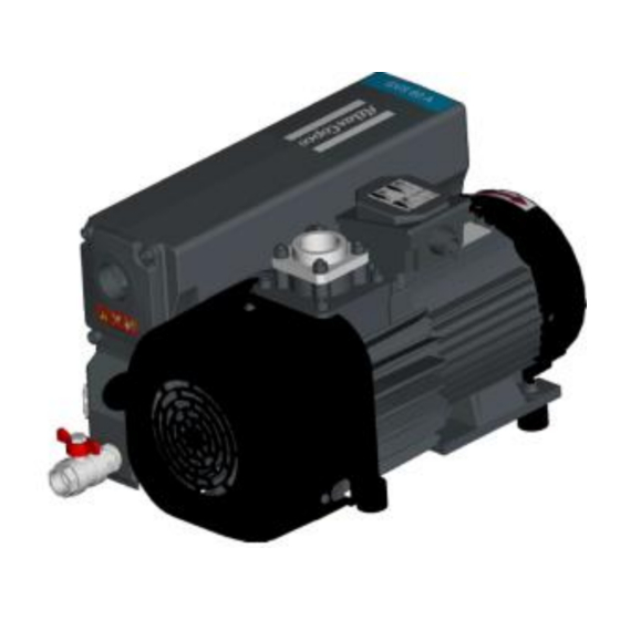
Summary of Contents for Atlas Copco GVS 16A
- Page 1 Atlas Copco Oil-sealed rotary vane vacuum pumps GVS 16A, GVS 25A, GVS 40A, GVS 60A, GVS 100A, GVS 200A, GVS 300A, GVS 470A, GVS 630A Instruction Book 6996 0224 30 Issue B...
- Page 3 Atlas Copco Oil-sealed rotary vane vacuum pumps GVS 16A, GVS 25A, GVS 40A, GVS 60A, GVS 100A, GVS 200A, GVS 300A, GVS 470A, GVS 630A Instruction book Original instructions Copyright notice Any unauthorized use or copying of the contents or any part thereof is prohibited. This applies in particular to trademarks, model denominations, part numbers and drawings.
- Page 4 Instruction book 6996 0224 30...
-
Page 5: Table Of Contents
Instruction book Table of contents Safety precautions ............................7 Safety icons ..............................7 General precautions ............................7 Safety precautions during installation ......................7 Safety precautions during operation ......................9 Safety precautions during maintenance or repair ..................10 General description........................... 12 What is vacuum and how is flow rate understood .................. -
Page 6: Table Of Contents
Instruction book V-belt tensioning ............................57 Problem solving ............................58 Technical data ............................59 Reference conditions and limitations ......................59 Pump data ..............................62 Motor data ..............................67 Declaration of conformity ......................... 69 6996 0224 30... -
Page 7: Safety Precautions
Instruction book Safety precautions Safety icons Explanation Danger for life Warning Important note General precautions 1. The operator must employ safe working practices and observe all related work safety requirements and regulations. 2. If any of the following statements does not comply with the applicable legislation, the stricter of the two shall apply. - Page 8 19. Whenever air containing hazardous substances is sucked in (i.e. biological or microbiological agents), use abatement systems placed upstream of the vacuum pump. 20. Any vacuum pump placed in an application with inlet gas stream temperatures above the published maximum temperature should be approved by Atlas Copco prior to start-up. 6996 0224 30...
-
Page 9: Safety Precautions During Operation
Instruction book Also consult sections Safety precautions during operation Safety precautions during maintenance or repair. These precautions apply to machinery processing or consuming air or inert gas. Processing of any other gas requires additional safety precautions typical to the application which are not included herein. Some precautions are general and cover several machine types and equipment;... -
Page 10: Safety Precautions During Maintenance Or Repair
Instruction book 11. Do not remove any of, or tamper with, the sound-damping material. 12. Never remove or tamper with the safety devices, guards or insulations fitted on the machine. 13. The oil separator tank can be slightly pressurised. Do not open and do not leave oil filler or drain plugs open during operation. - Page 11 Instruction book temperatures and time settings are correct. Check that all control and shut-down devices are fitted and that they function correctly. If removed, check that the coupling guard of the vacuum pump drive shaft has been reinstalled. 16. Every time the separator element is renewed, examine the discharge and the inside of the oil separator vessel for carbon deposits;...
-
Page 12: General Description
Instruction book General description What is vacuum and how is flow rate understood What is vacuum and how to denote A vacuum is any pressure in a system that is below the ambient atmospheric pressure. It can be denoted in absolute terms or in effective (gauge) terms: ... - Page 13 There are 2 common but different ways to denote flow rate in vacuum. The first one is based on the displacement or volumetric flow rate and the second one is based on the throughput or mass flow rate. Atlas Copco vacuum pumps use volumetric flow rate to denote performance, the unit being actual m³/h. Displacement/volumetric flow rate...
- Page 14 Instruction book General description The GVS 16A up to GVS 630A are single-stage, oil-sealed and air-cooled rotary vane vacuum pumps driven by an electric motor. GVS 100A up to GVS 300A are also available without electric motor. GVS 470A and GVS 630A are belt driven.
-
Page 15: Air Flow
Instruction book Air flow Air drawn through the air intake filter (optional), the inlet protection screen and the inlet non-return valve is displaced by the vacuum pump element towards the air end exhaust valve. This valve ejects a mixture of air and oil into the exhaust filter element. After passing the exhaust filter element, clean air - conditioned to a few parts per million - is discharged through the outlet. - Page 16 Instruction book Flow diagram Flow diagram, GVS 16A and GVS 25A 6996 0224 30...
- Page 17 Instruction book Flow diagram, GVS 40A and GVS 60A 6996 0224 30...
- Page 18 Instruction book Flow diagram, GVS 100A and GVS 300A 6996 0224 30...
- Page 19 Instruction book Flow diagram, GVS 200A 6996 0224 30...
- Page 20 Instruction book Flow diagram, GVS 470A and GVS 630A 6996 0224 30...
-
Page 21: Oil Flow
Instruction book Oil flow Oil injected into the pump chamber serves to seal, lubricate and cool the pump. The oil entrained with the compressed gas is coarsely trapped in the bottom part of the oil casing. Then fine filtering occurs in the integrated exhaust filter elements. -
Page 22: Installation
Instruction book Installation Dimension drawings Dimension drawing GVS 16A and GVS 25A 6996 0224 30... - Page 23 Instruction book Dimension drawing GVS 40A 6996 0224 30...
- Page 24 Instruction book Dimension drawing GVS 60A 6996 0224 30...
- Page 25 Instruction book Dimension drawing GVS 100A 6996 0224 30...
- Page 26 Instruction book Dimension drawing GVS 200A 6996 0224 30...
- Page 27 Instruction book Dimension drawing GVS 300A 6996 0224 30...
- Page 28 Instruction book Dimension drawing GVS 470A 6996 0224 30...
- Page 29 Instruction book Dimension drawing GVS 630A 6996 0224 30...
-
Page 30: Installation Proposal
Instruction book Installation proposal Installation proposal GVS 16A and 25A 6996 0224 30... - Page 31 Instruction book Installation proposal GVS 40A 6996 0224 30...
- Page 32 Instruction book Installation proposal GVS 60A 6996 0224 30...
- Page 33 Instruction book Installation proposal GVS 100A 6996 0224 30...
- Page 34 Instruction book Installation proposal GVS 200A 6996 0224 30...
- Page 35 Instruction book Installation proposal GVS 300A 6996 0224 30...
- Page 36 Instruction book Installation proposal GVS 470A 6996 0224 30...
- Page 37 Instruction book Installation proposal GVS 630A Note 1 Dimensions I and F depend on the motor selected. 6996 0224 30...
- Page 38 The following list must be used as a guide for the installation of GVS vacuum pumps. The list is not exhaustive. Every vacuum pump installation is unique and care must be exercised in the placement of each pump. If you are unsure of any installation variable, please consult Atlas Copco. ...
- Page 39 Accessories retrofitted on oxygen pumps must be hydrocarbon degreased using an adapted solvent. Take all required precautions. Use of PFPE fluid provided by Atlas Copco only. Making sure that PFPE fluid level in the pump is correct before switching on.
-
Page 40: Motor Installation (If Applicable)
Instruction book Motor installation (if applicable) It is possible to install any type of electric or hydraulic motor of which the specifications comply to the technical data, with flange and shaft corresponding to: M112 – B14 (FT130) size as per standard IEC60072-1 (for Europe and Wide motor versions) and motor frame size 213 with 184 TCH flange for Nema motor version for GVS 100A ... - Page 41 Instruction book GVS 300A Motor coupling half position Motor installation instructions for GVS200A 1. Place a suitable container underneath the pump to catch the oil spillage. Remove the drain plug. Drain the pump. 2. Remove the pump coupling housing, disconnect the finned oil cooler and unscrew the two connectors (1 on oil casing and 1 on tube) as explained in following steps: 6996 0224 30...
- Page 42 Instruction book a. Remove three screws securing coupling housing. Remove coupling housing. b. Unscrew the oil cooler connector on casing. c. Unscrew the oil cooler connector on tube. 6996 0224 30...
- Page 43 Instruction book 3. Place motor in vertical orientation so that motor shaft facing upwards. 4. Ensure the turbine support on a 3mm thickness spacer. 5. Tighten the screw to 2 N.M torque. Apply LOCTITE 243. 6996 0224 30...
-
Page 44: Electrical Connections
Instruction book 6. In order to assemble motor and coupling housing on pump, follow step 2 in reverse order. 7. Cover the pump. Mount lifting bar on the pump. 8. Refit the drain plug. Pour recommended quantity of oil in the pump. Electrical connections ... -
Page 45: Pictographs
Instruction book Pictographs Reference Designation Rotation direction of fan Warning: voltage Hot surface warning 6996 0224 30... -
Page 46: Operating Instructions
The pump is supplied with oil inside (except for O - versions). If the air intake filter (optional) is delivered loose, mount it in a leak-tight manner according to the following instructions: GVS 16A and GVS 25A GVS 40A up to GVS 300A 6996 0224 30... - Page 47 Instruction book The air intake filter (optional) should be installed in a horizontal position to prevent filtered dust falling into the pump inlet when replacing the air intake filter element and resulting damage to the pump. Initial start-up instructions: Check the process lines for the correct size to prevent high pressure drop and for cleanliness to protect the vacuum pump.
-
Page 48: Starting
Instruction book Starting Procedure: Check oil level and oil condition. Switch on the voltage. To avoid excessive energy consumption and damage to the vacuum pump the maximum allowed starting frequency is 6 starts per hour. For more frequent operation, let the pump run continuously and control the vacuum demand by a pitot valve on the pump inlet. -
Page 49: Maintenance
For overhauling or carrying out preventive maintenance, service kits are available (see section Service kits Service contracts Atlas Copco offers several types of service contracts, relieving you of all preventive maintenance work. Consult your Atlas Copco Customer Centre. General When servicing, replace all removed O-rings and washers. -
Page 50: Oil Specifications
Store the pump in its packing in a covered, dry place at a temperature between -20°C (-4 °F) and 50°C (122 °F). If the vacuum pump is going to be stored without running from time to time, protective measures must be taken. Consult Atlas Copco. 6996 0224 30... -
Page 51: Service Kits
Service kits For overhauling and for preventive maintenance, a wide range of service kits is available. Service kits comprise all parts required for servicing the component and offer the benefits of genuine Atlas Copco parts while keeping the maintenance budget low. -
Page 52: Adjustments And Servicing Procedures
Lift the 3 exhaust filters from the W shaped metal sheet holder and remove them from the oil casing. Make sure that the new exhaust filters have the O-ring (opposite side of overpressure valve) and grease them using Atlas Copco vacuum grease. 6996 0224 30... - Page 53 Instruction book Replace the O-ring of the exhaust plate. Insert new exhaust filters. They are guided in the oil casing correct position. Make sure the compression springs are behind the W shaped metal sheet holder. Plug the exhaust plate on the W shaped metal sheet holder with the 2 location pins and screw the exhaust plate on the oil casing using a 8 mm Allen key.
-
Page 54: Oil And Oil Filter Change
Let the pump run with closed intake for a few minutes, stop the pump and check the oil level. Top up if necessary. Oil filter change (not applicable to GVS 16A and GVS 25A) Drain the used oil completely following above instructions. -
Page 55: Cleaning Radiator, Motor Fan Guard And Pump
Instruction book Cleaning radiator, motor fan guard and pump Radiator, motor fan guard and pump must be kept clean. This can be done using compressed air and a dry cloth. Be careful not to damage the oil cooler (if applicable) by cleaning with compressed air or by exerting excessive pressure with the cloth. - Page 56 Instruction book GVS 630A Tools required: Key 19 and 24. Take off the hood. Loosen the applicable nuts. Loosen the push rod. Remove the V belts. Reassemble in reverse sequence. Stretch the V-Belts with the V-belt tension meter. section 6.7 for V-belt tensioning.
-
Page 57: V-Belt Tensioning
Instruction book V-belt tensioning How to use the v-belt tension meter The tension meter is a tool designed to check and re-tighten the v-belts. It is made of two sliding pipes with a graded spring inside. Set the first o-ring at 10 mm (PIX) on the millimeter scale or 25 Inches of Span, as shown figure 8, picture 3, and the other o-ring on position 0 on the Newton scale. -
Page 58: Problem Solving
Instruction book Problem solving Problem Cause Remedy The pump does not run (A) No voltage Provide power supply Thermal switch has tripped Identify cause and reset switch Room temperature too low Restore temperature to allowed value Motor damaged Contact Service Department The pump cannot reach stated Low oil level To up oil vacuum (B) -
Page 59: Technical Data
Instruction book Technical data Reference conditions and limitations Reference conditions 100A 200A 300A 470A 630A Ambient barometric mbar(a) 1013 1013 1013 1013 1013 1013 1013 1013 1013 pressure Ambient Torr barometric (mmHg) pressure Relative air humidity Air inlet °C temperature Air inlet °F temperature... - Page 60 Instruction book Limitations 100A 200A 300A 470A 630A Maximum inlet pressure for mbar 1013 1013 1013 1013 1013 1013 1013 1013 1013 continuous operation Maximum inlet torr pressure for continuous operation Maximum ambient °C temperature Maximum ambient °F temperature Minimum ambient temperature (see °C note)
- Page 61 Instruction book 100A 200A 300A 470A 630A Maximum inlet pressure for mbar water vapour with big gas ballast (or 2 GB) Maximum inlet pressure for torr water vapour with 37.5 52.5 big gas ballast (or 2 GB) Maximum water vapour pumping rate vapour with kg/h 0.05...
-
Page 62: Pump Data
Instruction book Pump data All data are mentioned at reference conditions. Description Unit 100A 200A 300A 470A 630A Volumetric flow m³/h 97.5 rate 50 Hz Volumetric flow 14.5 25.9 34.8 57.4 rate 50 Hz Volumetric flow m³/h 18.7 rate 60 Hz Volumetric flow 17.1 31.2... - Page 63 Instruction book Description Unit 100A 200A 300A 470A 630A Mean sound pressure level at 1 dB(A) m distance 50 Hz Mean sound pressure level at 1 dB(A) m distance 60 Hz Rotor speed 50 1500 1500 1500 1500 1500 1500 1500 Rotor speed 60 1800...
- Page 64 Instruction book 50 Hz 60 Hz GVS 16A GVS 16A GVS 25A GVS 25A GVS 40A GVS 40A = Without gas ballast = With gas ballast 6996 0224 30...
- Page 65 Instruction book 50 Hz 60 Hz GVS 60A GVS 60A GVS 100A GVS 100A GVS 200A GVS 200A = Without gas ballast = With gas ballast 6996 0224 30...
- Page 66 Instruction book 50 Hz 60 Hz GVS 300A GVS 300A GVS 470A GVS 470A GVS 630A GVS 630A = Without gas ballast = With gas ballast 6996 0224 30...
-
Page 67: Motor Data
Type Service factor 50 Hz 60 Hz 50 Hz 60 Hz 180-264 1 ph 180-264 1 ph Wide GVS 16A 200/240±10% (Δ) 200/240±10% (Δ) 5,0 (Δ) / 4,3 (Δ) / Wide 380/415±10% (Y) 380/460±10% (Y) 2,2 (Y) 2,2 (Y) 198-253 1 ph... - Page 68 Instruction book Motor voltage supply range (V) Nominal current (A) Model Type Service factor 50 Hz 60 Hz 50 Hz 60 Hz 200±10% (YY) 200±10% (YY) 220/230/240±10% 24,6 (YY) 26 (YY) 220/230±10% (Δ) (Δ) 21,4 (Δ) 23,6 (Δ) Europe 380/400/460±10% 380/400/415±10% 12,3 (Y) 13,5 (Y)
-
Page 69: Declaration Of Conformity
Machine name VACUUM PUMP Machine type GVS 16A, GVS 25A, GVS 40A, GVS 60A, GVS 100A, GVS 200A, GVS 300A, GVS 470A, GVS 630A Serial number This declaration covers all product serial numbers from the date this Declaration was signed onwards. - Page 70 подразбиране с директивите 10.а Издадено от 11 Инженеринг 12 Име 13 Подпис 14 Дата 15 място 1. PROHLÁŠENÍ O SHODĚ EU 2. My, společnost Atlas Copco Airpower n.v., prohlašujeme na naší výhradní odpovědnost , že tento produkt 3. Název stroje 4. Typ stroje 5. Výrobní číslo 6. který spadá pod ustanovení článku 12.2 Směrnice Evropského společenství...
- Page 71 Equipo de baja tensión - 2014/35/UE d. RoHS - 2011/65/UE 2015/863/UE 8.a. Las normas técnicas y armonizadas utilizadas se identifican en los anexos que siguen 8.b. Atlas Copco Airpower NV. está autorizado para elaborar el expediente técnico 9. Conformidad del producto con la especificación y por implicación con las directivas 10. Elaborado por 11. Ingeniería del producto 12.
- Page 72 2014/35/UE d. RoHS - 2011/65/UE 2015/863/UE 8.a. Gli standard armonizzati e tecnici utilizzati sono identificati negli allegati che seguono 8.b.Atlas Copco Airpower NV. è autorizzato a costituire il fascicolo tecnico. 9. Conformità del prodotto alla specifica ed implicitamente alle direttive 10. Compilato da 11. Progettazione del prodotto 12. Nome 13. Firma 14. Data 15.
- Page 73 - 2014/30/EF c. Lavspenningsutstyr - 2014/35/EF d. RoHS - 2011/65/EF 2015/863/EF 8.a. De harmoniserte og de tekniske standardene som er brukt, er angitt i vedleggene som følger. 8.b. Atlas Copco Airpower NV. er autorisert til å kompilere den tekniske arkiv 9. Produktets samsvar med spesifikasjonen og følgelig med direktivene 10. Utsteder 11.
- Page 74 11. Návrh produktu 12. Názov 13. Podpis 14. Dátum 15. Miesto 1. IZJAVA EU O SKLADNOSTI 2. Mi, Atlas Copco Airpower n.v., s polno odgovornostjo izjavljamo, da je izdelek, 3. Ime stroja 4. Tip stroja 5. Serijska številka 6. ki spada pod določbe člena 12.2 Direktive 2006/42/ES o približevanju zakonodaj držav članic v zvezi s stroji, v skladu z ustreznimi bistvenimi zdravstvenimi in varnostnimi zahtevami te direktive.
- Page 76 We make performance stand the test of time. This is what we call - Sustainable Productivity Atlas Copco AB (publ) SE-105 23 Stockholm, Sweden Phone: +46 8 743 80 00 Reg. no: 556014-2720 www.atlascopco.com...
Need help?
Do you have a question about the GVS 16A and is the answer not in the manual?
Questions and answers