Atlas Copco PAC Series Instruction Manual
Hide thumbs
Also See for PAC Series:
- Instruction manual (68 pages) ,
- Instruction book (48 pages) ,
- Instruction manual (71 pages)

Related Manuals for Atlas Copco PAC Series


Summary of Contents for Atlas Copco PAC Series
- Page 1 Instruction Manual Instruction manual for PAC Series Pump English PAC H108 FSC01 ITH Scania DC0907A...
- Page 3 PAC H108 FSC01 ITH Instruction Manual for PAC Series Pump Instruction manual .................. 5 Circuit diagrams ..................62 Original instructions Printed matter No ATLAS COPCO - PORTABLE ENERGY DIVISION 2960 6880 00 www.atlascopco.com 02/2021...
- Page 4 While every effort has been made to ensure that the information in in this manual is correct, Atlas Copco does not assume responsibility for possible errors. Copyright 2021, Varisco S.r.L, PADOVA, ITALY. Any unauthorized use or copying of the contents or any part thereof is prohibited.This applies in particular to trademarks, model denominations, part numbers and drawings.
-
Page 5: Table Of Contents
Please read the following instructions carefully before starting to use your machine. While every effort has been made to ensure that the information in this manual is correct, Atlas Copco does not assume responsibility for possible errors. Atlas Copco reserves the right to make changes without prior notice. - Page 6 Engine consumable specifications .47 Technical specifications ..66 5.4.1 Engine fuel specifications......47 11.1 Technical specifications of unit/ 5.4.2 Engine oil specifications......47 engine/pump ........66 5.4.3 Engine coolant specifications....48 11.2 Dimension Drawing ......68 11.3 Torque values ........69 Checks and trouble shooting. .50 11.3.2 Critical torque values......
-
Page 7: Safety Precautions For Pumps
The policy of Atlas Copco is to provide the users of their Atlas Copco equipment. It is the responsibility of unsafe operating conditions. Take necessary steps to equipment with safe, reliable and efficient products. -
Page 8: General Safety Precautions
The manufacturer does not accept any liability for any covers shall be opened before sufficient cooling 15 When working on the unit, wear safety clothing. damage arising from the use of non-original parts and for time has elapsed; this to avoid the risk of Depending on the kind of activities these are: spontaneous ignition of oil vapour when air is safety glasses, ear protection, safety helmet... -
Page 9: Safety During Transport And Installation
- check the towbar, the brake system and the via the holes in the frame at the front and back or consult Atlas Copco. towing eye. Also check the coupling of the via the lifting beam. To prevent damage, never 15. -
Page 10: Safety During Use And Operation
5. Never refill fuel while the unit is running, unless down equipment, do so with caution and use the noise hazardous area and an obvious warning otherwise stated in the Atlas Copco Instruction appropriate protection, at least safety glasses, for shall be placed permanently at each entrance Book (AIB). -
Page 11: Safety During Maintenance And Repair
15. Safety shoes should be compulsory in any sure that all electric connections are securely inadvertent starting. In addition, a warning sign workshop and if there is a risk, however small, tightened. bearing a legend such as "work in progress; do of falling objects, wearing of a safety helmet not start"... -
Page 12: Tool Applications Safety
20. Make sure that oil, solvents and other substances -never smoke near batteries being, or having recently recommended or approved by Atlas Copco or likely to pollute the environment are properly been, charged, the machine manufacturer. Ascertain that the disposed of. -
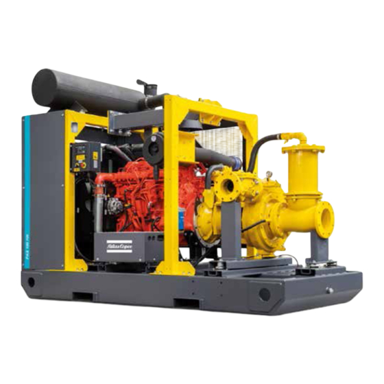
Page 13: Main Parts
Main parts General description The PAC H108 dry-prime centrifugal pumps, are suitable for handling clean water or liquids up to 50°C. The PAC H108 pumps are driven by a fluid-cooled diesel engine, manufactured by Scania. An overview of the main parts is given in the diagram below. Lifting beam Data plate Hole for forklift... - Page 14 Engine exhaust Air filter Coupling Centrifugal pump Check valve assembly Engine Filler cap engine oil Filler cap fuel Hinge assembly Muffler Oil filter Suction pipe Vacuum pump - 14 -...
-
Page 15: Flow Diagram
Flow Diagram - 15 -... -
Page 16: Markings
Markings Read the instruction manual Markings provide instructions and information. They before using the lifting eye. also warn of hazards. For convenience and safety, keep all markings in legible condition, replacing them when damaged or missing. Replacement markings are available from the factory. Read the instruction manual A brief description of all markings provided on the before servicing. -
Page 17: Field Of Application
Despite the pump is able to deal with air in the suction pump is incorporated. line, Atlas Copco recommends to avoid this situation 2.4.4 Safety devices Vacuum created in the suction pipe by the vacuum as far as possible in order to guarantee a better pump, forces water to penetrate the pump. -
Page 18: Control Panel
2.4.5 Control panel 2.4.7 Drain plugs and filler caps Electrical features The control panel grouping the controller, hour meter, The drain holes for the engine oil, the coolant and the The electrical features described in this chapter are fuel level gauge, ON/OFF switch etc., is placed at the plug for the fuel, are located and labelled on the standard provided on this pump. -
Page 19: Control Panel - Pw 500
Control panel - PW 500 The PAC H108 range of pumps are fitted with PW 500 controller. This is located inside the canopy and communicates via a display section in the front. It carries out the entire necessary task to control and protect the Pump. Operation Mode Selection key Controller Manual Operation... -
Page 20: General Description Of Pw 500
General description of PW 500 START BUTTON Pressing this button in Manual Mode will start the Pump. STOP BUTTON Pressing this button in manual mode will stop the pump in a controlled way. RESET BUTTON Press Reset Button to reset the controller. ARROW BUTTON Press Briefly to Show the instruments. - Page 21 Led Functions Starter Enable Key The Starter enable key is used to power the controller for starting the machine. Cumulative alarm with Engine stop Once the machine is running the starter key can be flipped Start Float Call Closed. to OFF position. It will not stop the machine. It will not Operation Mode Light - Controller in Manual Mode allow the engine to be re-cranked unless a manual input Operation Mode Light - Controller in Automatic Mode...
-
Page 22: Float Switches
2.7.1 Float switches Operating procedure: • The tank drains: The pump is fitted with two float switches for 1. Connect the float switches as follows: operation in Auto mode. These float switches must be • Connect the Start float to Connector indicated coupled to the connectors, located at the side of the by label “A Start float”. -
Page 23: Installation And Connection
Installation and connection To be able to lift the unit by means of a forklift, Lifting Installation rectangular slots are provided at the bottom of the Before lifting the unit, check its dimensions and frame. 3.2.1 Indoor installation weight, which can be found on the Data plate. If the pump is operated indoors, install an exhaust When lifting the unit, the hoist has to be placed in pipe of sufficient diameter to duct the engine exhaust... - Page 24 – Check that the inner earthing system is in compliance with the local legislation. – Use coolant for the engine cooling system. Refer to the Engine instruction book for the proper coolant mixture. – Check the tightness of the bolts and nuts. PAC H108 - 24 -...
-
Page 25: Suction And Discharge Pipework
In the same casing. way, bends in the suction should be avoided as much as possible. Atlas Copco recommends fluid velocities up to 2 m/s (6 ft/sec) on the suction and 3 m/s (9ft/sec) on the discharge. -
Page 26: Operating Instructions
Manual mode allows the operator to start and stop the programmable. unit manually. In this mode, float switches are not used. Atlas Copco recommends using the machine in 9. If the whole series of attempts is unable to start the automatic mode in order to prevent dry running. -
Page 27: Manual Operation Mode
Manual operation mode Settings PW 500 Starting 4.3.1 Acknowledge an alarm and faults When the engine protection device intervenes or when there are fault detections, 1. Switch on the battery switch. the controller displays the fault codes or messages (based on settings) with flashing of ALARM LED. - Page 28 Anomaly Messages Number of start up attempts (staring failure) Shut down In the event of no communication with the injection control unit of the engine, the Start in case of low battery charge anomaly fault activates. Over speed Shut down Note: - All the messages or instruments displayed on the display regarding the injection control unit and the CAN bus are identified by the character at the bottom Interrupted fuel float...
- Page 29 Can Bus Instruments: Cumulative Alarms The following parameters read by the injection control unit are displayed on the • POS 10 LED (RED Steady light): Anomaly managed by the injection unit screen when the engine is running. The injection control unit manages all will cause the engine to Stop anomalies regarding these instruments.
-
Page 30: General Feature Settings
4.3.2 General feature settings Weekly Automatic Test To use Option D) and E) make sure – With this option, the engine performs a test cycle 1. Press PROG (program) button that the Calendar Clock updated and when operating in Automatic Mode. OPERATION MODE BUTTON panel. -
Page 31: Maintenance
Maintenance The maintenance schedule contains a summary of the maintenance instructions. Read the respective section before taking maintenance measures. For engine maintenance refer to Engine Operation Manual. The maintenance schedule has to be seen as a guideline for units operating in a dusty environment typical to the pump's applications. - Page 32 Every Every Every Every Regular service period Daily Annually 500 hrs 1000 hrs 3000 hrs 2 years Fuel filter Replace Check level (if necessary top up) Coolant Check additive concetration Replace Engine tightness (visual inspection for Check leaks) Exhaust system including exhaust after Check treatment components for leaks Check...
- Page 33 Every Every Every Every Regular service period Daily Annually 500 hrs 1000 hrs 3000 hrs 2 years General Control panel Check for alarms and warnings Condensate and water from spillage-free Drain frame or catch basin (if applicable) Locks and hinges Grease Emergency stop Check function...
- Page 34 Every Every Every Every Regular service period Daily Annually 500 hrs 1000 hrs 3000 hrs 2 years Pump Check oil level (if necessary top up) Vacuum pump oil Replace Inspect (if necessary replace) Vacuum pump diaphragm and valves Replace Inspect (if necessary tension or replace) Vacuum pump belt Replace...
- Page 35 Every Every Every Every Regular service period Daily Annually 500 hrs 1000 hrs 3000 hrs 2 years Check valve Inspect (if necessary replace) Inspect function of floater and valve Separator Clean components Rubber couplings Inspect (if necessary replace) Pump shaft bearings Replace - 35 -...
-
Page 36: Pump Maintenance Procedures
Pump maintenance Residual liquid may be found in the procedures pump casing, head and suction line. Take the necessary precautions if liquid hazardous GENERAL RECOMMENDATIONS (inflammable, corrosive, poisonous, – Handling must be carried out by specialized infected). personnel to avoid damage to the pump and to persons. - Page 37 LUBRIFICATING THE PUMP LUBRIFICATING THE DIAPHRAGM VACUUM PUMP Every month check the oil level using indicators The vacuum pump is of diaphragm type; its (min. oil level, maximum oil level) and if necessary lubrication is oil bath type. to up through the cap (Ref. n°3). Running the vacuum pump with an insufficient MECHANICAL SEAL CHECK amount of oil can damage it.
-
Page 38: Adjustments And Service Procedures
Adjustments and service procedures 5.2.1 Positioning the impeller with reference to the wear plate(s) In all models, the distance between the top of the impeller blades and the surface of the wear plate must be between 0.3 - 0.6 mm To achieve this, dimensions A and B must be as nearly as possible equal. -
Page 39: Servicing Of Impeller
To adjust the wear plate untighten the (1) nuts (x4) Pump Hinge and tighten the (2) bolts (4x). The Atlas Copco Pump is integrated with a Hinge Servicing of impeller mechanism to access the impeller in order to perform basic cleaning and examining the impeller and wear Wear Plate Adjustment plate conditions. - Page 40 The belts used are the detachable link type; to remove the belt release the link, turning the head of the pin by 90 degrees Fig.A. Insert the tool turning it (to reassemble the belt, overlap the last link by inserting it on the head of the pin and turn it by 90°), Fig.B.
-
Page 41: Inspection Check Valve - Valmatic
5.2.3 Inspection check valve - Valmatic The Check Valve requires no scheduled lubrication or maintenance. For service or inspection, the valve can be serviced without removal from the line. All work on the valve should be performed by a skilled mechanic with proper tools and a power hoist for larger valves. -
Page 42: Engine Maintenance Procedures Scania Dc0907A
Engine maintenance procedures Scania DC0907A 5.3.1 Engine oil level check 5.3.2 Engine oil and oil filter change – Install and tighten the drain plug on the oil drain flexible. Consult the Engine Operation Manual for the oil Refer to the Engine Operation Manual for more –... -
Page 43: Replacing Fuel Filter Element
5.3.4 Servicing air filter engine 5.3.4.2 Recommendation 5.3.4.1 Main parts The Atlas Copco air filters are specially designed application. The use of non-genuine air filters may lead to severe damage of engine and/or alternator. Never run the unit without air filter element. -
Page 44: Replacing The Filter Element
5.3.5 Replacing the filter element New elements must also be inspected for tears or punctures before installation. 1. Release the snap clips (1) and remove the dust trap cover (2). Clean the inside of the cover. 2. Remove the element (3). 3. -
Page 45: Cleaning Cooler
5.3.6 Cleaning cooler 5.3.7 Cleaning the fuel tank – Steam cleaning in combination with a cleansing agent may be applied. To avoid damaging the coolers, angle between jet and coolers should be approx. 90°. Protect the electrical and controlling equipment, air filters, etc. against penetration of moisture. -
Page 46: Battery Care
5.3.8 Battery care – Rock the battery a few times so that possible air If a battery does not need any make-up water at all bubbles can escape; wait 10 minutes and check the over considerable time operation, Before handling batteries, read the level in each cell once more;... -
Page 47: Engine Consumable Specifications
ISO 3448, as follows: Specifications PAROIL retention and more alkalinity to control acid formation. PAROIL from Atlas Copco is the ONLY oil tested Engine Type of lubricant and approved for use in all engines built into Atlas PAROIL prevents Soot build-up. -
Page 48: Engine Coolant Specifications
Remove the cap slowly and only low as -25°C (-13°F). when coolant ambient Atlas Copco's PARCOOL EG extended life coolant is temperature. A sudden release of the new range of organic coolants purpose designed Order pressure from a heated cooling to meet the needs of modern engines. - Page 49 Order Litre cu.ft number 0.175 1604 5308 00 1604 5307 01 barrel 55.2 7.35 1604 5306 00 To ensure protection against corrosion, cavitation and formation of deposits, the concentration of the additives in the coolant must be kept between certain limits, as stated by the manufacturer's guidelines.
-
Page 50: Checks And Trouble Shooting
Checks and trouble shooting Not enough power Engine troubleshooting – Restriction in a fuel pipe. When a failure occurs, always The table below gives an overview of the possible report what you experienced before, engine problems and their possible causes. –... - Page 51 The pressure of the lubricating oil is too low – Incorrect valve tip clearances. – Fault in cold start system. – Wrong grade of lubricating oil. – Engine overload. – Restriction in fuel tank vent. – Not enough lubricating oil in sump. –...
- Page 52 Crankcase pressure – Restriction in breather pipe. – Vacuum pipe leaks or fault in exhaust. Bad compression – Restriction in air filter/cleaner or induction system. – Incorrect valve tip clearances. The engine starts and stops – Dirty fuel filter element. –...
-
Page 53: Pump Troubleshooting
Pump troubleshooting The paragraph reports the most common problems that may occur during use of the pump and the possible remedies. In case operation defects founded in the starting phase or after a period of operating time, before intervene on the pump is necessary: –... -
Page 54: Overview Of Possible Operating Problems
6.2.1 Overview of possible operating problems Symptom Possible cause Corrective action Pump does not prime 1. Suction tubes or inlet filter clogged. The Remove the obstruction. vacuum gauge indicates a high value. 2. Suction tube collapse. Use reinforced suction tube. 3. - Page 55 Low or no flow 1. The pump does not prime, See causes given in Pump does not prime. 2. Head required by the system is greater Revise system design or select a different pump. than the rated head of the pump. 3.
- Page 56 Pump does not provide enough pressure 1. Viscosity of the liquid is higher than Contact the pump manufacturer once you have measured the viscosity expected. of the liquid. Viscosity for centrifugal pumps should not exceed 50 cSt. Check for other possible causes: see Low or no flow. 2.
-
Page 57: Storage Of The Pump
Storage of the pump Storage Preparing for operation after storage – Store the pump in a dry, frost-free room which is well ventilated. Before operating the pump again, remove the wrapping. – Run the engine regularly, e.g. once a week, until it is warmed up. -
Page 58: Disposal
This concept can only succeed with your non-recyclable materials. help. Support disposing Your Atlas Copco pump consists mostly of metallic professionally. assuring correct materials, that can be remelted in steel and melting disposal of the product you help prevent works and are therefore amost infinitely recyclable. -
Page 59: Options
Options External fuel tank View inside Position 1: Indicates that the connection (with/without fuel supply line to the engine quick couplings) is connected to the internal fuel tank. The option external fuel tank connection allows to bypass the internal fuel tank and to connect an Position 2: Indicates that the external fuel tank to the unit. - Page 60 Overview Filler cap (fuel tank) Engine External fuel supply coupling Fuel filter engine Primary coarse fuel filter / water separator Fuel tank 3-way valve - 60 -...
-
Page 61: Suction And Discharge Pipes
Suction and discharge pipes Bauer Perrot/Cardan DIN / ASME Discharge DIN / ASME Discharge Bauer Discharge Perrot/Cardan Suction DIN / ASME Suction Bauer Suction Perrot/Cardan - 61 -... -
Page 62: Circuit Diagrams
Circuit diagrams 10.1 PW 500 - 62 -... -
Page 63: 10.2 Pw 500 - Auxiliaries
10.2 PW 500 - Auxiliaries - 63 -... -
Page 64: 10.3 Pw 500 - Harness
10.3 PW 500 - Harness - 64 -... - Page 65 - 65 -...
-
Page 66: Technical Specifications
Technical specifications 11.1 Technical specifications of unit/engine/pump FEATURES Pump model Engine model PAC H108 Product number (8381063349 ) 200 / 8" Connection (mm/in) Weight (kg) 3635 Fuel tank capacity (l) 89 / 3.5" Solids handling (mm) Dimensions A B C (mm) 3260 x 1930 x 2520 Engine Brand... - Page 67 FEATURES PAC H108 Mechanical seal oil tank (l) Non return check valve Ball type Pass maximum (kw) Eff maximum (%) 1200 Q Eff maximum (m Starting voltage (V) - 67 -...
-
Page 68: 11.2 Dimension Drawing
11.2 Dimension Drawing PAC H108 - 68 -... -
Page 69: 11.3 Torque Values
11.3 Torque values 11.3.1 General torque values 11.3.2 Critical torque values The following tables list the recommended torques applied for general applications Assemblies at assembly of the compressor. Axles to frame: For hexagon screws and nuts with strength grade 8.8 Wheel nuts Bolts, axle/frame Thread size... -
Page 70: 11.4 Data Plate
11.4 Data plate QR CODE Every electrically driven pump is equipped with an identification plate which gives the following information: Type of unit Product Number Serial Number Weight (kg) Maximum capacity of the pump (m3/h) Maximum head (m) Maximum speed (rpm) Power (kW) Voltage (V) 10 Current (A) -
Page 71: Spare Parts
Spare parts 12.1 Ordering spare parts For spare parts see parts list. To avoid errors in delivery, please give the following information when ordering spare parts: – Pump type. – Pump serial number – Quantity required. – Part number. – Part description. - Page 72 www.atlascopco.com...
Need help?
Do you have a question about the PAC Series and is the answer not in the manual?
Questions and answers