Sign In
Upload
Download
Table of Contents
Contents
Add to my manuals
Delete from my manuals
Share
URL of this page:
HTML Link:
Bookmark this page
Add
Manual will be automatically added to "My Manuals"
Print this page
×
Bookmark added
×
Added to my manuals
Manuals
Brands
Atlas Copco Manuals
Water Pump
GVS 16A
Instruction manual
Atlas Copco GVS 16A Instruction Manual
Oil-sealed rotary vane vacuum pumps
Hide thumbs
Also See for GVS 16A
:
Instruction book
(77 pages)
1
2
Table Of Contents
3
4
5
6
7
8
9
10
11
12
13
14
15
16
17
18
19
20
21
22
23
24
25
26
27
28
29
30
31
32
33
34
35
36
37
38
39
40
41
42
43
44
45
46
47
48
49
50
51
52
53
54
55
56
57
58
59
60
61
62
63
64
65
66
67
68
69
70
71
72
73
74
75
76
77
78
79
80
81
82
83
84
page
of
84
Go
/
84
Contents
Table of Contents
Bookmarks
Table of Contents
Table of Contents
Safety and Compliance
Definition of Warnings and Cautions
Trained Personnel
Safety Symbols
Important Safety Information
General Precautions
Safety Precautions During Installation
Safety Precautions During Operation
Safety Precautions During Maintenance or Repair
Description
Vacuum and Flow Rate
Figure 1 Vacuum and Flow Rate
Overview
Air Flow
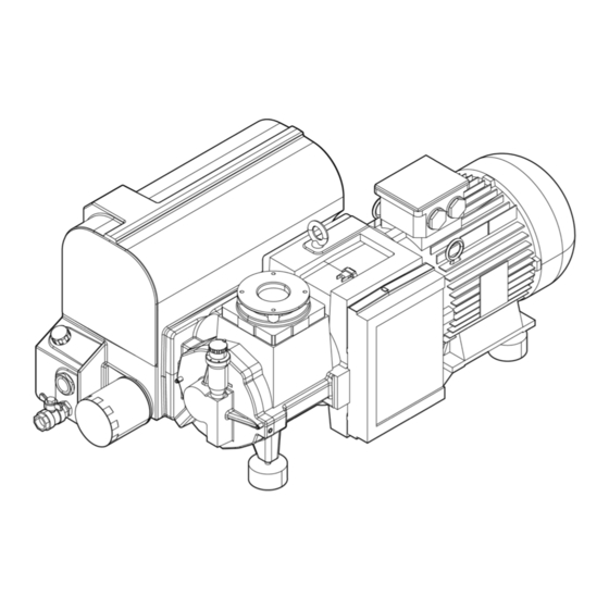
Figure 2 Pump Components
Figure 3 Air Flow Components - GVS 16A - 25A
Figure 4 Air Flow Components - GVS 40A - 300A
Figure 5 Flow Diagram - GVS 16A and GVS 25A
Figure 6 Flow Diagram - GVS 40A and GVS 60A
Figure 7 Flow Diagram - GVS 100A and GVS 300A
Figure 8 Flow Diagram - GVS 200A and GVS 220A
Oil Flow
Figure 9 Flow Diagram - GVS 470A and GVS 630A
Technical Data
Dimension Drawings
Figure 10 Dimension Drawing - GVS 16A and GVS 25A
Figure 11 Dimension Drawing - GVS 40A
Figure 12 Dimension Drawing - GVS 60A
Figure 13 Dimension Drawing GVS 60A
Figure 14 Dimension Drawing - GVS 200A
Figure 15 Dimension Drawing - GVS 220A
Figure 16 Dimension Drawing - GVS 300A
Figure 17 Dimension Drawing - GVS 470A
Figure 18 Dimension Drawing - GVS 630A
Performance Curves
Figure 19 Performance Curve - GVS 16A
Figure 20 Performance Curve - GVS 25A
Figure 21 Performance Curve - GVS 40A
Figure 22 Performance Curve - GVS 60A
Figure 23 Performance Curve - GVS 100A
Figure 24 Performance Curve - GVS 200A
Figure 25 Performance Curve - GVS 220A
Figure 26 Performance Curve - GVS 300A
Figure 27 Performance Curve - GVS 470A
Figure 28 Performance Curve - GVS 630A
Reference Conditions and Limitations
Pump Data
Motor Data
Installation
Installation Proposal
Figure 29 Installation Proposal - GVS 16A and GVS 25A
Figure 30 Installation Proposal - GVS 40A
Figure 31 Installation Proposal - GVS 60A
Figure 32 Installation Proposal - GVS 100A
Figure 33 Installation Proposal - GVS 200A
Figure 34 Installation Proposal - GVS 220A
Figure 35 Installation Proposal - GVS 300A
Figure 36 Installation Proposal - GVS 470A
Installation Guidelines
Figure 37 Installation Proposal - GVS 630A
Motor Installation (if Applicable)
Figure 38 Motor Coupling Half Position - GVS 100A
Figure 39 Motor Coupling Half Position - GVS 300A
Electrical Connections
Pictographs
Operation
Initial Start-Up Preparation
Start the Pump
During Operation
Stop the Pump
Taking out of Operation
Maintenance
Preventive Maintenance Schedule
Oil Specifications
Storage
Service Kits
Disposal of Used Material
Adjustments and Servicing
Drive Motor
Exhaust Filter Replacement
Oil and Oil Filter Change
Cleaning Radiator, Motor Fan Guard and Pump
Cleaning the Intake Filter (Optional) Element
Replacing V-Belts
V-Belt Tensioning
Figure 40 Belt Tensioning
Fault Finding
Service
Return the Equipment or Components for Service
Legal Declarations
Advertisement
Quick Links
1
Maintenance
2
Service Kits
Download this manual
Oil-Sealed Rotary Vane Vacuum Pumps
GVS 16A, GVS 25A, GVS 40A, GVS 60A,
GVS 100A, GVS 200A, GVS 220A,
GVS 300A, GVS 470A, GVS 630A
INSTRUCTION MANUAL
6996022430_C
Original instructions
Table of
Contents
Previous
Page
Next
Page
1
2
3
4
5
Advertisement
Table of Contents
Need help?
Do you have a question about the GVS 16A and is the answer not in the manual?
Ask a question
Questions and answers
Related Manuals for Atlas Copco GVS 16A
Water Pump Atlas Copco GVS 16A Instruction Book
Oil-sealed rotary vane vacuum pumps (77 pages)
Water Pump Atlas Copco GHS 350 VSD+ Instruction Book
Oil-sealed rotary screw vacuum pumps (124 pages)
Water Pump Atlas Copco GHS 350 VSD+ Instruction Manual
Oil-sealed rotary screw vacuum pumps (116 pages)
Water Pump Atlas Copco GHS VSD+ Series Instruction Manual
Oil-sealed rotary screw vacuum pumps (144 pages)
Water Pump Atlas Copco GLS 250 Instruction Book
Oil-sealed rotary piston pumps (50 pages)
Water Pump Atlas Copco GVD 175 Instruction Book
Oil-sealed dual stage rotary vane vacuum pumps (37 pages)
Water Pump Atlas Copco GVS 220A Instruction Manual
Oil-sealed rotary vane vacuum pumps (84 pages)
Water Pump Atlas Copco GHS 3800 VSD+ Instruction Book
Oil-sealed rotary screw vacuum pumps (132 pages)
Water Pump Atlas Copco GVD 18 Instruction Book
Oil-sealed dual stage rotary vane vacuum pumps (45 pages)
Water Pump Atlas Copco GVD 28 Instruction Book
(43 pages)
Water Pump Atlas Copco WEDA 30 Instruction Manual
(28 pages)
Water Pump Atlas Copco DZS 065V Instruction Book
Dry claw vacuum & overpressure pumps (56 pages)
Water Pump Atlas Copco AWC160 Instruction Manual
Liquid ring vacuum pumps (32 pages)
Water Pump Atlas Copco VAR 6 250 Instruction Manual
Var dry-prime centrifugal diesel driven pumps (78 pages)
Water Pump Atlas Copco DWS VSD+ Instruction Manual
Dry screw vacuum pump (137 pages)
Water Pump Atlas Copco LRP 700 VSD+ Instruction Book
Intelligent liquid ring vacuum pumps (124 pages)
This manual is also suitable for:
Gvs 25a
Gvs 40a
Gvs 60a
Gvs 100a
Gvs 200a
Gvs 220a
...
Show all
Gvs 300a
Gvs 470a
Gvs 630a
Table of Contents
Print
Rename the bookmark
Delete bookmark?
Delete from my manuals?
Login
Sign In
OR
Sign in with Facebook
Sign in with Google
Upload manual
Upload from disk
Upload from URL


Need help?
Do you have a question about the GVS 16A and is the answer not in the manual?
Questions and answers