Table of Contents
Advertisement
Advertisement
Table of Contents

Related Manuals for Unicorn LS2-H5300-D


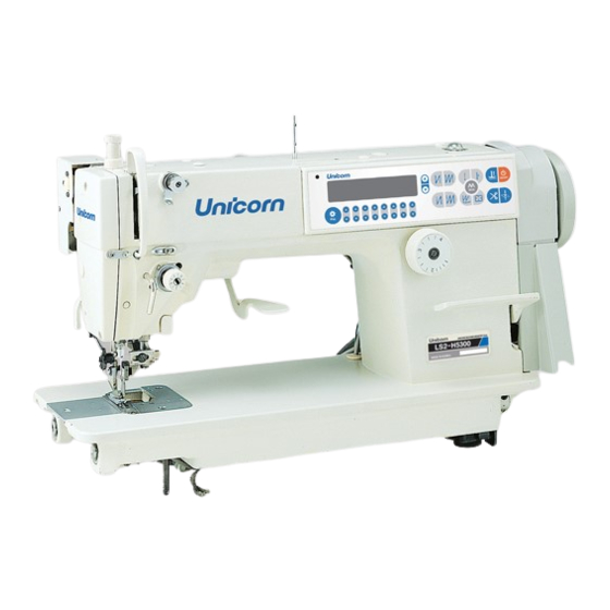
Summary of Contents for Unicorn LS2-H5300-D
- Page 2 17. The machine is only allowed to be used for the purpose intended. Other used are not allowed. 18. Remodel or modify the machine in accordance with the safety rules/standards while taking all the effective safety measures. UNICORN assumes no responsibility for damage caused by remodeling or modification of the machine.
- Page 3 FOR SAFE OPERATION 1. To avoid electrical shock hazards, neither open the cover of the electrical box for the motor nor touch the components mounted inside the electrical box. 1. To avoid personal injury, never operate the machine with any of the belt cover, Finger guard or safety devices removed.
-
Page 4: Table Of Contents
CONTENTS INSTRUCTION MANUAL 1. SPECIFICATIONS ..............................1 2. INSTALLATION ............................... 1 3. LUBRICATION ................................. 2 4. ADJUSTING THE AMOUNT OF OIL(OIL SPOTS) IN THE HOOK ..............3-4 5. ATTACHING THE NEEDLE............................ 5 6. SETTING THE BOBBIN INTO THE BOBBIN CASE....................5 7. -
Page 5: Specifications
1. SPECIFICATIONS Model H5600-D Application Light-weight materials and medium-heavy weight materials Sewing speed Max. 4,500 rpm Stitch length 4 mm Presser foot lift (by knee lifter) 4.5mm (standard) 13mm (max.) Needle DB x 1 #9~#18 2. INSTALLATION 1) The oil pan should rest on the four corners of the machine table groove. -
Page 6: Lubrication
3. LUBRICATION 1. Information on lubrication 1) Fill oil pan➊ with New Defrix Oil up to HIGH markⒶ. 2) When the oil level lowers below LOW markⒷ, refill the oil pan with the specified oil. 3) When operate machine after lubrication, you will see splashing oil through oil sight window➋... -
Page 7: Adjusting The Amount Of Oil(Oil Spots) In The Hook
4. ADJUSTING THE AMOUNT OF OIL (OIL SPOTS) IN THE HOOK WARNING Be extremely careful about the operation of the machine since the amount of oil has to be checked by turning the hook at a high speed. 1. Amount of oil (oil spots) confirmation paper 2. - Page 8 4. ADJUSTING THE AMOUNT OF OIL (OIL SPOTS) IN THE HOOK Sample showing the appropriate amount of oil 1) The amount of oil shown in the examples on Splashes of oil from the hook left should finely adjusted accordance with sewing processes. careful excessively increase...
-
Page 9: Attaching The Needle
5. ATTACHING THE NEEDLE WARNING Turn OFF the power before starting the work so as to prevent a accidents caused by abrupt start of the sewing machine. Follow the procedure described below to attach the needle, after confirming that the motor has come to a complete stop. -
Page 10: Threading The Machine Head
7. THREADING THE MACHINE HEAD WARNING Turn OFF the power before starting the work so as to prevent a accidents caused by abrupt start of the sewing machine. -
Page 11: Adjusting The Stitch Length
8. ADJUSTING THE STITCH LENGTH WARNING Turn OFF the power before starting the work so as to prevent a accidents caused by abrupt start of the sewing machine. 1) Turn stitch length dial➊ in the direction of the arrow, and align the desired number to marker dotⒶ... -
Page 12: Thread Take-Up Spring
10. THREAD TAKE-UP SPRING 1. Changing the stroke of thread take-up spring➊ 1) Loosen setscrew➋. 2) As you turn tension post➌ clockwise (in direction Ⓐ), the stroke of the thread take-up spring will be increased. 3) As you turn the knob counterclockwise (in direction Ⓑ), the stroke will be decreased. -
Page 13: Presser Foot Pressure
12. PRESSER FOOT PRESSURE WARNING Turn OFF the power before starting the work so as to prevent a accidents caused by abrupt start of the sewing machine. 1) Loosen nut➋, As you turn presser spring Ⓐ), the regulator clockwise (in direction presser foot pressure will be increased. -
Page 14: Height Of The Feed Dog
14. HEIGHT OF THE FEED DOG WARNING Turn OFF the power before starting the work so as to prevent a accidents caused by abrupt start of the sewing machine. 1) The feed dogⓐ is factory-adjusted so that it jut out from the throat plateⓑ surface 0.75mm to 0.85mm. -
Page 15: Adjusting The Height Of The Presser Foot
16. ADJUST THE HEIGHT OF THE PRESSER FOOT 17.ADJUST THE THREAD TAKE-UP STROKE 17. ADJUST THE THREAD TAKE-UP STROKE 18. OPERATION OF THE CLOTH CUTTING KNIFE... -
Page 16: Installing The Cloth Cutting Knife
19. ATTACHING THE CLOTH CUTTING KNIFE 20. CHANGING THE CUTTING WIDTH... -
Page 17: Adjusting The Knife Components
21. ADJUSTING THE KNIFE COMPONENTS 22. ADJUSTING THE HEIGHT OF THE KNEE LIFTER... -
Page 18: Other Replacement Parts
23. OTHER REPLACEMENT PARTS... -
Page 19: Winding The Lower Thread
24. WINDING THE LOWER THREAD 25. INSTALLING THE THREAD STAND... -
Page 20: Attaching The Waste Cloth Guide
26. ATTACHING THE WASTE CLOTH GUIDE... - Page 22 1. Machine Frame & Miscellaneous Cover Mechanism (1) - 1 -...
- Page 23 1. Machine Frame & Miscellaneous Cover Mechanism (1) Ref No. Part No. Description Q'ty 01-001 Plate 01-001-001 Plate Stick 01-002 Plate Gasket 01-003 Screw 01-004-01 Anti-oil Plate 01-004-02 Oil Wick 01-005 Rubber Plug 01-006 Rubber Plug 01-007 Thread Guide Rod 01-008-01 Screw 01-008-02...
- Page 24 1. Machine Frame & Miscellaneous Cover Mechanism (2) - 3 -...
- Page 25 1. Machine Frame & Miscellaneous Cover Mechanism (2) Ref No. Part No. Description Q'ty 01-042 Screw 01-043 Tension Releasing 01-044 Throat Plate 01-045 Spring Nut 01-046 Needle Plate Screw 01-047 Arm Thread Guide Left 01-048 Screw 01-049 Rubber Plug 01-050 Screw 01-051 Slide Plate Asm...
- Page 26 2. Main Shaft & Thread Take-up Lever Mechanism (1) - 5 -...
- Page 27 2. Main Shaft & Thread Take-up Lever Mechanism (1) Ref No. Part No. Description Q'ty 02-001 Screw 02-002 Thread Take-up Crank Shaft 02-003 Roller Felt 02-004 Thread Take-up Asm 02-005-01 Thread Take-up Lever Asm 02-005-02 Thread Take-up Lever 02-006 Thread Take-up Bearing 02-007 Crank 02-008...
- Page 28 2. Main Shaft & Thread Take-up Lever Mechanism (2) - 7 -...
- Page 29 2. Main Shaft & Thread Take-up Lever Mechanism (2) Ref No. Part No. Description Q'ty 02-044 Linker(1) 02-045 Rubber Ring 02-046 Screw 02-047 Friction Gear 02-048 Linker(2) 02-049 Screw(M6X0.75) 02-050 Crank Slide Block 02-051 Knife Driving Stud Connection Asm 02-052 Screw 02-053 Knife Cam Screw...
- Page 30 3. Needle Bar, Vertical Shaft & Hook Driving Shaft Mechanism - 9 -...
- Page 31 3. Needle Bar, Vertical Shaft & Hook Driving Shaft Mechanism Ref No. Part No. Description Q'ty 03-001 03-002 Needle Bar Bushing (Upper) 03-003 Needle Bar 03-004 Needle Rod Holder 03-005 Screw 03-006 Slide Block 03-007 Needle Bar Thread Guide 03-008 Needle Bar Bushing (Lower) 03-009 Screw...
- Page 32 4. Hand Lifter Mechanism - 11 -...
- Page 33 4. Hand Lifter Mechanism Ref No. Part No. Description Q'ty 04-001 Hand Lifter 04-002 Screw 04-003 Rubber Ring 04-004 Hand Lifter Cam Sam 04-005 Presser Bar Bushing 04-006 Screw 04-007 Link Shaft 04-008 E-Ring 04-009 Presser Foot Asm 04-010 Wire Holder Bracket (Lower) 04-011 Hinge Screw 04-012...
- Page 34 5. Feed Mechanism (1) - 13 -...
- Page 35 5. Feed Mechanism (1) Ref No. Part No. Description Q'ty 05-001 Feed Adjust Rod 05-002 Feed Regulator Pin 05-003 Screw 05-004 Feed Regulator 05-005 Feed Regulator Bushing 05-006 Screw 05-007 Feed Regulator Screw 05-008 Spring 05-009 Feed Adjust Pin 05-010 Feed Dial 05-011 Screw...
- Page 36 5. Feed Mechanism (2) - 15 -...
- Page 37 5. Feed Mechanism (2) Ref No. Part No. Description Q'ty 05-045 Lifting Crank (Back) 05-046 Screw 05-047 Hinge Screw 05-048 Feed Driving Shaft 05-049 Thrust Collar 05-050 Screw 05-051 Feed Rocker Shaft Bushing 05-052 Install Plate 05-053 Screw 05-054 Retaining Ring 05-055 Feed Bar Crank 05-056...
- Page 38 6. Thread Trimmer Mechanism - 17 -...
- Page 39 6. Thread Trimmer Mechanism Ref No. Part No. Description Q'ty 06-001 Thread Shear Cam 06-002 Housing Rubber 06-003 Screw 06-004 Secant Knife 06-005 Screw 06-006 Protect Needle Patch 06-007 Washer 06-008 Screw 06-009 Knife Bracket 06-010 Partiality Shank Asm 06-011 Washer 06-012 Screw...
- Page 40 7. Automatic Reverse Feed Mechanism - 19 -...
- Page 41 7. Automatic Reverse Feed Mechanism Ref No. Part No. Description Q'ty 07-001 LED Light&Back Stitch Asm 07-002 LED Light Cover 07-003 Washer 16X24X2.6 07-004 Press Button 07-005 Press Button Bracket 07-006 PCB Board 07-007 Rubber Plunger 07-008 E-Ring 07-009 Plunger Arm Pin 07-010 Reverse Feed Magnet Asm 07-011...
- Page 42 8. Oil Lubrication Mechanism & Bobbin Mechanism - 21 -...
- Page 43 8. Oil Lubrication Mechanism & Bobbin Mechanism Ref No. Part No. Description Q'ty 08-001 Oil Sight Window 08-002 Rubber Ring 08-003 Main Shaft Oil Tube 08-004 Screw 08-005 Oil Felt Presser 08-006 Oil Return Tube Asm 08-006-01 Return To Asphalt Felt 08-006-02 Oil Return Tube 08-007...
- Page 44 9. Oil Pan Mechanism - 23 -...
- Page 45 9. Oil Pan Mechanism Ref No. Part No. Description Q'ty 09-001 Oil Reservoir 09-003 Oil Reservoir Gasket 09-004-01 Quakeproof Mat, Small 09-004-02 Quakeproof Mat, Larger 09-005 Screw 09-006 Rubber Ring 09-007 Knee Lifting Rotating Arm 09-008 Spring 09-009 E-Ring 09-010 Vertical Shaft Fitting Arm 09-011 Screw...
- Page 46 10. Thread Stand Mechanism Ref No. Part No. Description Q'ty 10-001 Thread Stand Asm 10-002 Spool Retainer 10-003 Spool Pin 10-004 Spool Rest Cushion 10-005 Spool Rest 10-006 Screw 10-007 Thread Guide Arm Joint 10-008 Spool Rest Rod Rubber Cap 10-009 Spool Rest Arm 10-010...
- Page 47 11. Accessories Ref No. Part No. Description Q'ty 11-001 Machine Hinge Plate Asm 11-002 Nail 11-003 Machine Hinge Plate 11-004 Screw Driver, Large 11-005 Screw Driver, Medium 11-006 Screw Driver, Small 11-007 Bobbin 11-008 Head Cover 11-009 Rest 11-010 Oil Reservoir Asm 11-011 Needle 11-012...
- Page 48 12. Driver Mechanism Ref No. Part No. Description Q'ty 12-001 Motor Cover 12-002 Screw 12-003 Motor Ass 12-004 Screw 12-005 Spring Washer 12-006 Panel Setting Plate 12-007 Control Box 12-008 Shaft Plate 12-009 Washer - 27 -...
Need help?
Do you have a question about the LS2-H5300-D and is the answer not in the manual?
Questions and answers