
Subscribe to Our Youtube Channel
Related Manuals for Thermo Scientific BF51728


Summary of Contents for Thermo Scientific BF51728
- Page 1 Thermo Scientific Lindberg/Blue M Moldatherm 1100°C Box Furnace Models: BF51728, BF51748, BF51766, BF51794 BF51828, BF51848, BF51866, BF51894 Installation and Operational Manual 330985H01 Rev. A April, 2020...
- Page 2 © 2020 Thermo Fisher Scientific Inc. All rights reserved. Thermo Fisher Scientific Inc. provides this document to its customers with a product purchase to use in the product operation. This document is copyright protected and any reproduction of the whole or any part of this document is strictly prohibited, except with the written authorization of Thermo Fisher Scientific Inc.
-
Page 3: Table Of Contents
Table of Contents Table of Contents Chapter 1 Safety Notes ..............1-5 Explanation of Symbols . - Page 4 Table of Contents 1-Program 8-Segment Controller Operation ..........6-39 Soft Start Timer .
- Page 5 Figure 8 Door Insulation Replacement ...................... 9-59 Figure 9 Heating Unit Replacement ......................9-61 Figure 10 Wiring Diagram (BF51728, BF51828) ..................10-65 Figure 11 Wiring Diagram (BF51748, BF51766, BF51848 & BF51866) ........... 10-66 Figure 12 Wiring Diagram (BF51794, BF51894) ..................10-67 1100°C Box Furnace...
-
Page 6: Chapter 1 Safety Notes
Safety Notes Explanation of Symbols DANGER : Indicates a hazardous situation which, if not avoided, will result in death or serious injuries. WARNING : Indicates a hazardous situation which, if not avoided, could result in death or serious injuries. CAUTION : Indicates a situation which, if not avoided, could result in damage to equipment or property. -
Page 7: Safety Considerations
| Safety Notes Chapter 1 Safety Considerations DANGER : Do not modify or use equipment in a manner other than expressly intended. Modification of equipment other than that for which it is explicitly designed could cause severe injury or death. Any customer after-market retrofit violates the warranty of the equipment. -
Page 8: Standards And Directives
Safety Notes | Chapter 1 WARNING : When installing, maintaining, or removing the fiberglass insulation, the following precautions will minimize airborne dust and fiber: Keep personnel not involved in the installation out of the area. Use a good vacuum to clean area and equipment. Use a dust suppressant if ... - Page 9 | Safety Notes Chapter 1 NOTE: This equipment has been tested and found to comply with the limits for a Class A digital device, pursuant to part 15 of the FCC Rules. These limits are designed to provide reasonable protection against harmful interference when the equipment is operated in a commercial environment.
- Page 10 Safety Notes | Chapter 1 Our compliance is witnessed by written declaration from our suppliers and/or component testing. This confirms that any potential trace contamination levels of the substances listed above are below the maximum level set by the latest regulations or are exempt due to their application.
- Page 11 | Safety Notes Chapter 1 1-10 | 330985H01 1100°C Box Furnace...
-
Page 12: Chapter 2 Introduction
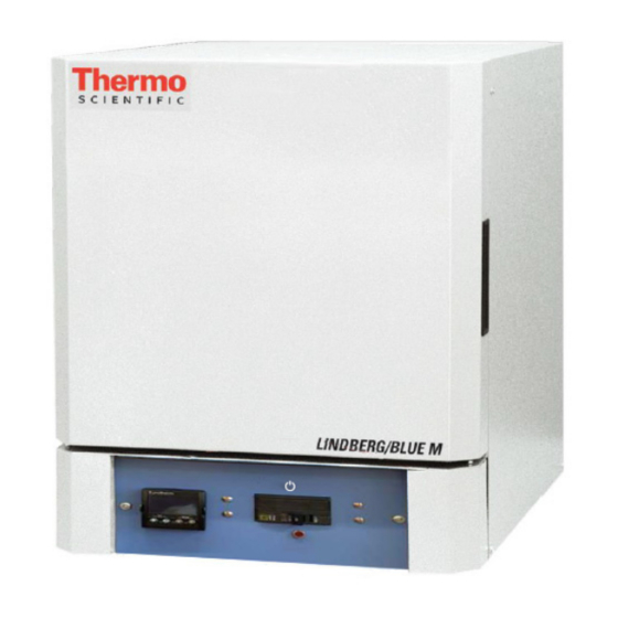
Introduction Figure 1 1100°C Box Furnace Thermo Fisher Scientific 1100°C box furnace series is a family of ultra lightweight, ® economical, laboratory box furnaces. The low thermal mass Moldatherm insulation/heating element provides fast duty cycles, energy conservation, and efficient programming. Refer to Table 1 “1100°C Moldatherm Box Furnace Series” for specifications. -
Page 13: Intended Use
| Introduction Chapter 2 Digital instrumentation for precise temperature setpoint and display. Microprocessor capable of automatically optimizes control parameters during furnace operation. Main power ON/OFF switch on control panel. Safety interlock switch automatically interrupts power to heating element when door ... -
Page 14: Specifications
Introduction | Chapter 2 Specifications Table 1 1100°C Moldatherm Box Furnace Series BF51748 A-1* BF51748C-1** BF51766 A-1* BF51766C-1** BF51728C-1 Model BF51794C-1** BF51748COMA-1 BF51748KC-1*** BF51766COMA-1 BF51766KC-1*** BF51728RHDC-1 Capacity 5.3 L 5.3 L 18.4 L 42.5 L (0.07 cu.ft.) (0.07 cu.ft.) (0.19 cu.ft.) (0.19 cu.ft.) (0.65 cu.ft.) (1.5 cu.ft.) - Page 15 | Introduction Chapter 2 2-14 1100°C Box Furnace 330985H01...
-
Page 16: Chapter 3 Pre-Installation
Pre-Installation Unpacking Carefully unpack and inspect the unit and all accessories for damage, if you find any damage, keep the packing materials and immediately report the damage to the carrier. We will assist you with your claim, if requested. Do not return goods to Thermo Fisher Scientific without written authorization. -
Page 17: Atmosphere Systems
| Pre-Installation Chapter 3 Atmosphere Systems The 1100°C box furnace series are not designed for use with combustible or inert atmospheres requiring an air tight chamber. If an exhaust port is used, the furnace should not be located in an enclosed area without proper ventilation. WARNING : Do not use combustible gases directly in this furnace. -
Page 18: Chapter 4 Installation
3" (7.62 cm) of space on all sides of the unit and 12" (30.48 cm) above the unit. Wiring For detailed wiring information, refer to: Figure 10 “Wiring Diagram (BF51728, BF51828)”, Figure 11 “Wiring Diagram (BF51748, BF51766, BF51848 & BF51866)” or ... - Page 19 208-240 VAC Mains Electrical (BF51728 and BF51828 Only) The BF51728 and BF51828 are 208-240 VAC furnaces and do not include a 240 VAC grounded plug and cord set. Furnace installation requires L1, L2, and ground wire (not provided). The required wire size is 10 AWG for 23.3 Amps @ 240 V.
-
Page 20: Mains Electrical/Thermocouple Check
Installation | Chapter 4 Mains Electrical/Thermocouple Check Before initial start up, inspect the furnace's wiring connections: 1. Remove the corner screws on the back panel of the furnace and detach the back panel. 2. Check that the thermocouple is securely mounted and undamaged. 3. -
Page 21: Exhaust Vent
| Installation Chapter 4 Exhaust Vent Flow from the exhaust vent on the top of the unit can be adjusted by inserting or removing the plug provided. For most applications, the exhaust vent should be fully plugged during operation of the furnace;... -
Page 22: Atmosphere Inlet
Installation | Chapter 4 Figure 4 Preventing Chimney Effect Atmosphere Inlet All Moldatherm box furnaces have a factory-installed air/atmosphere inlet. Most inert atmospheres (i.e. nitrogen, argon, and helium) can be safely run in this box furnace. However, maximum temperatures may be derated depending on atmosphere. An initial burn-in period in air is recommended. -
Page 23: Hearth Plate Information
| Installation Chapter 4 4. Align the mounting holes in the rear housing panel with the holes in the atmosphere inlet port and secure the assembly with the mounting screws. Figure 5 Atmosphere Inlet Port Hearth Plate Information CAUTION : Most hearth plate materials are made of ceramic fiber and can be broken if dropped. -
Page 24: Chapter 5 Start-Up
Start-Up WARNING : After transport and decommissioning, or storage under humid conditions a drying-out process must be performed due to hydroscopic nature of the ceramic fiber insulation. During the drying-out process the equipment cannot be assumed to meet all the safety requirements of the IEC 61010-2-010 standard. WARNING : Observe the following precautions when operating the furnace: Never stand in front of an open furnace. -
Page 25: Door Seal Check
| Start-Up Chapter 5 12. Highly recommended to Auto Tune unit for application prior to use refer to section “Auto Tuning” . Refer to section “Eurotherm 3216 Controller” for detailed start up steps. Door Seal Check It is very important to check the door seal before using this furnace. Door seal integrity is essential to maintain temperature uniformity and to prevent fumes being released into the area surrounding the furnace. - Page 26 Start-Up | Chapter 5 4. After each adjustment recheck the door seal. The door seal has been adjusted properly if there is no heat loss when operating the furnace up to 500°C. WARNING : When installing, maintaining, or removing the fiberglass insulation, the following precautions will minimize airborne dust and fiber: Keep personnel not involved in the installation out of the area.
- Page 27 | Start-Up Chapter 5 5-26 1100°C Box Furnace 330985H01...
-
Page 28: Chapter 6 Main Controller: 1X8 & 5X16 Segment Programmable
Main Controller: 1x8 & 5x16 Segment Programmable | Chapter 6 Main Controller: 1x8 & 5x16 Segment Programmable Eurotherm 3216 Controller The Eurotherm 3216c and 3216p temperature controllers sense the furnace's chamber air temperature (the PV or process value) and provides the heat needed to reach the required set point. -
Page 29: Operator Interface & Home Display
| Main Controller: 1x8 & 5x16 Segment Programmable Chapter 6 Operator Interface & HOME Display When the controller is turned ON, it will perform a brief self-test and then display the HOME Display page. The measured value (process value) is found in the upper display and the set point is found in the lower display. -
Page 30: Operator Buttons
Main Controller: 1x8 & 5x16 Segment Programmable | Chapter 6 Operator Buttons Press to select a new list of parameters and from any display - press PAGE to return to the HOME Page Press to select new parameter from the page header. If held down it will continuously scroll through parameters. -
Page 31: Alternate Set Point Selection (Sp2)
| Main Controller: 1x8 & 5x16 Segment Programmable Chapter 6 Alternate Set Point Selection (SP2) 1. Press the SCROLL button from HOME display until SP.SEL is displayed. 2. Press UP or DOWN button to select SP1 or SP2. If SP2 is selected, then SPX beacon will appear on the HOME display indicating the action of alternate set point in use. -
Page 32: View Or Change The Display Units
Main Controller: 1x8 & 5x16 Segment Programmable | Chapter 6 Complete the following steps to change the ramp rate of SSP. 6. Press the SCROLL button until SP.RAT is displayed. 7. Press UP or DOWN button until the desired ramp rate is indicated on the display. -
Page 33: Auto Tuning
| Main Controller: 1x8 & 5x16 Segment Programmable Chapter 6 d. (NONE): No units displayed e. (PERC): Percent NOTE Do not use nonE & PErc, they are used to measure other applications types other than temperature. Auto Tuning In Auto Tuning the characteristics (PID parameters) of the controller are matched to the characteristics of the product load in order to obtain good control. -
Page 34: Parameter List
Main Controller: 1x8 & 5x16 Segment Programmable | Chapter 6 4. To enable the auto-tune, set the A.TUNE parameter to ON by using DOWN or UP button. 5. Press the PAGE button to return to the HOME display. The display will flash TUNE to indicate that tuning is in progress. - Page 35 | Main Controller: 1x8 & 5x16 Segment Programmable Chapter 6 Operator Level 2 Operator Level 2 provides access to additional parameters and this access is protected by a security code. The Level 2 access should typically be granted to a specially trained person, since changing parameters can have major impact on the temperature performance of the furnace.
-
Page 36: Offset Procedure
Main Controller: 1x8 & 5x16 Segment Programmable | Chapter 6 To Return to Level 1 1. Press and hold PAGE button to show the current operator level. 2. Press UP DOWN button to select LEv 1. When Level 1 is selected the display reverts to the HOME display. A passcode is not required when moving from a higher level to a lower level. -
Page 37: Alarms & Diagnostics
| Main Controller: 1x8 & 5x16 Segment Programmable Chapter 6 To Apply an Offset Connect the input of the controller to the source device which you wish to calibrate to. Set the source to the desired calibration value. The controller will display the current measurement of the value. -
Page 38: Sensor Break & Loop Break Protection
Main Controller: 1x8 & 5x16 Segment Programmable | Chapter 6 Sensor Break & Loop Break Protection Sensor Break Protection - The controller provides sensor break protection in the event the thermocouple opens. If an open thermocouple condition occurs, the digital display will blink “S.br”, a red alarm beacon will be illuminated and the power to the heating element will be shut off. - Page 39 | Main Controller: 1x8 & 5x16 Segment Programmable Chapter 6 Program/Timer Segment Types In program ON condition each segment consists of a controlled ramp rate to a target set point followed by a dwell at that set point. These values can be set by the user. a.
-
Page 40: 1-Program 8-Segment Controller Operation
Main Controller: 1x8 & 5x16 Segment Programmable | Chapter 6 The set point remains constant for a specified period at the specified target. The operating set point of a dwell is inherited from the previous segment. Remaining Time Time remaining before the dwell segment completes. NOTE For all modes except the setpoint programmer, the time remaining may be edited while the program is running, in this case the program duration is modified immediately. - Page 41 | Main Controller: 1x8 & 5x16 Segment Programmable Chapter 6 The 8-segment programmable 3216c controller consists of microprocessor based three-mode PID (Proportional, Integral and Derivative) and appropriate output switching devices to control the furnace. The programmable controller can be used as a single set point controller or as a programmable controller.
-
Page 42: Soft Start Timer
Main Controller: 1x8 & 5x16 Segment Programmable | Chapter 6 Page No. Parameter Description Level Access Value ADDR** Comms Address Level 2 Read/Write 7-48 BAUD** BAUD RATE Level 2 Read/Write 9600 7-48 IN.TYP Input Type Level 2 Read Only K Type Thermocouple Customer ID Level 2... -
Page 43: Delayed Switch On Timer
| Main Controller: 1x8 & 5x16 Segment Programmable Chapter 6 Soft Start Power Limit The soft start function limits the power delivered to the heater until it has warmed up. The SS.PWR is the power limit applied until the PV reaches the SS.SP or the timer has elapsed. - Page 44 Main Controller: 1x8 & 5x16 Segment Programmable | Chapter 6 Timer Start Threshold A single threshold value is available to provide a holdback on the entry to the dwell part of the ramp/dwell pair. It holds back the dwell until the PV has reached the band defined by +/- threshold around the PV.
- Page 45 | Main Controller: 1x8 & 5x16 Segment Programmable Chapter 6 End Type parameter The action which occurs at the end of program or in reset depends on the configuration of the ‘END.T’ parameter. The ‘END.T’ can be: OFF : The heating is turned OFF, dwEll : Controls at last program setpoint, SP2 : Controls at setpoint 2 (When the timer completes the target setpoint will switch to setpoint 2.
- Page 46 Main Controller: 1x8 & 5x16 Segment Programmable | Chapter 6 3. Now set the threshold by pressing SCROLL button to select ‘THRES’. Press or DOWN button to adjust the value (In this example, the dwell periods will not start until the PV is within 5 units of the set point). 4.
- Page 47 | Main Controller: 1x8 & 5x16 Segment Programmable Chapter 6 To Operate the Programmer Operation Action Indication To Run a program Press and quickly Beacon RUN = On Scrolling display - TIMER RUNNING release To Hold a program Press and quickly Beacon RUN = Flashing Scrolling display - TIMER HOLD release...
-
Page 48: 5-Program 16-Segment Controller Operation
Main Controller: 1x8 & 5x16 Segment Programmable | Chapter 6 AUTO/MAN/OFF: (Auto/Manual/OFF Mode) CAUTION : Thermo Fisher Scientific does not recommend to use controller in MANUAL mode or OFF mode, as Manual mode can damage the unit or cause over-heating without care or proper operation. If controller set as MANUAL mode operation, the end user must use a separate ‘over-temperature’... - Page 49 | Main Controller: 1x8 & 5x16 Segment Programmable Chapter 6 Table 3 Parameter Description and Accessibility in 3216p Page No. Parameter Description Level Access Value P.STAT Program Status Level 1 + 2 Read/Write Reset 6-45 T.REMN Timer Remaining Level 1 + 2* Read Only 6-35 T.ELAP Elapsed Time...
- Page 50 Main Controller: 1x8 & 5x16 Segment Programmable | Chapter 6 Holdback Function The temperature ramp rate of the program is quicker than the furnace can achieve. the program will wait until the temperature of the furnace catches up. e.g. If a Holdback value of 10 is set and the program is set to ramp to a set point of 600°C, the program will reach 600°C, then go into an hold state;...
- Page 51 | Main Controller: 1x8 & 5x16 Segment Programmable Chapter 6 3. Press the UP or DOWN button to select a number for a new program or to edit an existing program. The scrolling display shows “CURRENT PROGRAM NUMBER”. End Type parameter The action which occurs at the end of program or in reset depends on the configuration of the ‘END.T’...
- Page 52 Main Controller: 1x8 & 5x16 Segment Programmable | Chapter 6 4. To set the ramp unit, press SCROLL button to select ‘RAMP.U’ and then press DOWN or UP button to select hour, min or sec (In this example the ramp unit is set in min). 5.
- Page 53 | Main Controller: 1x8 & 5x16 Segment Programmable Chapter 6 To Operate the Programmer Operation Action Indication To Run a program Press and quickly Beacon RUN = On Scrolling display - CURRENT release PROGRAM STATE To Hold a program Press and quickly Beacon RUN = Flashing Scrolling display - PROGRAM HOLD release...
-
Page 54: Chapter 7 Communication Option
Communication Option The factory installed optional RS 485 Digital Communications Port allows controller to be connected to a PC for remote monitoring and control of the furnace. The equipment with communication option (COM) is equipped with two DB9 serial ports (1 Male port & 1 Female port). -
Page 55: Controller Parameters For Communication
| Communication Option Chapter 8 Controller Parameters for Communication Table 4 Controller Parameters for Communication Parameter Value Comms Module Identity Comms (67) Communications Protocol Modbus Communication Interface RS 485 Baud Rate 9600_baud (0) Parity none Comms Address Troubleshooting Communications If your connection is not working properly, check the following conditions: A. -
Page 56: Chapter 8 Maintenance
Maintenance CAUTION : Maintenance should only be performed by trained personnel. WARNING : Disconnect furnace from main power before attempting any maintenance to furnace or its controls. WARNING : Use appropriate Personal Protective Equipment (PPE) per local protocols. WARNING : When installing, maintaining, or removing the refractory insulation, the following precautions will minimize airborne dust and ceramic fiber: Keep personnel not involved in maintenance out of the area. -
Page 57: Thermocouple Replacement
| Maintenance Chapter 9 a. Organic contaminants may be removed by burning them out. Refer to section “Initial Furnace Start-Up/Drying-Out Process” to do this. b. Inorganic contaminants may embed themselves into the ceramic insulating materials and heating elements. Recommend replacement. Contact Technical Service for further use or replacement. -
Page 58: Solid-State Relay Replacement
Maintenance | Chapter 9 9. Replace the gas inlet tube assembly. Figure 6 Thermocouple Replacement Solid-State Relay Replacement If the SSR is inoperable, complete the following steps to replace the relay (refer to Figure 7 “Solid Relay Replacement”): 1. Remove the screws located on the left and right sides of the control panel (item #1 in Figure 7). -
Page 59: Contactor Replacement
| Maintenance Chapter 9 7. Reassemble the unit. Figure 7 Solid Relay Replacement Contactor Replacement If the contactor is inoperable, complete the following steps to replace the relay (refer to Figure 7 “Solid Relay Replacement”): 1. Remove the screws located on the left and right sides of the control panel (item #1 in Figure 7). -
Page 60: Temperature Controller Replacement
Maintenance | Chapter 9 6. Replace the relay and reconnect the wires. 7. Reassemble the unit. Temperature Controller Replacement To replace the entire controller, complete the following steps (refer to Figure 7 “Solid Relay Replacement”): 1. Remove the two sheet metal screws located on each side of the furnace near the lower front (#1 in Figure 7). -
Page 61: Heating Unit Replacement
| Maintenance Chapter 9 Heating Unit Replacement May be irritating to skin, eyes, and respiratory tract. May be harmful if inhaled. May contain or form cristobalite (crystalline silica) with use at high temperature (above 871°C (1599.8°F)) which can cause severe respiratory disease. Possible cancer hazard based on tests with laboratory animals. -
Page 62: Figure 9 Heating Unit Replacement
Maintenance | Chapter 9 11. Replace the heating unit and reassemble the furnace. Figure 9 Heating Unit Replacement 1100°C Box Furnace 330985H01 | 9-61... - Page 63 | Maintenance Chapter 9 9-62 1100°C Box Furnace 330985H01...
-
Page 64: Chapter 9 Troubleshooting
Troubleshooting DANGER : Troubleshooting procedures involve working with high voltages which can cause injury or death. Troubleshooting should only be performed by trained personnel. This section is a guide to troubleshooting controller and furnace problem. Table 5 Eurotherm 3216 Controller Troubleshooting Problem Probable Cause Solution... - Page 65 | Troubleshooting Chapter 10 Table 6 Furnace Troubleshooting Problem Solution Furnace temperature Check solid-state relay: runs away. Disconnect controller source to solid state relay. Connect power to furnace. If the heating unit heats, replace the solid-state relay. Front panel red indicator light is on: If the controller run or local light is off, check that the setpoint temperature is higher than the furnace display temperature.
-
Page 66: Chapter 10 Wiring Diagram
Wiring Diagram The following pages contain the wiring schematics for the 1100°C box furnace series. Figure 10 Wiring Diagram (BF51728, BF51828) | 10-65 1100°C Box Furnace 330985H01... -
Page 67: Figure 11 Wiring Diagram (Bf51748, Bf51766, Bf51848 & Bf51866)
| Wiring Diagram Chapter 10 Figure 11 Wiring Diagram (BF51748, BF51766, BF51848 & BF51866) 10-66 1100°C Box Furnace 330985H01... -
Page 68: Figure 12 Wiring Diagram (Bf51794, Bf51894)
Wiring Diagram | Chapter 10 Figure 12 Wiring Diagram (BF51794, BF51894) 1100°C Box Furnace 330985H01 | 10-67... - Page 69 | Wiring Diagram Chapter 10 10-68 1100°C Box Furnace 330985H01...
-
Page 70: Chapter 11 Replacement Parts
Replacement Parts Table 7 Model BF51748, Box Furnaces,1100°C Description Item BF51748A-1 BF51748C-1 BF51748COMA-1 BF51748KC-1 Heater – chamber 310766H01 assembly Terminal block, 7218-2054-00A S element Hearth plate 7011-2022-00B Exhaust port cover 7221-2063-00A Gas inlet assembly 300253G04 S Thermocouple 7299-1186-00E S assembly T/C lead wire 33940-002 4 feet... - Page 71 | Replacement Parts Chapter 11 Table 8 Model BF51766 Series, Box Furnaces,1100°C Description Item BF51766A-1 BF51766C-1 BF51766COMA-1 BF51766KC-1 Heater – chamber 310766H01 assembly Terminal block, 7218-2054-00A S element Hearth plate 7011-2022-00C Exhaust port cover 7221-2063-00A Gas inlet assembly 300253G02 S Thermocouple 7299-1186-00E S assembly...
- Page 72 Replacement Parts | Chapter 11 Table 9 Model BF51794 Series Box Furnaces,1100°C Description Item BF51794C-1 Heater – chamber assembly 310768H01 Terminal block, element 7218-2054-00A S Hearth plate 7011-2051-00A Exhaust port cover 7221-2063-00A Gas inlet assembly 300253G02 S Thermocouple assembly 7299-1186-00A S T/C lead wire 33940-002 8 feet...
- Page 73 | Replacement Parts Chapter 11 Table 10 Model BF51728 Series Box Furnaces,1100 °C BF51728C-1 Description Item BF51728RHDC-1 Heater – chamber assembly 301230H01 Terminal block, element 7218-2054-00A S Bracket, terminal block 35024H01 Hearth plate 7011-2066-00A Exhaust port cover 7221-2063-00A Gas inlet assembly...
- Page 74 Replacement Parts | Chapter 11 Table 11. Model BF51848, Box Furnaces,1100°C Description Item BF51848A-1 BF51848C-1 BF51848COMA-1 BF51848KC-1 Heater – chamber 310766H01 assembly Terminal block, 7218-2054-00A S element Hearth plate 7011-2022-00B Exhaust port cover 7221-2063-00A Gas inlet assembly 300253G04 S Thermocouple 7299-1186-00E S assembly T/C lead wire...
- Page 75 | Replacement Parts Chapter 11 Table 12. Model BF51866 Series, Box Furnaces,1100°C Description Item BF51866A-1 BF51866C-1 BF51866COMA-1 BF51866KC-1 Heater – chamber 310766H01 assembly Terminal block, 7218-2054-00A S element Hearth plate 7011-2022-00C Exhaust port cover 7221-2063-00A Gas inlet assembly 300253G02 S Thermocouple 7299-1186-00E S assembly...
- Page 76 Replacement Parts | Chapter 11 Table 13. Model BF51894 Series Box Furnaces,1100°C Description Item BF51894C-1 Heater – chamber assembly 310768H01 Terminal block, element 7218-2054-00A S Hearth plate 7011-2051-00A Exhaust port cover 7221-2063-00A Gas inlet assembly 300253G02 S Thermocouple assembly 7299-1186-00A S T/C lead wire 33940-002 8 feet...
- Page 77 | Replacement Parts Chapter 11 Table 14. Model BF51828 Series Box Furnaces,1100 °C BF51828C-1 Description Item BF51828RHDC-1 Heater – chamber assembly 301230H01 Terminal block, element 7218-2054-00A S Bracket, terminal block 35024H01 Hearth plate 7011-2066-00A Exhaust port cover 7221-2063-00A Gas inlet assembly 300253G02 S Thermocouple assembly 7299-1186-00A S...
-
Page 78: End Of Life Care
End of Life Care Be sure to follow local regulations when disposing of any unit. Some additional suggestions are listed below: Be sure to clean up any biological safety hazards Have a certified technician remove the insulation from the unit ... -
Page 79: Weee Compliance
Further information on our compliance with these Directives, the recyclers in your country, and information on Thermo Scientific products which may assist the detection of substances subject to the RoHS Directive are available at www.thermofisher.com/ Deutschland WEEE Konformittät. -
Page 80: Chapter 13 Contact Information
Contact Information Thermo Fisher Scientific products are backed by a global technical support team ready to support your applications. Visit www.thermofisher.com or call: Countries Sales North America +1 866 984 3766 India toll free 1800 22 8374 India +91 22 6716 2200 China +800 810 5118, +400 650 5118 France... - Page 81 Find out more at thermofisher.com...
Need help?
Do you have a question about the BF51728 and is the answer not in the manual?
Questions and answers