Sign In
Upload
Download
Table of Contents
Contents
Add to my manuals
Delete from my manuals
Share
URL of this page:
HTML Link:
Bookmark this page
Add
Manual will be automatically added to "My Manuals"
Print this page
×
Bookmark added
×
Added to my manuals
Manuals
Brands
Thermo Scientific Manuals
Furnace
FD1530M
Installation and operation manual
Thermo Scientific FD1530M Installation And Operation Manual
Thermolyne furnace benchtop industrial/ type fd1500m
Hide thumbs
1
2
Table Of Contents
3
4
5
6
7
8
9
10
11
12
13
14
15
16
17
18
19
20
21
22
23
24
25
26
27
28
29
30
31
32
33
34
35
36
37
38
39
40
41
42
43
44
45
page
of
45
Go
/
45
Contents
Table of Contents
Troubleshooting
Bookmarks
Table of Contents
Table of Contents
Safety Information
Alert Signals
Warnings
Introduction
Intended Use
General Usage
Principles of Operation
General Specifications
Environmental Conditions
Declaration of Conformity
Unpacking
Installation
Site Selection
Electrical Connections
Operation, All Models
Power Switch
Cycle Light
Door Safety Switches
Digital Readout
Single Setpoint Model W/Otp
Eurotherm 3216 Controller Operation
Basic Operation
Buttons and Indicators
To View or Change the Setpoint
To View the Display Units
Controller Parameters
Alarms
Sensor Break Protection
Over-Temperature Protection (OTP)
Tuning
Single Ramp & Dwell with OTP
Functions
Program Overview
Setpoint Rete Limit Setup
Running the Program
Holding the Program
Stopping the Program
Clearing the Flashing End
Verifying a Running Program
Segment Programmable Model W/Otp
Basic Operation
To Change the Setpoint
To View Display Units
To View the % Output Power
Buttons and Indicators
Controller Parameters
Alarms
Sensor Break Protection
Over-Temperature Protection (OTP)
To Operate the Controller as a Single Setpoint Controller
Programming the Controller
Running a Program (8 Segment Programmable Models)
Holding a Program
Cancelling a Program
Tuning
Autotuning
Adaptive Tuning
Furnace Loading
Preventive Maintenance
Troubleshooting
Maintenance and Servicing
To Replace a Heating Element
To Replace the Platinel II Thermocouple
To Replace Door Switch (Micro-Switch)
To Realign Door Switches
To Replace the Controller
Replacement Parts
Wiring Diagrams
Ordering Procedures
Advertisement
Quick Links
1
Operation, All Models
2
Replacement Parts
3
Wiring Diagrams
Download this manual
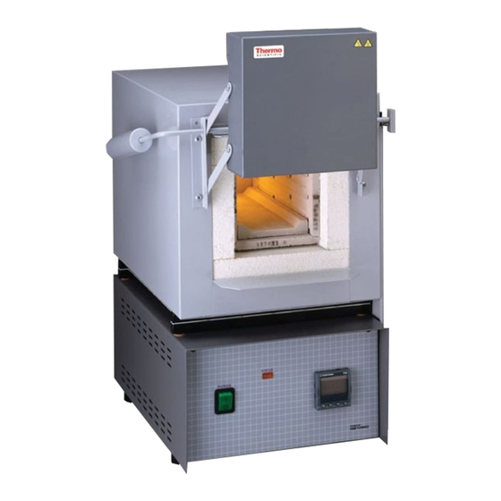
Installation and Operation Manual
Thermo Scientific Thermolyne Furnace
Benchtop Industrial/
Type FD1500M,
Type Models:
FD1530M, FD1530MCN,
FD1530M-33, FD1535M,
FD1540M, FD1540MCN,
FD1540M-33, AND
FD1545M.
1
Table of
Contents
Previous
Page
Next
Page
1
2
3
4
5
Advertisement
Table of Contents
Need help?
Do you have a question about the FD1530M and is the answer not in the manual?
Ask a question
Questions and answers
Related Manuals for Thermo Scientific FD1530M
Furnace Thermo Scientific FD1535M Installation And Operation Manual
Thermolyne furnace benchtop industrial/ type fd1500m (45 pages)
Furnace Thermo Scientific F6000 Operation Manual
(62 pages)
Furnace Thermo Scientific FB1300 Installation And Operation Manual
Thermolyne furnace small benchtop muffle (34 pages)
Furnace Thermo Scientific 1700 Operation Manual And Parts List
(20 pages)
Furnace Thermo Scientific F30400 Installation And Operation Manual
Thermolyne furnace large tabletop muffle/ atmosphere controlled ashing (70 pages)
Furnace Thermo Scientific FB1310M Installation And Operation Manual
Thermolyne furnace small benchtop muffle (34 pages)
Furnace Thermo Scientific FB1310M-33 Installation And Operation Manual
Thermolyne furnace small benchtop muffle (34 pages)
Furnace Thermo Scientific FB1315M Installation And Operation Manual
Thermolyne furnace small benchtop muffle (34 pages)
Furnace Thermo Scientific BF51728 Installation And Operational Manual
Lindberg/blue m moldatherm 1100 c box furnace (81 pages)
Furnace Thermo Scientific 47900 Installation And Operation Manual
(96 pages)
Furnace Thermo Scientific BF51841C Operation Manual
Laboratory box furnaces (74 pages)
Furnace Thermo Scientific BF51634BC-1 Installation And Operation Manual
(78 pages)
This manual is also suitable for:
Fd1530mcn
Fd1530m-33
Fd1535m
Fd1540m
Fd1540mcn
Fd1540m-33
...
Show all
Fd1545m
Fd1500m
Table of Contents
Print
Rename the bookmark
Delete bookmark?
Delete from my manuals?
Login
Sign In
OR
Sign in with Facebook
Sign in with Google
Upload manual
Upload from disk
Upload from URL


Need help?
Do you have a question about the FD1530M and is the answer not in the manual?
Questions and answers