
Related Manuals for Thermo Scientific FB1300


Summary of Contents for Thermo Scientific FB1300
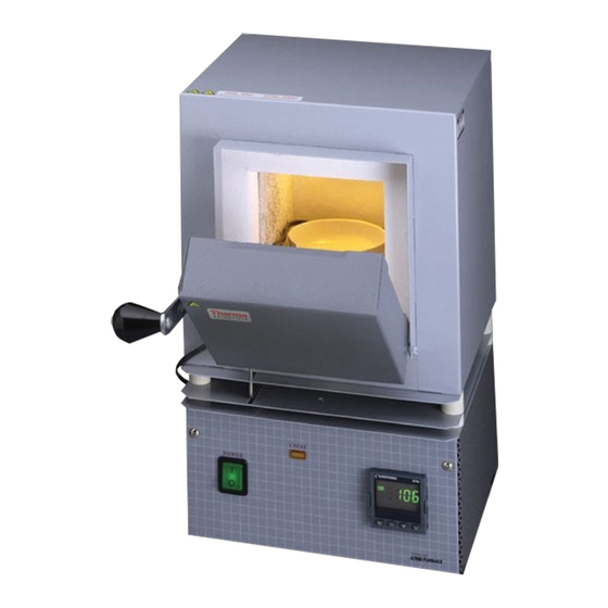
- Page 1 Installation and Operation Manual Thermo Scientific Thermolyne Furnace Small Benchtop Muffle Type FB1300 and FB1400...
- Page 2 © 2010 Thermo Fisher Scientific. All rights reserved. ® “Suva ” is a registered trademark of DuPont. All other trademarks are the property of Thermo Fisher Scientific Inc. and its subsidiaries.
-
Page 3: Table Of Contents
Table of Contents Safety Information ..............................3 Important Information............................3 Warnings ..............................4 Introduction................................5 Intended Use ..............................5 General Usage..............................5 Principles of Operation ..........................5 General Specifications ............................6 Unpacking ................................8 Installation ................................9 Site Selection..............................9 Electrical Connections ..........................9 Operation ................................10 Power Switch ..............................10 Cycle Light ..............................10 Door Safety Switch ............................10 Single Setpoint Controller..........................11 Basic Operation ............................11... -
Page 4: Safety Information
Warning the use of this equipment. Warnings alert you to a possibility of personal injury. Your Thermo Scientific Thermolyne FB1300 Model or FB1400 Model Furnace has been designed with function, reliability, and safety in Caution mind. It is your responsibility to install it in con- Cautions alert you to a possibility of damage to the equipment. - Page 5 AFETY NFORMATION Please note the following WARNINGS: WARNING This warning is presented for compliance with California Proposition 65 and other regulato- ry agencies and only applies to the insulation in this product. This product contains refracto- ry ceramic, refractory ceramic fiber or fiberglass insulation, which can produce respirable dust or fibers during disassembly.
-
Page 6: Introduction
Introduction Intended Use The FB1300 Model and FB1400 Model fur- naces are general purpose laboratory and heat treating furnaces. For optimum element life, observe the following temperature ranges: 100°C (212°F) to 982°C (1800°F) for continuous use, or from 982°C (1800°F) to 1100°C (2012°F) for intermittent use. -
Page 7: General Specifications
General Specifications FB1300 Models Dimensions: (handle not included) Chamber: 4” W x 3.75” H x 4.5” D (10.2 x 9.5 x 11.4 cm) Overall : 7.9” W x 13.8” H x 8.5” D (20.0 x 34.9 x 21.6cm) Chamber volume: 76 cu. in. (1.3 liters) Weight: 15.7 lb. - Page 8 ENERAL PECIFICATIONS...
-
Page 9: Unpacking
Unpacking 1. Visually check for any physical damage to the shipping container. 2. Inspect the equipment surfaces that are adjacent to any damaged area. 3. Open the furnace door and remove the packing material from inside the furnace chamber. 4. Vacuum the chamber prior to use to remove the insulation dust due to shipment. -
Page 10: Installation
Installation Site Selection Caution Install furnace on a sturdy surface and allow Be sure ambient temperature does not adequate space for ventilation. exceed 40°C (104°F). The recommended ambient temperature is 17°C - 27°C. Ambients above this level may result in Electrical Connections damage to the controller. -
Page 11: Operation
Operation, All Modes Power Switch Warning Both the ON/OFF power switch and the digital To avoid personal injury do not use in the display will illuminate when power is switched presence of flammable or combustible ON. The furnace will begin to heat to the con- chemicals;... -
Page 12: Single Setpoint Controller
Single Setpoint Controller Temperature The single setpoint model furnace controller Output 2 Output 1 Display is a single setpoint controller which provides a single digital display to indicate the current chamber temperature or setpoint temperature. This temperature controller features sensor break protection and self-tuning capability. -
Page 13: To View The Display Units
INGLE ETPOINT CONTROLLER desired setpoint value is displayed and then release the button. A few seconds after the button is released, the controller will accept the new value and revert to the HOME DISPLAY. To View the Display Units From the HOME DISPLAY press the SCROLL button. -
Page 14: Alarms
INGLE ETPOINT ONTROLLER Atun List tunE: One-shot autotune enable. Pid List Pb: Proportional band (in display units). ti: Integral time in seconds. td: Derivative time in seconds. ACCS List Code: Access code (Code need- ed to enter or change the other configuration parameters which are not normally accessi- ble.) Not accessable. -
Page 15: Sensor Break Protection
INGLE ETPOINT CONTROLLER Sensor Break Protection This controller provides sensor break protection in the event the thermocouple opens. If an open ther- mocouple condition occurs, the digital display will blink “S.br” and the power to the heating element will be shut OFF (Cycle light will extinguish). Over-Temperature Protection (OTP) The OTP will be in effect during any alarm condi-... - Page 16 INGLE ETPOINT ONTROLLER 3. Press the SCROLL button. Display will read, “tunE.” 4. Press the UP or DOWN button to select, “on.” Note “Stat” and “Sp.rr” in Sp list must be 5. Simultaneously press the PAGE and set to OFF or “tunE” will not initiate. SCROLL buttons to return to the HOME DISPLAY.
-
Page 17: Furnace Loading
Furnace Loading • For best results of furnace loading, use less than two-thirds of any dimension of Caution the chamber. Maintain a 3/4" clearance Do not overload your furnace chamber between the load and the sides of the or allow the load to touch the thermo- chamber. -
Page 18: Preventive Maintenance
Preventive Maintenance Contamination is a major cause of element failure, therefore, when possible, remove the fume forming Warning material before heating (e.g., cleaning cutting oil Before using any cleaning or from tool steel). decontamination method except those recommended by the manu- The resistance wire is high-grade nickel-chromium. -
Page 19: Troubleshooting
Troubleshooting Problem Possible Causes Corrective Action The furnace does not heat No power. Check power source and fuses or (CYCLE light does not illuminate). breakers. Defective electrical hookup. Repair electrical hookup. Thermocouple has oxidized and Replace thermocouple. opened the circuit. (Open thermocouple is indicated on the display as a temperature of 0-5 degrees). -
Page 20: Maintenance And Servicing
Maintenance and Servicing Warning Disconnect the furnace from the power To Replace Heating Element supply before servicing. Refer servic- ing to qualified personnel. 1. Set the furnace on its top. (See Figure 3). Remove thermocouple cover. (If equipped.) Note 2. Remove screw and clamp holding ther- Perform only maintenance described mocouple, then grasp the thermocouple in this manual. - Page 21 AINTENANCE AND ERVICING 6. Remove the back insulation block by open- ing the door and gently pushing it out. Support this insulation block while removing it, as it is quite soft and easily crumbled at the edges. 7. Remove bottom cover to obtain access to terminals.
- Page 22 AINTENANCE AND ERVICING Make the bend 90°, avoiding excessive bend- ing. (The element wires will be exposed at the corner thus formed. This will not affect its life or performance.) 13. Bend the other side of the element. 14. Place the hearth plate across the open end of the ‘’U”...
-
Page 23: To Replace Thermocouple
AINTENANCE AND ERVICING about 1-1/2" into the chamber. Make sure porcelain insulator is in place for the ther- mocouple to pass through on the steel back plate. Replace clamp and screw. (Excessive scaling, pitting, or cracks are some indications that the thermocouple may need to be replaced.) 20. -
Page 24: To Replace Insulation
AINTENANCE AND ERVICING 7. Thread the thermocouple through the hole in the base which has a nylon insulator, replace clamp and screw. 8. Bend the thermocouple sharply toward ter- minal block. 9. Secure the two yellow wires marked “+” together on the terminal block. Secure the two red wires “-”... - Page 25 AINTENANCE AND ERVICING 6. Disconnect thermocouple leads from terminal block. 7. Remove four nuts holding control section to furnace chamber. 8. Remove the ground nut. 9. Remove the control section from the furnace Note chamber. Remove plates, screws, spacers Identify or mark wires disconnected to ensure proper placement and connec- and nuts.
-
Page 26: To Replace Door Switches
AINTENANCE AND ERVICING 18. Thread the element leads and ceramic bushings through the bottom plate. Bend the leads so they lie close to the refractory plate and the bottom insulation block. (The easiest and safest way to do this is to press the wire flat with a stick or blunt pusher. -
Page 27: To Replace Solid State Relay
AINTENANCE AND ERVICING Warning To Replace Solid State Relay Disconnect furnace from power supply before servicing. 1. Place furnace upside down and remove the bottom cover. 2. Disconnect the wires from the solid state relay. Identify or mark the wires disconnect- ed to ensure proper placement and connec- tion when re-installing. -
Page 28: Wiring Diagram
Wiring Diagrams FB 1400 models FB1300 models... -
Page 29: Exploded View
Exploded View... - Page 30 XPLODED...
-
Page 31: Replacement Parts List
Door Switches (all models) SWX163 Control (FB1300M & FB1400M models except FB1410M-33) 1 CN71X81 Control (FB1400M-33 model only) CN71X101 Insulation Btm (all FB1300 models) JC44X1 Insulation Btm (all FB1400 models) JC48X2 Insulation Back (all FB1300 models) JC44X4 Insulation Back (all FB1400 models) -
Page 32: Ordering Procedures
Ordering Procedures Please refer to the Specification Plate for the complete model number, serial number, and series number when requesting service, replacement parts or in any corre- spondence concerning this unit. All parts listed herein may be ordered from the Thermo Scientific dealer from whom you purchased this unit or can be obtained promptly from the factory. - Page 33 Important For your future reference and when contacting the factory, please have the following information readily available: Model Number: Serial Number: Date Purchased: The above information can be found on the dataplate attached to the equipment. If available, please provide the date purchased, the source of purchase (manufacturer or specific agent/rep organization), and purchase order number.
- Page 34 LT1256X1 Rev. B...
Need help?
Do you have a question about the FB1300 and is the answer not in the manual?
Questions and answers