
Related Manuals for Lissmac COMPACTCUT 905 P/T


Summary of Contents for Lissmac COMPACTCUT 905 P/T
- Page 1 OPERATING MANUAL FLOOR SAW COMPACTCUT 905 P/T LISSMAC Maschinenbau GmbH Lanzstrasse 4 D-88410 Bad Wurzach Telephone +49 (0) 7564 / 307-0 Telefax +49 (0) 7564 / 307-500 lissmac@lissmac.com www.lissmac.com 1/80...
- Page 2 2/80...
- Page 3 Imprint The operating manual is valid for: LISSMAC Floor saw • COMPACTCUT 905 P/T Manufacturer: LISSMAC Maschinenbau GmbH Lanzstraße 4 D - 88410 Bad Wurzach Phone: +49 (0) 7564/307 - 0 Fax: +49 (0) 7564 / 307 – 500 lissmac@lissmac.com www.lissmac.com...
- Page 4 FUNDAMENTAL SAFETY NOTES Warning notes and symbols in this manual SIGNAL WORD Type and source of the endangerment Consequence with non-observance Measure, in order to avert the endangerment. The signal word behind the danger symbol refers to the degree of the endangerment: DANGER This signal word designates an extremely dangerous situation.
- Page 5 The following warning signs and safety notes are used: Read the operating manual. Wear hearing protection. Wear safety goggles. Wear safety gloves. Wear a protective helmet. Wear a dust mask. Wear suitable work clothes and wash dusty clothes. Attachment points for crane transport. Remove the ignition key prior to work on the device.
- Page 6 Automatic start-up of the cutting tool during motor start. Suffocation hazard from poisonous exhaust gases. Crush hazard from moving equipment. No displacement with rotating tool. No use of high pressure cleaners. No use by unauthorized persons. No smoking. No maintenance activities when the motor is running. Running direction of the saw blade.
- Page 7 In addition to this operating manual, further documentations from the respective manufacturer of individual components of the machine are available: Operating manual fuel motor LISSMAC does not assume responsibility for the completeness of further documentations or liability with respect to their completeness. Changes and reservations We strive for correctness and topicality of this operating manual.
- Page 8 Notes 8/80...
-
Page 9: Table Of Contents
Table of contents 1. Features & Benefits ....................... 11 2. General safety notes ...................... 12 2.1. Principle intended use ....................12 2.2. Organizational measures ....................13 2.3. Choice of personnel and - qualification; fundamental obligations ........14 2.4. Safety notes regarding the operating phases ..............14 2.4.1. - Page 10 7.10. Troubleshooting ......................53 7.11. Torque settings of screw connections ................54 7.12. Maintenance plan ......................55 8. Tools ..........................56 9. WARRANTY ........................57 10. Spare parts list ......................58 10.1. Steering ........................58 10.2. Front axle ........................59 10.3.
-
Page 11: Table Of Contents 1. Features & Benefits
1. FEATURES & BENEFITS The floor saw convinces through the innovative dry cutting process. The cutting surface is contaminated by saving cooling water and it can be processed faster. The use of a dry floor saw thus accelerates the entire on- site sequence and additionally saves disposal costs. -
Page 12: General Safety Notes
(have them removed). Intended use The LISSMAC floor saw is a floor cutting-off machine and is exclusively intended for cutting joints in concrete or asphalt without water. Cutting comprises saw blades. The floor saw may be operated by one person only. -
Page 13: Organizational Measures
2.2. Organizational measures The operating manual must be kept at hand for every person at the place of work of the floor saw. Additions to the operating manual are generally accepted legal and other obligatory regulations for accident prevention and for environmental protection, which must be observed and instructed. Such obligations can also relate to e. -
Page 14: Choice Of Personnel And - Qualification; Fundamental Obligations
2.3. Choice of personnel and - qualification; fundamental obligations Operators must be at least 18 years of age and be mentally and physically capable to operate the floor saw. All personnel working with of the floor saw must be assigned in writing by the employer first. Specify responsibilities of the personnel for operating, preparing, maintaining and repairing. -
Page 15: Commissioning
2.4.2. Commissioning The running direction of the saw blade must be observed when using the saw blade. The cutting process must always be up-cutting. Protect the hands from sharp edges when inserting the saw blade. Ensure that the underground on which one cuts fulfills the load capacity. All obstacles must be removed from the cutting area and good lighting must be ensured. -
Page 16: Moving The Floor Saw
2.4.4. Maneuvering the floor saw Maneuvering of the floor saw may only be carried out when the saw blade is standing still. Before leaving the operating position at the floor saw, the engine must be stopped and the saw blade must stand still. -
Page 17: Electrical Energy
2.5.2. Electrical energy Only use original fuses with prescribed rating. The floor saw must be switched off immediately with malfunctions! Electrical work may only be carried out by examined and qualified technical personnel. The electrical equipment of a machine is must be inspected/checked regularly. Defects, such as loose connections or damaged cables, must be eliminated immediately. -
Page 18: Packing And Storage
2.7. Packing and storage In order to ensure sufficient protection during dispatch and transport, the machine and its components were packed carefully. When the machine has been received, it should be checked for damages. The packing of the device consists of recyclable materials. Please place these into the collection containers for recycling. -
Page 19: Device Description
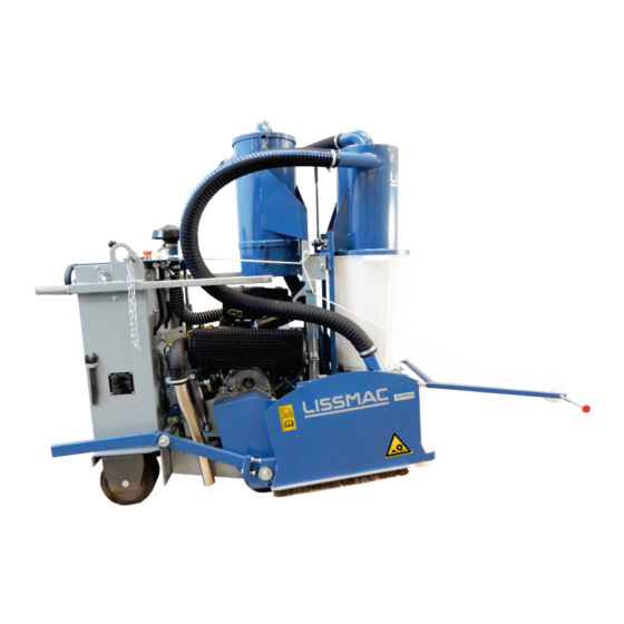
3. DEVICE DESCRIPTION 3.1. Designation of the machine parts Pos. 1 Blade guard Pos. 8 Dust container Pos. 2 Drive motor Pos. 9 Pre-cyclone (coarse separation) Pos. 3 Steering bars Pos. 10 Main cyclone with dust filter (fine separation) Pos. 4 Holding chain for blade guard Pos. -
Page 20: Protection Device
Pos. 12 Steering wheel Pos. 18 Throttle for the lowering speed of the saw blade Pos. 13 Forward, neutral and backwards Pos. 19 EMERGENCY STOP button Pos. 14 Engine Air filter warning lamp Pos. 20 Air filter cover Pos. 15 Oil warning lamp Pos. -
Page 21: Technical Data
3.3. Technical data COMPACTCUT 905 P/T Cutting depth 100 mm right Saw blade diameter 350 mm Saw blade width 20 mm Partial circle / saw blade 92 mm / 25.4 mm reception Blade lifting Hydraulically with lowering valve Saw shaft speed... -
Page 22: Sound Power Level
Wear your personal hearing protection The measured sound power level L 93.5 dB(A) The emission sound pressure at the workplace L amounts to: COMPACTCUT 905 P/T 93.6 dB(A) The guaranteed sound power level L amounts to: COMPACTCUT 905 P/T 104 dB(A) The values were determined by a sound emission measurement. -
Page 23: Commissioning
4. COMMISSIONING 4.1. Connections and operating materials Motor oil The engine is filled with motor oil by the manufacturer. Only oil that is approved by the manufacturer may be used. For usual applications 10W-30. Special specifications are contained in the operating manual of the fuel motor. Fuel The floor saw must be filled with lead-free gasoline (95 octane). -
Page 24: Parking Brake
4.3. Parking brake WARNING Unintentional position change of the machine Injuries through unintentional rolling away of the machine. In order to secure the floor saw against rolling away unintentionally, the parking brake must be used before the operator leaves the machine. Calibration The brake pressure of the parking brake (pos. -
Page 25: Tool (Saw Blade) Installation / Exchange
4.5. Tool (saw blade) installation / exchange WARNING Cutting injury and danger of entanglement at the rotating tool Cutting injuries, separation of limbs and burns by the rotating tool can be the result. Removing or opening the blade guard or interfering with the rotating saw blade is prohibited ... -
Page 26: Saw Blade Installation / Change
4.6. Saw blade installation / change WARNING Cutting injury and danger of entanglement at the rotating saw blade Touching the rotating saw blade can result in cutting injuries, separation of limbs and burns. Removing or opening the blade guard or interfering with the rotating saw blade is prohibited ... - Page 27 Sequence Retain the blade guard at the top with the chain and the hook (pos.1) Remove the screw at the pressure disc with the tool kit and take out the pressure disc Take off the old saw blade (ATTENTION: the blade is very hot after cutting!) ...
-
Page 28: Conversion Flush Cut
4.7. Flush cut conversion For flush cutting, the tool must be fastened to the flush-cut flange with 6 countersunk screws (see below) Additionally, the floor brush must be replaced with the flush wall (WB) brush at the bottom of the blade guard. For this, lift the snap lock at the front at the blade guard and remove the brush. - Page 29 Individual parts: flush-cut flange – 3 pieces washers 1x3 mm + 2x2 mm 6 pieces Allen- head bolts M8x35 mm – 6 pieces countersunk screws M8x20 mm View: flush-cut flange with M8x35 View: base flange on cutting shaft tightened securely on the base flange View: blade fastened to flush-cut flange View:...
-
Page 30: Drive Belt Turbine / Drive
4.8. Drive belt turbine / drive WARNING Cut and crush hazard from rotating belt drive Danger of entanglement for body parts and clothing when opening and removing the belt cover. Removal or opening of the belt cover or touching the rotating belt drive are prohibited ... -
Page 31: Drive Belt Cutting Shaft
4.9. Drive belt cutting shaft WARNING Cut and crush hazard from rotating belt drive Danger of entanglement for body parts and clothing when opening and removing the belt cover. Removing or opening of the belt cover or the intervention in the rotating belt drive is prohibited ... -
Page 32: Transport
5. TRANSPORT 5.1. Transport position WARNING Crush hazard from unsecured machine Injuries through unintentional position change of the machine or falling of parts. Only transport the floor saws in the transport position Secure the floor saw via the attachment point ... -
Page 33: Moving With The Crane
5.2. Moving with the crane WARNING Suspended loads Danger of injury through falling parts. Do not step under raised machines or parts Only use undamaged lifting devices with sufficient load capacity and length The machine may only be moved in the transport position ... -
Page 34: Fastening For Transport
5.3. Fastening for transport WARNING Crush hazard from sliding or tilting of the machine Persons can be crushed through unintentional position changes of the machine. Only transport the machine in transport position Secure the machine via suitable attachment points ... -
Page 35: Operation
6. OPERATION 6.1. Safety • The floor saw may be operated by one person only. General rules Banish other persons from the work area or create a barrier. • Never start the machine when the saw blade stands vertically on the floor. The drive is overloaded thereby. - Page 36 CAUTION Burn hazard Motor parts become hot during operation and can cause burns Avoid contact with the skin Wear personal protection equipment Leave the motor to cool down before work on the device 36/80...
-
Page 37: Start Preparations
6.2. Start preparations NOTICE Cutting without obstacles Damage of articles located in the cutting area or the saw blade. Remove all obstacles from the cutting area and ensure good lighting. The cutting sequence can be marked by a marking spray for the orientation of the cutting sequence. The following conditions must be fulfilled in order to use the floor saw securely and as intended: ... -
Page 38: Starting And Stopping The Machine
6.3. Starting and stopping the machine WARNING Automatic start-up of the cutting tool The tool rotates as soon as the motor is running. It cannot be decoupled. Serious injury on contact with the rotating saw blade or belt drive. Always keep the greatest possible safety margin to the saw blade. ... -
Page 39: Setting-Up And Moving The Floor Saw
6.4. Setting-up and moving the floor saw WARNING Cut hazard from rotating saw blade Clothing can become entangled and limbs can be separated when touching the rotating saw blade. All displacement of the machine outside the cutting area shall be carried out with the tool not ... -
Page 40: Cutting With The Floor Saw
6.5. Cutting with the floor saw NOTICE The surface to be sawn should not be excessively wet, as the dust extraction device can clog otherwise. Ensure a straight cutting process, in order to avoid jamming of the saw blade. Positioning ... -
Page 41: Dust Extraction
6.6. Dust extraction CAUTION Burn hazard The cyclone separator, the blade guard and the collected dust are very hot. Burns can result during contact. Avoid contacting the cyclone separator, that blade guard and the extracted dust Leave the machine to cool down ... - Page 42 As a large amount of dust is produced by the cutting of a dry surface, it is important that the dust extraction system works optimally. The machine is equipped with two cyclone separators. The large pre-separator takes up approx. 95% of the cutting dust in a plastic container. The downstream cyclone is provided with a dust filter cartridge and the remaining dust falls into the removable lower container.
-
Page 43: Depth Adjustment
6.7 Depth scale NOTICE Always lower the tool slowly in order to avoid damages. Adjusting cutting depth takes place via the hydraulic system. A slow, counterclockwise rotation at the throttle valve (pos. 1), lowers the cutting arm with the diamond saw blade to the desired cutting depth. -
Page 44: Inclined Position Of The Saw Blade
6.7. Inclined position of the saw blade Adjusting Loosen the screw (pos. 1) with the hexagon wrench SW 22 (tool kit) solve Incline the floor saw up to 5° on the control panel via the pivot lever (pos. 2) ... -
Page 45: Maintenance
7. MAINTENANCE 7.1. Maintenance WARNING Danger of injury through rotating parts Serious injuries can be inflicted by a rotating saw blade or belt drive. Maintenance and repairs may only take place when the machine is switched off Maintenance and repairs may only be carried out by qualified personnel ... -
Page 46: Tightening The Drive Belts
7.2. Tightening the drive belts Only use the listed belts Blade drive 1 piece of poly V belt 16 PL1074 Lw. Re-tighten the poly V belt (wedge rib belt) between the motor and the cutting shaft when slipping through or replace if necessary. Pretension the new belt in such a manner that one can still press it in by hand by nearly 1 cm /1/2 in. -
Page 47: Lubrication Points
7.3. Lubrication points WARNING Danger of injury through movable parts Serious injuries can be inflicted by a rotating saw blade, fan or belt drive. Maintenance and repairs may only take place when the machine is switched on Maintenance and repairs may only be carried out by qualified personnel The machine must be secured against switching on by other persons ... - Page 48 Inclination adjustment Lubricate the threaded rod of the inclination adjustment monthly Inclination adjustment Lubricate the pivot bearing monthly Belt tensioner Lubricate the belt tensioner monthly Remove the service cover at the rear of the machine with a screwdriver, in order to reach the internal lubrication points.
-
Page 49: Fuses
7.4. Fuses Standard motor vehicle plug-in fuses are used according to ISO 8820-3 (ATO, blade type). Protection Rated current Function Holder 50 A Motor/Main 7.5. Battery 12V 28Ah (20h) (exchange only with the same type) 49/80... -
Page 50: Warning Lamps
7.6. Warning lamps NOTICE Absolutely observe error messages Warning lamps indicate an error in the system. In order to avoid damages to the machine, the displayed error must be rectified immediately. The oil level warning lamp glows red when the ignition is switched on. It goes out after a successful starting process. -
Page 51: Checking Engine Oil Level
7.8. Checking engine oil level Place the machine on a horizontal underground Activate the parking brake Stop the engine and pull out the key Attention: Mufflers and motor parts become very hot during operation. Let the motor cool down. Avoid contact. Wear protective gloves. Sequence ... -
Page 52: Check The Oil Level Of The Hydraulics
7.9. Check the oil level of the hydraulic system Drive The hydraulic oil tank for the drive (pos. 1) is seated above the motor and has an embossed fill level mark. The fill level must always be above MIN. • Clean the filling area, unscrew the lid and refill hydraulic fluid SOW 20W20. Lifting of the saw arm The hydraulic oil tank for lifting the saw arm (pos. -
Page 53: Troubleshooting
7.10. Troubleshooting Measures must be taken, so that an unintentional restart by others is not possible! Maintenance and service work may only be carried out by qualified technical personnel! NOTICE The following points must be checked first with cutting problems: •... -
Page 54: Torque Settings Of Screw Connections
7.11. Torque settings of screw connections Grade: 10.9 12.9 Dimension max. tightening torque in Nm max. tightening torque in Nm max. tightening torque in Nm 11.2 11.3 16.5 19.3 27.3 40.1 46.9 1057 1136 1329 1176 1674 1959 1597 2274 2662 54/80... -
Page 55: Maintenance Plan
7.12. Maintenance plan This section shall serve as proof maintenance already performed and as service booklet. All maintenance and service work must be entered as proof. Machine/type: Serial number/year of manufacture: Date Implemented maintenance or service work Date/signature 55/80... -
Page 56: Tools
*The device is only suitable for concrete cuts to a limited extent, as concrete should be cut wet. The prices of the tools can be determined in the LISSMAC sales booklet. This sales booklet can be obtained from the manufacturer at any time. -
Page 57: Warranty
9. WARRANTY The warranty for this machine is 12 months. For the wear parts listed in the following, warranty is only granted if the wear is not due to operation. Wear parts are those parts, which are subject to an operational wear with an intended use of the machines. The wear time cannot be defined in a uniform manner, it differs according to the usage intensity. -
Page 58: Spare Parts List
10. SPARE PARTS LIST 10.1. Steering Spare part Pos. Art. no. Designation Specification Piece recommendation STEERING GEAR Q40 1:20 MOUNTING PLATE ∅ 125 SPACER RING STEERING WHEEL SHAFT TO THE STEERING WHEEL ∅ 25X2.5X12 GROOVED BALL BEARING 6004 2RS ∅ 50X3 SLEEVE DISK CUP SPRING... -
Page 59: Front Axle
10.2. Front axle Spare part Pos. Art. no. Designation Specification Piece recommendation FRONT AXLE FLANGE BEARING UCFL 205 LEVER HEAVY-DUTY DOWEL PIN 5X 40 WHEEL BOLT L= 62 MM SLEEVE 25/2X 14 MM WASHER COUNTERSUNK SCREW M8 X 20 DIN 799L COUNTERSUNK SCREW M12 X 25 DIN 799L WHEEL BOLT L= 48 mm... -
Page 60: Inclination
10.3. Inclination Spare part Pos. Art. no. Designation Specification Piece recommendation Bearing plate Cylinder bush 35/ 45 x 35 Spring washer Countersunk screw M10x30 DIN 7991 Bearing block Pivot lever Locking screw to the pivot lever 60/80... -
Page 61: Spindle For The Inclination
10.4. Spindle for the inclination Spare part Pos. Art. no. Designation Specification Piece recommendation Spindle nut Spindle Joint head Housing bearing UCUP 202 Crank Rotatable handle to the crank 61/80... -
Page 62: Feed Drive
10.5. Feed drive Spare part Pos. Art. no. Designation Specification Piece recommendation Transmission housing Pinion to the hydrostat Z=20 module 1.5 Gear wheel Z=100 module 1.5 Shaft Spacer sleeve set Ball bearing 6204 2RS Chain wheel ½ x 5/16“ Z=10 Chain tensioner complete Roller chain ½... -
Page 63: Drive
10.6. Drive Spare part Pos. Art no. Designation Specification Piece recommendation EATON Hydrostat ∅ 120 mm Adjusting lever to the hydrostat CCW ∅ 205 mm V-belt pulley Fan wheel made from nylon Adjusting lever Magura Spring plate Fastening plate ∅ 2.0x1800 mm Bowden cable complete without Strand to the bowden cable... -
Page 64: Saw Arm Lift Drive
10.7. Saw arm lift drive Spare part Pos. Art. no. Designation Specification Piece recommendation HPI micro unit Hydraulic cylinder Cylinder fastening Nut for the cylinder fastening Tension spring 26/2/2 Hollow screw M14x1.5 Hollow screw G1/4 “ Hollow screw G1/4 “long Lowering valve 9N 600S (C40-059) Check valve... -
Page 65: Saw Arm
10.8. Saw arm Spare part Pos. Art. no. Designation Specification Piece recommendation Bearing plate Cutting arm Intermediate washer brass Bearing ring brass Belt protection Support for the exhaust hood 65/80... -
Page 66: Cutting Shaft
10.9. Cutting shaft Art. no. Spare part Pos. Designation Specification Piece LISSMAC recommendation Bearing shaft Deep groove ball bearing 6207 LLB Spacer sleeve Ø 42 x 3.5 x 40 Circlip Poly V- belt pulley / cutting shaft Circlip without Collar nut... -
Page 67: Tension Roller / Cutting Drive
10.10. Tension roller / cutting drive Spare part Pos. Art. no. Designation Specification Piece recommendatio Roller Ø 60 x 85 Grooved ball bearing 6204 2RS Circlip Shaft to the belt tensioner Hexagon screw M10x16 DIN 933 Nut to the screw tension roller Tension roller complete 67/80... -
Page 68: Deflection / Tension Roller
10.11. Deflection / tension roller Spare part Pos. Art. no. Designation Specification Piece recommendatio Countersunk screw M10 x 20 DIN 7991 Deep groove ball bearing 6204 2RS Hexagon screw M12 x 70 DIN 931 Hexagon screw M10 x 30 DIN 933 Cylinder socket 12 / 16x12 Deflection roller... -
Page 69: Motor / Mounting Parts
10.12. Motor / mounting parts Spare part Pos. Art. no. Designation Specification Piece recommendation Mount to the belt protection Venti side Shaft end auxiliary drive complete V-belt pulley SPZ 145 / 80mm Poly V-belt pulley motor Ø75 PL 16 Parallel key to the poly V-belt pulley Wedge ribbed belt 16PL 1074 LW Accelerator cable (Lever control) -
Page 70: Air Filter Motor
10.13. Air filter motor Spare part Pos. Art. no. Designation Specification Piece recommendation Air filter complete Donaldson Air filter main element 373-108 Air filter safety element 373-109 Rain cap Ø52 373-104 Hose to the air filter motor Ø50 x 920 Contamination indicator X77-0050 70/80... -
Page 71: Battery
10.14. Battery Spare part Pos. Art. no. Designation Specification Piece recommendation Battery holder Battery 12 v 28 A Strap for the battery fastening Emergency stop complete ZB4BS54 + ZB4BZ105 Oil control lamp Push button Relay 12 v 70 A to HPI Contamination indicator air filter 71/80... -
Page 72: Housing
10.15. Housing Spare part Pos. Art. no. Designation Specification Piece recommendation V-belt cover Lid rear Spring closure to the lid Perforated plate cover to the hydrostat Cover to the motor Tank Instrument panel without Handle tube figure without Rubber handle figure 72/80... -
Page 73: Steering Rod
10.16. Steering Rod Spare part Pos. Art. no. Designation Specification Piece recommendation Retaining bracket to the steering rod Direction indicator ∅ 80 mm Pointer to the direction indicator Wheel Fork head M10x20 DIN 71751 Depth indicator Joint haed M8x32 DIN 71751 73/80... -
Page 74: Blade Protection
10.17. Blade protection Spare part Pos. Art. no. Designation Specification Piece recommendation ∅ 350 mm Exhaust hood (depicted design may vary) Arm to the exhaust hood Brush on the interchangeable frame ∅ 80 mm Spring clip Wheel Reception bolt to the exhaust hood Brass disk Bearing sleeves Hood fastening... -
Page 75: Fan For The Extraction
10.18. Fan for the extraction Spare part Pos. Art. no. Designation Specification Piece recommendation Bearing block Fan housing Inner ring Fan lid Intake manifold Belt pulley Ball bearing 6205 LLB Spacer sleeve D=30x2,5x70 Spacer sleeve D=30x2,5x5 Spacer sleeve D=30x2,5x17 Shaft Supporting disk Impeller Spring washer... -
Page 76: Cyclone / Pre-Separator
10.19. Cyclone / pre-separator Spare part Pos. Art. no. Designation Specification Piece recommendation Mount to the pre-separator Lever Pre-separator Bucket Filter housing Lid to the filter housing Seal to the lid 1070717 Filter Tightening screw to the filter Handle 76/80... -
Page 77: Rear Axle
10.20. Rear axle Spare part Pos. Art.no. Designation Specification Piece recommendation Rear axle Housing bearing SY30 TF / UCP 206 Chain wheel ½” x 5/16” Z32 Flange GF65 Universal joint HA 100 – 250-65-64-E Bearing ring Bearing sleeve Ф 40x30x30 Bearing plate Steering fork Bearing bolt... -
Page 78: Circuit Diagram
11. CIRCUIT DIAGRAM 78/80... -
Page 79: Original Ec Conformity Declaration
LISSMAC Maschinenbau GmbH, D-88410 Bad Wurzach Machine description: The LISSMAC Floor saw pertains to floor cutting-off machines and is exclusively intended for cutting joints in concrete or asphalt. This machine may only be operated with the integrated dust extraction system. Cutting comprises saw blades, up to a maximum of 350 mm. - Page 80 80/80...
Need help?
Do you have a question about the COMPACTCUT 905 P/T and is the answer not in the manual?
Questions and answers