Table of Contents
Advertisement
Quick Links
Advertisement
Table of Contents

Related Manuals for Jet JWL-1640VS


Summary of Contents for Jet JWL-1640VS
- Page 1 WOOD LATHE JWL-1640VS Original: Operating Instructions Translations: Gebrauchsanleitung Mode d´emploi JPW (Tool) AG Tämplerlistrasse 5 CH-8117 Fällanden Switzerland Phone +41 44 806 47 48 +41 44 806 47 58 www.jettools.com M-719500M 2016 -09...
- Page 2 Déclaration de conformité CE Product / Produkt / Produit: Wood lathe Drechselmaschine Tour à bois JWL-1640VS 719500M Brand / Marke / Marque: Manufacturer / Hersteller / Fabricant: JPW (Tool) AG, Tämperlistrasse 5, CH-8117 Fällanden, Switzerland We hereby declare that this product complies with the regulations Wir erklären hiermit, dass dieses Produkt der folgenden Richtlinie entspricht...
-
Page 3: Table Of Contents
Dear Customer, Many thanks for the confidence you have shown in us with the purchase of your new JET-machine. This manual has been prepared for the owner and operators of a JET JWL-1640EVS wood lathe to promote safety during installation, operation and maintenance procedures. -
Page 4: General Safety Notes
The machine must only be used in a technically perfect Install the machine so that there is sufficient space for safe condition. operation and workpiece handling. When working on the machine, all safety mechanisms and Keep work area well lighted. covers must be mounted. -
Page 5: Remaining Hazards
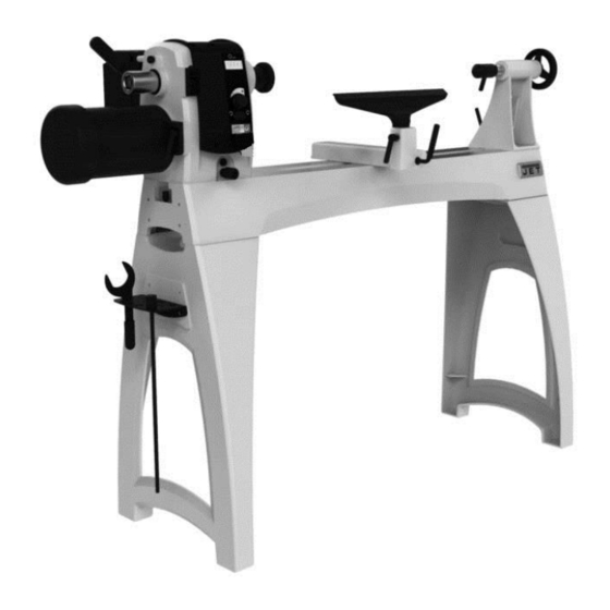
When sanding, remove the tool rest from the machine. Workpieces with cracks may not be used. 4. Machine specifications Remove the chuck key or dowel pins before turning the 4.1 Machine description machine on. Always close the belt cover. Specifications regarding the maximum or minimum size of the workpiece must be observed. -
Page 6: Noise Emission
Overall (LxWxH) 1854 x 1334 x 508 mm Net weight 170 kg Mains 1~230V, PE, 50Hz Output power 1,1 kW (1,5 HP) S1 Reference current Extension cord (H07RN-F): 3x1,5mm² Installation fuse protection Isolation class 4.3 Noise emission Acoustic pressure level (EN ISO 11202): Idling LpA 72,5 dB(A) In operation... - Page 7 Now headstock, tool rest and tailstock can be installed again (Fig 7). Fig 8 Installing bed extension: (JET Option # 719401) The bed extension can be mounted to the upper or lower holes of the lathe. Mounting the extension to the lower holes allows use of the...
-
Page 8: Mains Connection
Insert guard support rod into mounting bracket at rear of headstock. You will have to lift up on spring pin, as shown, to slide guard support rod into mounting bracket. Release spring pin and it will snap into position as you slide support rod farther in. -
Page 9: Starting Operation
Gouge (A, Fig 13), used for rapidly cut raw wood into round stock, for turning bowls and plates, for turning beds, coves 5.5 Starting operation and other detail (Fig 14). You can start the machine with the green ON-button. The red OFF-button on the main switch (B, Fig 1) stops the machine. -
Page 10: Turning Between Centres
6.4 Turning between centres: With a ruler locate and mark the centre on each end. Put a dimple in each end of the shock. Extremely hard woods may require kerfs cut into the spur drive end of stock (see Fig Fig 18-1 Mount the centred workpiece between the spur drive centre and the tailstock mounted live centre (Fig 19) -
Page 11: Bowl Turning
Position the tool rest as close to the workpiece as possible. Tighten locking handles. Fig 23 For turning between centres the tool rest is set approximately Mount the workpiece (A, Fig 24) directly to the face plate 3mm higher than centre line (Fig 20, 21 and 22. using 4 wood screws (C) from the back. -
Page 12: Sanding And Finishing
Try to make one, very light continuous movement from the rim to the bottom of the bowl to ensure a clean, sweeping curve through the workpiece. Move tool support to the exterior to re-define bottom of bowl. 6.6 Sanding and Finishing: Remove the tool rest and begin with a fine grit sandpaper (120 grit) and progress through each grit, using only light pressure. -
Page 13: Headstock Spindle Lock
Loosen the headstock lock handle (A) and pull the index 7.2 Headstock spindle lock plunger (B) to turn the headstock. Push spindle lock pin (P, Figure 27) and rotate spindle slightly until pin engages. Slide plate downward to hold pin in locking position. -
Page 14: Installing Work Holding
7.5 Installing work holding The faceplate is used for tuning bowls. There are a number of holes for mounting the workpiece. Thread the faceplate onto the spindle in a clockwise direction, and tighten two setscrews (E, Fig 30). Fig 32 7.7 Adjusting tailstock Turn the hand wheel (R, Fig 33) clockwise to move tailstock spindle forward. -
Page 15: Adjusting Bed Clamping
To change out a belt or pulley, carefully proceed as follows. headstock and take into a repair station for servicing. If you are uncertain about attempting a belt or pulley change-out, contact JET technical service or take the headstock to an authorized service center. 9. Trouble shooting Motor doesn’t start... -
Page 16: Environmental Protection
Please leave it at a specialized institution. 11. Available accessories Stock number 719401 Bed extension 508mm with tool post extension Refer to the JET-Pricelist for various tools and work holding. Stock number 719001 Tailstock swing away Stock number 719002...
Need help?
Do you have a question about the JWL-1640VS and is the answer not in the manual?
Questions and answers