
Related Manuals for Toshiba RAV-RM1601BTP Series


Summary of Contents for Toshiba RAV-RM1601BTP Series
- Page 1 FILE NO. SVM-18039-2 SERVICE MANUAL SPLIT TYPE INDOOR UNIT <DIGITAL INVERTER> Concealed Duct Type RAV-RM561BTP Series RAV-RM801BTP Series RAV-RM1101BTP Series RAV-RM1401BTP Series RAV-RM1601BTP Series R32 or R410A Revised on June, 2019...
-
Page 2: Table Of Contents
FILE NO. SVM-18039 NOTE A direct current motor is adopted for indoor fan motor in the Concealed Duct Standard Type air conditioner. Caused from its characteristics, a current limit works on the direct current motor. When replacing the high-performance filter or when opening the service board, be sure to stop the fan. If an above action is executed during the fan operation, the protective control works to stop the unit operation, and the check code “P12”... - Page 3 FILE NO. SVM-18039 8. SETUP AT LOCAL SITE AND OTHERS ..........63 8-1. Indoor Unit......................63 8-2. Setup at Local Site / Others ................73 8-3. How to Set up Central Control Address Number ........... 75 9. ADDRESS SETUP..................77 9-1.
-
Page 4: Original Instruction
Toshiba Carrier Corporation or, alternatively, he or she has been instructed in such matters by an individual or individuals who have been trained and is thus thoroughly acquainted with the knowledge related to this work. - Page 5 FILE NO. SVM-18039 Definition of Protective Gear When the air conditioner is to be transported, installed, maintained, repaired or removed, wear protective gloves and ‘safety’ work clothing. In addition to such normal protective gear, wear the protective gear described below when undertaking the special work detailed in the table below.
-
Page 6: Warning Indications On The Air Conditioner Unit
FILE NO. SVM-18039 Warning Indications on the Air Conditioner Unit [Confirmation of warning label on the main unit] Confirm that labels are indicated on the specified positions If removing the label during parts replace, stick it as the original. Warning indication Description WARNING WARNING... -
Page 7: Precaution For Safety
FILE NO. SVM-18039 Precaution for Safety The manufacturer shall not assume any liability for the damage caused by not observing the description of this manual. DANGER Before carrying out the installation, maintenance, repair or removal work, be sure to set the circuit breaker to the OFF position. - Page 8 FILE NO. SVM-18039 Electrical wiring work shall be conducted according to law and regulation in the community and Installation manual. Failure to do so may result in electrocution or short circuit. To connect the electrical wires, repair the electrical parts or undertake other electrical jobs, wear gloves to provide protection for electricians, insulating shoes and clothing to provide protection from electric shocks.
- Page 9 FILE NO. SVM-18039 Connect the cut-off lead wires with crimp contact, etc, put the closed end side upward and then apply a water-cut method, otherwise a leak or production of fire is caused at the users' side. Insulating measures When performing repairs using a gas burner, replace the refrigerant with nitrogen gas because the oil that coats the pipes may otherwise burn.
- Page 10 FILE NO. SVM-18039 When the refrigerant gas leaks, find up the leaked position and repair it surely. If the leaked position cannot be found up and the repair work is interrupted, pump-down and tighten the service valve, otherwise the refrigerant gas may leak into the room. The poisonous gas generates when gas touches to fire such as fan heater, stove or cocking stove though the refrigerant gas itself is innocuous.
- Page 11 FILE NO. SVM-18039 Only a qualified installer or service person is allowed to do installation work. Inappropriate installation may result in water leakage, electric shock or fire. Before starting to install the air conditioner, read carefully through the Installation Manual, and follow its instructions to install the air conditioner.
- Page 12 FILE NO. SVM-18039 Declaration of Conformity Manufacturer: TOSHIBA CARRIER (THAILAND) CO., LTD. 144 / 9 Moo 5, Bangkadi Industrial Park, Tivanon Road, Amphur Muang, Pathumthani 12000, Thailand TCF holder: TOSHIBA CARRIER EUROPE S.A.S Route de Thil 01120 Montluel FRANCE Hereby declares that the machinery described below:...
- Page 13 FILE NO. SVM-18039 Specifications Sound power level (dBA) Model Weight (kg) Cooling Heating ∗ ∗ RAV-RM561BTP-E ∗ ∗ RAV-RM801BTP-E ∗ ∗ RAV-RM1101BTP-E ∗ ∗ RAV-RM1401BTP-E ∗ ∗ RAV-RM1601BTP-E ∗ ∗ RAV-RM561BTP-TR ∗ ∗ RAV-RM801BTP-TR ∗ ∗ RAV-RM1101BTP-TR ∗ ∗ RAV-RM1401BTP-TR ∗...
-
Page 14: New Refrigerant (R32 Or R410A)
FILE NO. SVM-18039 • Refrigerant (R32 or R410A) This air conditioner adopts a refrigerant HFC (R32 or R410A) which does not deplete the ozone layer. 1. Safety Caution Concerned to Refrigerant R32 or R410A The pressure of R32 or R410A is high 1.6 times of that of the former refrigerant (R22). Accompanied with change of refrigerant, the refrigerating oil has been also changed. - Page 15 FILE NO. SVM-18039 4. Tools 1. Required Tools for R32 or R410A Mixing of different types of oil may cause a trouble such as generation of sludge, clogging of capillary, etc. Accordingly, the tools to be used are classified into the following three types. 1) Tools exclusive for R32 or R410A (Those which cannot be used for conventional refrigerant (R22)) 2) Tools exclusive for R32 or R410A, but can be also used for conventional refrigerant (R22) 3) Tools commonly used for R32 or R410A and for conventional refrigerant (R22)
-
Page 16: Air Ducting Work
FILE NO. SVM-18039 1. AIR DUCTING WORK 1-1. Static Pressure Characteristics RM56 type RM80 type Standard air volume: 800 m³/h Standard air volume: 1200 m³/h Lower limit of external Lower limit of external static pressure (120 Pa) static pressure (120 Pa) High Upper limit of Upper limit of... -
Page 17: Construction Views (External Views)
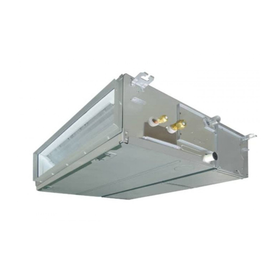
FILE NO. SVM-18039 2. CONSTRUCTION VIEWS (EXTERNAL VIEWS) RAV-RM561BTP∗, RAV-RM801BTP∗, RAV-RM1101BTP∗, RAV-RM1401BTP∗, RAV-RM1601BTP∗ RM56 type RM80 type RM110, 140, 160 type RM56 type RM80 type RM110, 140, 160 type - 17 -... - Page 18 FILE NO. SVM-18039 RM56 type RM80 type RM110, RM140, RM160 type - 18 -...
-
Page 19: Wiring Diagram
FILE NO. SVM-18039 3. WIRING DIAGRAM - 19 -... -
Page 20: Specifications Of Electrical Parts
FILE NO. SVM-18039 4. SPECIFICATIONS OF ELECTRICAL PARTS Concealed Duct Type Parts name Type Specifications Fan motor (RM561BTP) ICF-340W150-2 Output (Rated) 150W, 220-240V Fan motor (RM801BTP) ICF-340W150-1 Output (Rated) 150W, 220-240V Fan motor (RM1101BTP / RM1401BTP / RM1601BTP) ICF-340W250-1 Output (Rated) 250W, 220-240V 218mm Thermo. -
Page 21: Control Block Diagram
FILE NO. SVM-18039 5. CONTROL BLOCK DIAGRAM 5-1. Indoor Controller Block Diagram 5-1-1. In Case of Connection of Wired (Simple) Remote Controller Wired (Simple) heder remote controller (Max. 2 units) Schedule remote controller Display LCD Function setup Display LCD LCD driver Display LED Key switch Function setup... - Page 22 FILE NO. SVM-18039 5-1-2. In Case of Connection of Wireless Remote Controller Indoor unit #1 (Heder) Wireless remote controller Receiver P.C. board Display LED Receive circuit Function setup SW Buzzer Temporary operation SW DC5V Power Remote controller circuit communication circuit (Follower) (Follower) Indoor control P.C.
- Page 23 FILE NO. SVM-18039 5-1-3. Connection of Both Wired (Simple) Remote Controller and Wireless Remote Controller Indoor unit #1 (Heder) Wired (Simple) heder remote controller Wireless remote controller Schedule remote controller (Max. 2 units) Receiver P.C. board Display LED Display Function Display setup driver...
-
Page 24: Control Specifications
FILE NO. SVM-18039 5-2. Control Specifications Item Outline of specifications Remarks When power 1) Distinction of outdoor unit supply is reset When the power supply is reset, the outdoors are distin- guished and the control is selected according to the distinguished result. - Page 25 FILE NO. SVM-18039 Item Outline of specifications Remarks Room temp. 2) Using the CODE No. 06, the setup temperature in heating Shift of suction control operation can be corrected. temperature in heating (Continued) operation SET DATA Setup temp. +0°C +2°C +4°C +6°C correction...
- Page 26 FILE NO. SVM-18039 Item Outline of specifications Remarks Fan speed control 1) Operation with (HH), (H), (L) or [AUTO] mode is carried HH > H+ > H > L+ > out by the command from the remote controller. L > UL 2) When the fan speed mode [AUTO] is selected, the fan speed varies by the difference between Ta and Ts.
- Page 27 FILE NO. SVM-18039 Item Outline of specifications Remarks Fan speed control (Continued) CODE No. 40Pa 30Pa 65Pa 50Pa 80Pa 100Pa 120Pa [5d] 0000 0001 0002 0003 0004 0005 0006 SW501(1)/(2) OFF/ON ON/OFF — OFF/ON — — ON/ON HEAT COOL HEAT COOL HEAT COOL...
- Page 28 FILE NO. SVM-18039 Item Outline of specifications Remarks Freeze preventive control 1) The cooling operation (including Dry operation) is Tcj: (Low temperature release) performed as follows based on the detected Indoor heat exchanger temperature of Tc sensor or Tcj sensor. sensor temperature When [J] zone is detected for 6 minutes (Following figure), the commanded frequency is...
- Page 29 FILE NO. SVM-18039 Item Outline of specifications Remarks High-temp. 1) The heating operation is performed as follows based on the release control detected temperature of Tc sensor or Tcj sensor. • When [M] zone is detected, the commanded frequency is However this control is decreased from the real operation frequency.
- Page 30 FILE NO. SVM-18039 Item Outline of specifications Remarks Frequency <In case of wired remote controller> Command frequency is fixed operation approximately [S7] 1) When pushing [CHK] button for 4 seconds or more, [TEST] is (Test run) displayed on the display screen and the mode enters in Test run mode.
- Page 31 FILE NO. SVM-18039 Item Outline of specifications Remarks Central control 1) Setting at the central controller side enables to select mode selection the contents which can be operated on the wired remote controller. 2) Setup contents • In case of TCC-LINK Central remote controller (TCB-SC642TLE2) [Individual]: Operated by wired remote controller...
- Page 32 FILE NO. SVM-18039 Item Outline of specifications Remarks DC motor 1) When the fan operation has started, positioning of the stator and the rotor are performed. (Moves slightly with tap sound) 2) The motor operates according to the command from the indoor controller.
- Page 33 FILE NO. SVM-18039 Item Outline of specifications Remarks SAVE Save operation 1) Turn on button on the remote controller. Carry out setting operation during stop of 2) During operation of save operation, lights on the the unit; otherwise the wired remote controller. unit stops operation.
-
Page 34: Indoor Print Circuit Board
FILE NO. SVM-18039 5-3. Indoor Print Circuit Board <MCC-1631> - 34 -... - Page 35 FILE NO. SVM-18039 Indoor P.C. Board Optional Connector Specifications (MCC-1631) Function Connector No. Pin No. Specification Remarks Fan output DC12 V Factory default setting: ON when indoor unit in operation and OFF when indoor unit at rest Output CN32 * Fan can be operated on its own by pressing FAN button on remote controller (DN = 31) Start / stop input Start / stop input for HA (J01: In place / Removed =...
-
Page 36: Troubleshooting
FILE NO. SVM-18039 6. TROUBLESHOOTING 6-1. Summary of Troubleshooting <Wired remote controller type> 1. Before troubleshooting 1) Required tools/instruments • screwdrivers, spanners, radio cutting pliers, nippers, push pins for reset switch – • Tester, thermometer, pressure gauge, etc. 2) Confirmation points before check a) The following operations are normal. - Page 37 FILE NO. SVM-18039 <Wireless remote controller type> 1. Before troubleshooting 1) Required tools/instruments • screwdrivers, spanners, radio cutting pliers, nippers, etc. – • Tester, thermometer, pressure gauge, etc. 2) Confirmation points before check a) The following operations are normal. 1. Compressor does not operate. •...
- Page 38 FILE NO. SVM-18039 Outline of judgment When one of the following phenomena appears, an error of the power relay (RY01) is considered; therefore replace the P.C. board. • The operation • The fan stops immediately. After approx. 1minute The screen of the →...
- Page 39 FILE NO. SVM-18039 Lamp indication Check code Cause of trouble occurrence Operation Timer Ready Heat exchanger sensor (TCJ) error ⎫ ⎪ Heat exchanger sensor (TC) error Indoor unit sensor error ⎬ ⎪ Alternate flash Heat exchanger sensor (TA) error ⎭ Discharge temp.
- Page 40 FILE NO. SVM-18039 Others (Other than Check Code) Lamp indication Check code Cause of trouble occurrence Operation Timer Ready — During test run Simultaneous flash Operation Timer Ready Disagreement cool/heat — (Automatic cool/heat setting to automatic cool/heat prohibited mode) Alternate flash - 40 -...
- Page 41 FILE NO. SVM-18039 - 41 -...
-
Page 42: Check Code List (Indoor)
FILE NO. SVM-18039 Check Code List Error mode detected by indoor unit Operation of diagnostic function Judgment and measures Check Status of Cause of operation Condition code air conditioner 1. Check cables of remote controller and communication adapters. No communication from remote Stop Displayed when controller (including wireless) and... - Page 43 FILE NO. SVM-18039 Error mode detected by outdoor unit Operation of diagnostic function Check code Status of Judgment and measures Cause of operation Condition air conditioner Indoor unit Disconnection, short of discharge temp. sensor 1. Check discharge temp. sensor (TD). Displayed when Stop (TD)
- Page 44 FILE NO. SVM-18039 Operation of diagnostic function Check code Status of Judgment and measures Cause of operation air conditioner Condition Indoor unit Displayed when 1. Check outdoor P.C. board. Current detection circuit error Stop error is detected (AC current detection circuit) 1.
- Page 45 FILE NO. SVM-18039 Error mode detected by remote controller or central controller (TCC-LINK) Operation of diagnostic function Judgment and measures Status of Check code Cause of operation Condition air conditioner Power supply error of remote controller, Indoor EEPROM error 1. Check remote controller inter-unit wiring. No communication with master indoor unit 2.
-
Page 46: Diagnostic Procedure For Each Check Code (Indoor Unit)
FILE NO. SVM-18039 6-3. Diagnostic Procedure for Each Check Code (Indoor Unit) Check code [E01 error] Correct inter-unit cable Is inter-unit cable of A and B normal? of remote controller Is there no disconnection or Correct connection of connector. contact error of connector on harness Check circuit wiring. - Page 47 FILE NO. SVM-18039 [E04 error] Is group address setup of Does outdoor operate? Check CODE No. [14]. remote controller correct? Are wiring in indoor unit and Correct wiring and 1, 2, 3 inter-unit cables correct? inter-unit cables. Are wirings of terminal blocks Correct wiring of connector and terminal blocks.
- Page 48 FILE NO. SVM-18039 [E18 error] Correct inter-unit cable Is inter-unit cable of A and B normal? of remote controller. Is there no disconnection or contact error of connector Correct connection of connector. on harness from terminal block Check circuit wiring. of indoor unit? Is group control operation? Check power...
- Page 49 FILE NO. SVM-18039 [L20 error] Are wiring connections to communication lines Correct wiring connection. U3 and U4 normal? Is not the multiple same central Correct central control system address. control system addresses connected? Check central controller (including 1:1 model connection interface) and indoor P.C.
- Page 50 FILE NO. SVM-18039 [P10 error] Is connection of float switch connector Correct connection (Indoor control board CN34) of connector. normal? Does float switch work? Is circuit wiring normal? Check and correct wiring and wire circuit. Does drain pump work? Are connector pins 1 and 2 Is power of at drain pump unit side shorted drain pump turned on? ∗...
- Page 51 FILE NO. SVM-18039 [P12 error] Turn off the power. Correct setting of the static pressure. Is the static pressure setting correct? Change cappacity setting. Is the capacity setting correct? Are not there connections errors or Correct connection of connector. disconnection on connectors CN333 and CN334 of indoor unit P.C.
- Page 52 FILE NO. SVM-18039 [P19 error] Is operation of 4-way valve normal? Are 1.3 to 1.6kΩ applied to (Check the pipe temp., etc. Replace 4-way valve coil. resistance value of 4-way valve coil ? during cooling/heating operation. Defective Check outdoor P.C. board operation. Check outdoor P.C.
- Page 53 FILE NO. SVM-18039 [F02 error] Is connection of TC sensor connector Correct connection of connector. (CN101 on Indoor P.C. board) correct? Are characteristics of Replace TC sensor. TC sensor resistance value normal? ∗ Refer to Charqacteristics-2. Check indoor P.C. board (MCC-1631). Defect →...
- Page 54 FILE NO. SVM-18039 [C06 error] (1:1 model connection interface) Are U3 and U4 communication lines normal? Correct communication line. ∗1 Correct connection of connector. Is connection of connector normal? ∗1 In case of 1:1 model connection interface 1:1 model connection interface (MCC-1440) CN51 and indoor P.C. board CN050. Check connection of A and B terminal blocks.
- Page 55 FILE NO. SVM-18039 [E03 error] (Master indoor unit) [E03 error] is detected when the indoor unit cannot receive a signal from the wired remote controller (also central controller). Check A and B remote controllers and communication lines of the central control system U3 and U4. As communication is impossible, this check code [E03] is not displayed on the wired remote controller and the central controller.
- Page 56 FILE NO. SVM-18039 Temperature – Resistance value characteristic table TA, TC, TCJ, TE, TS, TO sensor TD, TL sensor Representative value Representative value Resistance value (kΩ Ω Ω Ω Ω ) Resistance value (kΩ Ω Ω Ω Ω ) Temperature Temperature (Minimum (Standard...
- Page 57 FILE NO. SVM-18039 Winding Resistance of Fan Motor Part name Checking procedure Concealed Duct type Measure the resistance value of each winding by using the tester. Fan motor ICF-340W150-1, 2 ICF-340W150-2 Position Resistance value (RAV-RM561BTP*) Black – Red 14.8 ± 1.5 ICF-340W150-1 Fan motor inside wiring diagram (RAV-RM801BTP*)
-
Page 58: Replacement Of Service P.c. Board
FILE NO. SVM-18039 7. REPLACEMENT OF SERVICE P.C. BOARD 7-1. Indoort Unit CAUTION ∗∗∗ ∗ BTP-E(TR)> <Model : RAV-RM∗∗ ∗∗∗ ∗∗∗ ∗∗∗ CE CE CE CE CE For the above models, set the CODE No. to “ ” and the setting data 0000 (initial) to “0002” <Note: when replacing the P.C. - Page 59 FILE NO. SVM-18039 [1] Setting data read out from EEPROM The setting data modified on the site, other than factory-set value, stored in the EEPROM shall be read out. Step 1 Push button on the remote controller simultaneously for more than 4 seconds. TEST ∗...
- Page 60 FILE NO. SVM-18039 [3] Writing the setting data to EEPROM The settings stored in the EEPROM of the P.C. board for indoor unit servicing are the factory-set values. Step 1 Push buttons on the remote controller simultaneously for more than 4 seconds. TEST ∗...
- Page 61 FILE NO. SVM-18039 Step 4 Write the on-site setting data to the EEPROM, such as address setting, etc. Perform the steps 1 and 2 above again. 01 01 01 01 01 Step 5 Change the CODE No. (DN) to “ ”...
- Page 62 FILE NO. SVM-18039-2 Table 1 Item Setting data Factory-set value Filter sign lighting time Depending on Type Filter pollution level 0000: Standard Central control address 0099: Not determined Heating suction temperature shift 0002: +2°C Cooling only 0000: Heat pump Type Depending on model type Indoor unit capacity Depending on capacity type...
-
Page 63: Setup At Local Site And Others
FILE NO. SVM-18039 8. SETUP AT LOCAL SITE AND OTHERS 8-1. Indoor Unit 8-1-1. Test Run Setup on Remote Controller <Wired remote controller> TEST 1. When pushing button on the remote controller for 4 seconds or more, “TEST” is displayed on LC display. ON / OFF Then push button. - Page 64 FILE NO. SVM-18039 8-1-2. Forced Defrost Setup of Remote Controller (For wired remote controller only) (Preparation in advance) TEST Push buttons simultaneously for 4 seconds or more on the remote controller. (Push buttons while the air conditioner stops.) The first displayed unit No. is the master indoor unit address in the group control. Every pushing button, the indoor unit No.
- Page 65 FILE NO. SVM-18039 8-1-4. Function Selection Setup <Procedure> Perform setting while the air conditioner stops. TEST Push buttons simultaneously for 4 seconds or more. The first displayed unit No. is the master indoor unit address in the group control. In this time, fan and louver of the selected indoor unit operate. UNIT LOUVER Every pushing button (button at left side), the indoor unit No.
- Page 66 FILE NO. SVM-18039 Item No. (DN) table (Selection of function) Item Description At shipment Filter sign lighting time} 0000 : None 0002 : 2500H 0002 : 2500H (4-Way/Duct/Ceiling Type) Dirty state of filter 0000 : Standard 0001 : High degree of dirt 0000 : Standard (Half of standard time) Central control address...
- Page 67 FILE NO. SVM-18039 Item Description At shipment Timer set 0000 : Available (Operable) 0000 : Available (Wired remote controller) 0001 : Unavailable (Operation prohibited) Correction of high heat feeling 0000 : None 0001 : Correction 0000 : None Self clean time 0000: None 0000: None 0001: 0.5h to 0.012: 6.0h...
- Page 68 FILE NO. SVM-18039 8-1-4. Cabling and Setting of Remote Controller Control 2-remote controller control <Wired remote controller> (Controlled by 2 remote controllers) How to set wired remote controller as sub remote controller This control is to operate 1 or multiple indoor units are controlled by 2 remote controllers.
- Page 69 FILE NO. SVM-18039 Wireless remote controller (A-B selection) Using 2 wireless remote controllers for the respec- tive air conditioners, when the 2 air conditioners are closely installed. Wireless remote controller B setup 1. Start the air conditioner. 2. Point the wireless remote controller at the indoor unit.
- Page 70 FILE NO. SVM-18039 8-1-5. Monitor Function of Remote Controller Calling of sensor temperature display <Contents> Each sensor temperature of the remote controller, indoor unit, and outdoor unit can become known by calling the service monitor mode from the remote controller. <Procedure>...
- Page 71 FILE NO. SVM-18039 Calling of error history <Contents> The error contents in the past can be called. <Procedure> TEST Push buttons simultaneously for 4 seconds or more to call the service check mode. 01 01 01 01 01 Service Check goes on, the CODE No. is displayed, and TEMP.
- Page 72 FILE NO. SVM-18039 Indoor unit power-ON sequence • The unit without power feed waits entirely → Waiting status is released by system start Power ON • Reboot when power is fed on the way <By indoor unit which receives power feed from outdoor unit> <Automatic address judgment>...
-
Page 73: Setup At Local Site / Others
FILE NO. SVM-18039 8-2. Setup at Local Site / Others Model name: TCB-PCNT30TLE2 8-2-1. 1:1 Model Connection Interface (TCC-LINK adapter) 1. Function This model is an optional P.C. board to connect the indoor unit to 1:1 model connection interface. 2. Microprocessor block diagram Indoor unit Central controller 1:1 model connection interface... - Page 74 FILE NO. SVM-18039 4. Wiring Specifications • Use 2-core with no polar wire. No. of wires Size • Match the length of wire to wire length of the central control system. If mixed in the SMMS system, the wire length is Up to 1000m: twisted wire 1.25mm Up to 2000m: twisted wire 2.0mm lengthened with all indoor/outdoor inter-unit wire length at side.
-
Page 75: How To Set Up Central Control Address Number
FILE NO. SVM-18039 6. External view of P.C. board assembly Terminator (SW01) 7. Address setup In addition to set up the central control address, it is necessary to change the indoor unit number. (Line/Indoor/Group address). For details, refer to 1:1 model connection interface Installation Manual. 8-3. - Page 76 FILE NO. SVM-18039 How to confirm the central control address (New function for AMT32E remote controller) How to confirm the central control address (New function for AMT32E remote controller) <Procedure> It can be confirmed even during operation or stopping. <Procedure> It can be confirmed even during operation or stopping. UNIT LOUVER UNIT LOUVER Push...
-
Page 77: Address Setup
FILE NO. SVM-18039 9. ADDRESS SETUP 9-1. Address Setup <Address setup procedure> When an outdoor unit and an indoor unit are connected and they are twin-triple, or when an outdoor unit is connected to each indoor unit respectively in the group operation even if multiple refrigerant lines are provided, the automatic address setup completes with power-ON of the outdoor unit. -
Page 78: Address Setup & Group Control
FILE NO. SVM-18039 9-2. Address Setup & Group Control <Terminology> Indoor unit No. : N – n = Outdoor unit line address N (Max. 30) – Indoor unit address n (Max. 64) Group address : 0 = Single (Not group control) 1 = Header unit in group control 2 = Follower unit in group control Header unit (= 1) : The representative of multiple indoor units in group operation sends/receives signals to/... - Page 79 FILE NO. SVM-18039 4. Single group operation • Each indoor unit controls the outdoor unit individually. Header/Sub Header/Sub Header/Master Header/Sub Header/Sub 5. Multiple groups operation (Manual address setting) Header/Sub Header/Sub Follower/Sub Header/Master Follower/Sub Follower/Sub • Master unit: The master unit receives the indoor unit data (thermo status) of the sub (Without identical line address &...
- Page 80 FILE NO. SVM-18039 9-2-2. Automatic Address Example from Unset Address (No miswiring) 1. Standard (One outdoor unit) (1-1) (1-2) (1-1) (1-2) (1-3) Individual Header/Master Follower/Sub Header/Sub Follower/Master Follower/Sub (Header/Master) Only turning on source power supply (Automatic completion) 2. Group operation (Multiple outdoor units = Multiple indoor units with serial communication only, without twin) Header/Sub Header/Sub...
-
Page 81: Address Setup (Manual Setting From Remote Controller)
FILE NO. SVM-18039 9-3. Address Setup (Manual Setting from Remote Controller) In case that addresses of the indoor units will be (Example of 2-lines wiring) (Real line: Wiring, Broken line: Refrigerant pipe) determined prior to piping work after wiring work •... -
Page 82: Confirmation Of Indoor Unit No. Position
FILE NO. SVM-18039 9-4. Confirmation of Indoor Unit No. Position 1. To know the indoor unit addresses though position of the indoor unit body is recognized • In case of individual operation (Wired remote controller : indoor unit = 1 : 1) (Follow to the procedure during operation) <Procedure>... -
Page 83: Detachments
FILE NO. SVM-18039 10. DETACHMENTS WARNING CAUTION Be sure to stop operation of the air conditioner before Be sure to put on gloves during working time; work and then turn off switch of the breaker. otherwise an injury will be caused by a part, etc. NOTE In a section 10, Detachments, the models are expressed as follows for convenience. - Page 84 FILE NO. SVM-18039 Part name Procedure Remarks Suction panel 1. Detachment 1) Remove the fixing screws A which fix the suction panel. Loosen the fixing screws B. 2) Slide the suction panel to the arrow side and then remove the panel. 2.
- Page 85 FILE NO. SVM-18039 Part name Procedure Remarks Electric parts 1. Detachment 1) Perform works of 1 of (In case of under air intake) Perform works of 1 of (In case of back air intake) Perform works of 1 of 2) Remove the indoor/outdoor connecting wire and remote controller wire from each terminal block.
- Page 86 FILE NO. SVM-18039 Part name Procedure Remarks Fan motor, 1. Detachment Fan, 1) Perform works until opening of the electric parts box cover in works of 1 of Fan case Fan motor wiring 2) Remove connectors for fan motor wiring CN333 from control P.C.
- Page 87 FILE NO. SVM-18039 Part name Procedure Remarks Drain pan 1. Detachment 1) Remove the drain cap and then extract the Bottom base drain water accumulated in the drain pan. NOTE Do not hold the When removing the drain cap, be sure to drain socket.
- Page 88 FILE NO. SVM-18039 Part name Procedure Remarks 1. Detachment Heat : Screw position exchanger 1) Recover the refrigerant gas and then remove the refrigerant pipe of the indoor 56Type unit. Heat exchanger End plate 2) Perform works of 1 of fixed plate 3) Pull out TC sensor and TCJ sensor wirings from the holder.
-
Page 89: Exploded Views And Parts List
FILE NO. SVM-18039 11. EXPLODED VIEWS AND PARTS LIST 11-1. RAV-RM561BTP-E, RAV-RM561BTP-TR - 89 -... - Page 90 FILE NO. SVM-18039 Model Name RAV- Location Parts No. Description RM561BTP-E RM561BTP-TR 43T21448 MOTOR, FAN 43T20340 FAN, MULTI BLADE 43T70315 HOSE, DRAIN 43T44615 REFRIGERANT CYCLE ASSEMBLY 43T22335 CASE, FAN, LOWER 43T22337 CASE, FAN, UPPER 43T72317 PAN ASSY, DRAIN 43T82336 SOCKET 43T79321 CAP, DRAIN 43T70319...
-
Page 91: Rav-Rm801Btp-E, Rav-Rm801Btp-Er
FILE NO. SVM-18039 11-2. RAV-RM801BTP-E, RAV-RM801BTP-TR - 91 -... - Page 92 FILE NO. SVM-18039 Model Name RAV - Location Parts No. Description RM801BTP-E RM801BTP-TR 43T21447 MOTOR, FAN 43T20340 FAN, MULTI BLADE 43T70315 HOSE, DRAIN 43T44616 REFRIGERANT CYCLE ASSEMBLY 43T22335 CASE, FAN, LOWER 43T22337 CASE, FAN, UPPER 43T72318 PAN ASSY, DRAIN 43T82337 SOCKET 43T79321 CAP, DRAIN...
-
Page 93: Rav-Rm1101Btp-E, Rav-Rm1101Btp-Tr
FILE NO. SVM-18039 11-3. RAV-RM1101BTP-E, RAV-RM1101BTP-TR RAV-RM1401BTP-E, RAV-RM1401BTP-TR RAV-RM1601BTP-E, RAV-RM1601BTP-TR - 93 -... - Page 94 FILE NO. SVM-18039 Model Name RAV-RM Location Part No. Description 1101BTP-E 1101BTP-TR 1401BTP-E 1401BTP-TR 1601BTP-E 1601BTP-TR 43T21446 MOTOR, FAN 43T20339 FAN, MULTI BLADE 43T70315 HOSE, DRAIN 43T44617 REFRIGERANT CYCLE ASSEMBLY 43T22336 CASE, FAN, LOWER 43T22338 CASE, FAN, UPPER 43T72319 PAN ASSY, DRAIN 43T82337 SOCKET 43T79321...
-
Page 95: Electric Parts
FILE NO. SVM-18039 11-4. Electric parts RAV-RM561BTP-E, RAV-RM561BTP-TR RAV-RM801BTP-E, RAV-RM801BTP-TR RAV-RM1101BTP-E, RAV-RM1101BTP-TR RAV-RM1401BTP-E, RAV-RM1401BTP-TR RAV-RM1601BTP-E, RAV-RM1601BTP-TR Model Name RAV- Location P a rts N o . D e s c rip tio n RM561BTP-E RM801BTP-E RM1101BTP-E RM1401BTP-E RM1601BTP-E (TR) (TR) (TR) (TR) (TR) - Page 96 FILE NO. SVM-18039 WARNINGS ON REFRIGERANT LEAKAGE Check of Concentration Limit Important The room in which the air conditioner is to be installed requires a design that in the event of NOTE 2 : refrigerant gas leaking out, its concentration will not exceed a set limit.
- Page 97 144/9 MOO 5, BANGKADI INDUSTRIAL PARK, TIVANON ROAD, TAMBOL BANGKADI, AMPHUR MUANG, PATHUMTHANI 12000, THAILAND.
Need help?
Do you have a question about the RAV-RM1601BTP Series and is the answer not in the manual?
Questions and answers