Table of Contents
Advertisement
Advertisement
Table of Contents
Troubleshooting

Related Manuals for Toshiba RAV-GM 801UT-E


Summary of Contents for Toshiba RAV-GM 801UT-E
- Page 1 FILE No. A10-1809 SERVICE MANUAL AIR-CONDITIONER SPLIT TYPE OUTDOOR UNIT <SUPER DIGITAL INVERTER> RAV-GP801AT-E RAV-GP801AT-TR RAV-GP1101AT-E RAV-GP1101AT-TR RAV-GP1401AT-E RAV-GP1401AT-TR RAV-GP801ATJ-E RAV-GP1101ATJ-E RAV-GP1401ATJ-E PRINTED IN JAPAN, Feb., 2018, TOMO...
-
Page 2: Table Of Contents
CONTENTS 1. SPECIFICATIONS................ 17 1-1. Indoor Unit .......................... 17 1-1-1. 4-Way Smart Cassette <Single type> ................17 1-1-2. 4-Way Smart Cassette <Twin type> ................... 18 1-1-3. 4-Way Cassette <Single type> .................... 19 1-1-4. 4-Way Cassette <Twin type> ....................20 1-1-5. Compact 4-Way Cassette <Twin type> ................21 1-1-6. - Page 3 6-8. General safety precautions for using R32 refrigerant ............ 49 6-8-1. Recovery ..........................49 6-8-2. Decommissioning ........................ 49 6-8-3. Labelling ..........................49 7. CIRCUIT CONFIGURATION AND CONTROL SPECIFICATIONS................ 50 7-1. Outdoor Unit Control ......................50 7-1-1. Print Circuit Board, MCC-1705 .................... 50 7-2.
- Page 4 Toshiba Carrier Corporation or, alternatively, he or she has been instructed in such matters by an individual or individuals who have been trained and is thus thoroughly acquainted with the knowledge related to this work.
- Page 5 Definition of Protective Gear When the air conditioner is to be transported, installed, maintained, repaired or removed, wear protective gloves and ‘safety’ work clothing. In addition to such normal protective gear, wear the protective gear described below when undertaking the special work detailed in the table below.
- Page 6 Warning Indications on the Air Conditioner Unit [Confirmation of warning label on the main unit] Confirm that labels are indicated on the specified positions If removing the label during parts replace, stick it as the original. Warning indication Description WARNING WARNING ELECTRICAL SHOCK HAZARD ELECTRICAL SHOCK HAZARD...
- Page 7 Precaution for Safety The appliance shall be installed in accordance with national wiring regulations. Capacity shortages of the power circuit or an incomplete installation may cause an electric shock or fire. DANGER Before carrying out the installation, maintenance, repair or removal work, be sure to set the circuit breaker to the OFF position.
- Page 8 WARNING Before starting to repair the air conditioner, read carefully through the Service Manual, and repair the air conditioner by following its instructions. Only qualified service person (∗1) is allowed to repair the air conditioner. Repair of the air conditioner by unqualified person may give rise to a fire, electric shocks, injury, water leaks and/or other problems.
- Page 9 WARNING Before troubleshooting or repair work, check the earth wire is connected to the earth terminals of the main unit, otherwise an electric shock is caused when a leak occurs.If the earth wire is not correctly connected, contact an electric engineer for rework. After completing the repair or relocation work, check that the earth wires are connected properly.
- Page 10 The refrigerant used by this air conditioner is the R32. Check the used refrigerant name and use tools and materials of the parts which match with it. For the products which use R32 refrigerant, the refrigerant name is indicated at a position on the outdoor unit where is easy to see.
- Page 11 When the refrigerant gas leaks, find up the leaked position and repair it surely. If the leaked position cannot be found up and the repair work is interrupted, pump-down and tighten the service valve, otherwise the refrigerant gas may leak into the room. When gas touches to fire such as fan heater, stove or cocking stove, it may generate noxious gases, causing a fire though the refrigerant gas itself is innocuous.
- Page 12 Only a qualified installer (∗1) or qualified service person (∗1) is allowed to install the air conditioner. If the air conditioner is installed by an unqualified individual, a fire, electric shocks, injury, water leakage, noise and/or vibration may result. Before starting to install the air conditioner, read carefully through the Installation Manual, and follow its instructions to install the air conditioner.
- Page 13 (∗1) Refer to the “Definition of Qualified Installer or Qualified Service Person.” Declaration of Conformity Manufacturer: TOSHIBA CARRIER CORPORATION 336 Tadehara, Fuji-shi, Shizuoka-ken 416-8521 JAPAN TCF holder: TOSHIBA CARRIER EUROPE S.A.S Route de Thil 01120 Montluel FRANCE Hereby declares that the machinery described below: Generic Denomination: Air Conditioner Model/type:...
- Page 14 Refrigerant R32 This air conditioner adopts a new HFC type refrigerant (R32) which does not deplete the ozone layer. 1. Safety Caution Concerned to Refrigerant R32 Be sure that water, dust, the former refrigerant or the former refrigerating oil is not mixed into the refrigerating cycle of the air conditioner with refrigerant R32 during installation work or service work.
- Page 15 <Caution items> 1) The opposite side dimension of the air-conditioner’s flared nut using R32 and the shape of the charge port are the same as those of R410A. 2) Be careful not to charge refrigerant by mistake. Should the different type of refrigerant mix in, be sure to recharge the refrigerant 3) Do not mix the other refrigerant or refrigerating oil with the refrigerant.
- Page 16 4. Tools Tools exclusive for R410A (The following tools for R410A are required.) : R410A tools available : Partly unavailable, : R410A tools unavailable Installation/service tools Applicability to R32 air Applicability to R22 air conditioner or not conditioner or not Tools / Equipment specification 1 Flare tool...
-
Page 17: Specifications
1. SPECIFICATIONS 1-1. Indoor Unit 1-1-1. 4-Way Smart Cassette <Single type> Indoor unit RAV-GM 801UT-E 1101UT-E 1401UT-E Model Outdoor unit RAV-GP 801AT-E 1101AT-E 1401AT-E Cooling capacity (kW) 10.0 12.5 Heating capacity (kW) 11.2 14.0 Power supply 1phase 220-240V/50Hz Indoor unit Cooling Running current 6.70-6.14 9.09-8.33... -
Page 18: 4-Way Smart Cassette
1-1-2. 4-Way Smart Cassette <Twin type> Indoor unit1 RAV-GM 561UT-E 801UT-E Outdoor unit RAV-GM 561UT-E 801UT-E Model Indoor unit2 RAV-GP 1101AT-E 1401AT-E Cooling capacity (kW) 10.0 12.5 Heating capacity (kW) 11.2 14.0 Power supply 1phase 220-240V/50Hz Indoor unit Cooling Running current 9.09-8.33 13.92-12.76 Power consumption... -
Page 19: 4-Way Cassette
1-1-3. 4-Way Cassette <Single type> Indoor unit RAV-RM 801UTP-E 1101UTP-E 1401UTP-E Model Outdoor unit RAV-GP 801AT-E 1101AT-E 1401AT-E Cooling capacity (kW) 10.0 12.5 Heating capacity (kW) 11.2 14.0 Power supply 1phase 220-240V/50Hz Indoor unit Cooling Running current 7.72-7.08 10.19-9.34 15.12-13.86 Power consumption (kW) 1.58... -
Page 20: 4-Way Cassette
1-1-4. 4-Way Cassette <Twin type> Indoor unit1 RAV-RM 561UTP-E 801UTP-E Outdoor unit RAV-RM 561UTP-E 801UTP-E Model Indoor unit2 RAV-GP 1101AT-E 1401AT-E Cooling capacity (kW) 10.0 12.5 Heating capacity (kW) 11.2 14.0 Power supply 1phase 220-240V/50Hz Indoor unit Cooling Running current 10.19-9.34 15.12-13.86 Power consumption... -
Page 21: Compact 4-Way Cassette
1-1-5. Compact 4-Way Cassette <Twin type> Indoor unit1 RAV-RM 401MUT-E 561MUT-E Outdoor unit RAV-RM 401MUT-E 561MUT-E Model Indoor unit2 RAV-GP 801AT-E 1101AT-E Cooling capacity (kW) 10.0 Heating capacity (kW) 11.2 Power supply 1phase 220-240V/50Hz 1phase 220-240V/50Hz Indoor unit Cooling Running current 8.46-7.75 11.44-10.48 Power consumption... -
Page 22: Slim Duct
1-1-6. Slim Duct <Twin type> Indoor unit1 RAV-RM 401SDT-E 561SDT-E Outdoor unit RAV-RM 401SDT-E 561SDT-E Model Indoor unit2 RAV-GP 801AT-E 1101AT-E Cooling capacity (kW) 10.0 Heating capacity (kW) 11.2 Power supply 1phase 220-240V/50Hz 1phase 220-240V/50Hz Indoor unit Cooling Running current 9.14-8.38 12.25-11.23 Power consumption... -
Page 23: Duct
1-1-7. Duct <Single type> Indoor unit RAV-RM 801BTP-E 1101BTP-E 1401BTP-E Model Outdoor unit RAV-GP 801AT-E 1101AT-E 1401AT-E Cooling capacity (kW) 10.0 12.5 Heating capacity (kW) 11.2 14.0 Power supply 1phase 220-240V/50Hz Indoor unit Cooling Running current 7.97-7.30 11.48-10.53 17.08-15.66 Power consumption (kW) 1.63 2.40... -
Page 24: Duct
1-1-8. Duct <Twin type> Indoor unit1 RAV-RM 561BTP-E 801BTP-E Outdoor unit RAV-RM 561BTP-E 801BTP-E Model Indoor unit2 RAV-GP 1101AT-E 1401AT-E Cooling capacity (kW) 10.0 12.5 Heating capacity (kW) 11.2 14.0 Power supply 1phase 220-240V/50Hz Indoor unit Cooling Running current 11.48-10.53 17.08-15.66 Power consumption (kW) -
Page 25: Ceiling
1-1-9. Ceiling <Single type> Indoor unit RAV-RM 801CTP-E 1101CTP-E 1401CTP-E Model Outdoor unit RAV-GP 801AT-E 1101AT-E 1401AT-E Cooling capacity (kW) 10.0 12.5 Heating capacity (kW) 11.2 14.0 Power supply 1phase 220-240V/50Hz Indoor unit Cooling Running current 7.82-7.17 10.67-9.78 17.13-15.70 Power consumption (kW) 1.60 2.23... -
Page 26: Ceiling
1-1-10. Ceiling <Twin type> Indoor unit1 RAV-RM 401CTP-E 561CTP-E 801CTP-E Model Indoor unit2 RAV-RM 401CTP-E 561CTP-E 801CTP-E Outdoor unit RAV-GP 801AT-E 1101AT-E 1401AT-E Cooling capacity (kW) 10.0 12.5 Heating capacity (kW) 11.2 14.0 Power supply 1phase 220-240V/50Hz Indoor unit Cooling Running current 7.82-7.17 10.67-9.78 17.13-15.70... -
Page 27: Outdoor Unit
1-2. Outdoor Unit Model Outdoor unit RAV-GP 801AT-E 1101AT-E 1401AT-E 1 phase 220-240 50Hz Power supply (Power exclusive to outdoor is required) Type Hermetic compressor Compressor Motor (kW) 2.00 3.75 3.75 Pole Refrigerant charged (kg) Refrigerant control Pulse motor valve Pipe Height Outdoor lower... -
Page 28: Operation Characteristic Curve
1-3. Operation Characteristic Curve • Operation characteristic curve GP801 110% 130% 105% 120% 100% 110% 100% GP801 GP801 • Conditions • Conditions Indoor:DB27˚C/WB19˚C Indoor:DB20˚C Indoor air flow:High Indoor air Pipe length:7.5m flow:High -27 -24 -21 -18 -15 -12 -9 -6 -3 0 9 12 Outdoor temperature (˚C) Outdoor temperature (˚C) - Page 29 • Capacity variation ratio according to temperature GP801 <Cooling> <Heating> GP801 GP801 GP801 GP801 GP801 GP801 • Conditions • Conditions Indoor:DB27˚C/WB19˚C Indoor:DB20˚C Outdoor:DB35˚C Outdoor:DB 7˚C/WB6˚C Indoor air flow:High Indoor air flow:High Pipe length:7.5m Pipe length:7.5m 230V ,50Hz(1phase) 90 100 10 20 30 40 50 60 70 80 90 100 110 Compressor speed (rps) Compressor speed (rps) GP1101/1401...
-
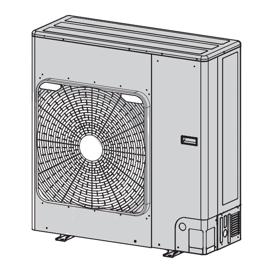
Page 30: Construction Views (External Views)
2. CONSTRUCTION VIEWS (EXTERNAL VIEWS) 2-1. RAV-GP801AT* – 30 –... -
Page 31: Rav-Gp1101At*, Gp1401At
2-2. RAV-GP1101AT*, GP1401AT* – 31 –... -
Page 32: Branch Pipe
2-3. Branch pipe RBC-DTWP101E (Simultaneous Twin) <Joint pipe> Inner diameter Outer diameter Ø C Ø25.4 Inner Inner diameter diameter Ø D Ø D Inner diameter Ø28.6 1 pc. Model Q’ty Gas side 25.4 15.9 RBC-TWP101E Liquid side 12.7 – 32 –... -
Page 33: Outdoor Unit Refrigeranting Cycle Diagram
3. OUTDOOR UNIT REFRIGERANTING CYCLE DIAGRAM GP801 Pulse motor valve TS sensor Fan motor Capillary tube TO sensor Outdoor heat exchanger TL sensor 4-way valve High-pressure switch Automatic restoration TD sensor OFF:4.15Mpa ON :3.2MPa sensor Distributor Strainer Ø12.7 Liquid pipe Ø9.5 Packed valve Accumulator... - Page 34 GP1101/1401 Pulse motor valve TS sensor Fan motor Capillary tube 4-way valve TO sensor Strainer Ø12.7 Outdoor heat exchanger Check joint Cooling : High pressure TL sensor Heating : Low pressure High-pressure switch Automatic restoration TD sensor OFF:4.15Mpa ON :3.2MPa sensor Liquid tank (500cc)
- Page 35 RAV-GP801 series Pressure Pipe surface temperature (˚C) Compressor Indoor/outdoor indoor heat Outdoor heat indoor drive revolution temp.condition (Mpa) (kg/cm g) Discharge suction exchanger exchanger frequency (rps) (TD) (TS) (TC) (TL) (TE) indoor outdoor Standard 27.9 11.0 71.7 15.6 14.0 46.8 43.0 48.0 HIGH...
-
Page 36: Wiring Diagram
4. WIRING DIAGRAM 4-1. RAV-GP801AT* – 36 –... -
Page 37: Rav-Gp1101At*, Gp1401At
4-2. RAV-GP1101AT*, GP1401AT* – 37 –... -
Page 38: Specifications Of Electrical Parts
5. SPECIFICATIONS OF ELECTRICAL PARTS 5-1. Outdoor Unit RAV-GP801AT* Parts name Type Specifications Compressor NX220A1F-20N — Outdoor fan motor ICF-280-A60-1 DC280V, 60W 4-way valve coil STF-H01AZ1724A1 DC12V PMV coil UKV-A040 DC12V High pressure switch ACB-4UB83W OFF:4.15MPa Compressor thermostat US-622 OFF:125 ± 4˚C , ON:90 ± 5˚C Reactor CH-101 10mH, 20A... -
Page 39: Refrigerant R32
6. REFRIGERANT R32 This air conditioner adopts the R32 refrigerant which 7. Be sure to carry out installation or removal does not damage the ozone layer. according to the installation manual. The working pressure of the new refrigerant R32 is Improper installation may cause refrigeration 1.6 times higher than conventional refrigerant (R22). -
Page 40: Processing Of Piping Materials
Table 6-2-1 Thicknesses of annealed copper pipes Thickness (mm) Nominal diameter Outer diameter (mm) R410A or R32 0.80 0.80 0.80 0.80 12.7 0.80 0.80 15.9 1.00 1.00 1. Joints For copper pipes, flare joints or socket joints are used. Prior to use, be sure to remove all contaminants. a) Flare Joints Flare joints used to connect the copper pipes cannot be used for pipings whose outer diameter exceeds 20 mm. - Page 41 c) Insertion of Flare Nut d) Flare Processing ØD Make certain that a clamp bar and copper pipe have been cleaned. By means of the clamp bar, perform the flare processing correctly. Use either a flare tool for R410A / R32 or conventional flare tool.
- Page 42 Fig. 6-2-2 Relations between flare nut and flare seal surface 2. Flare Connecting Procedures and Precautions a) Make sure that the flare and union portions do not have any scar or dust, etc. b) Correctly align the processed flare surface with the union axis. c) Tighten the flare with designated torque by means of a torque wrench.
-
Page 43: Tools
6-3. Tools 6-3-1. Required Tools Refer to the “4. Tools” (Page 14) 6-4. Recharging of Refrigerant When it is necessary to recharge refrigerant, charge the specified amount of new refrigerant according to the following steps. Recover the refrigerant, and check no refrigerant remains in the equipment. -
Page 44: Brazing Of Pipes
1) Be sure to make setting so that liquid can be charged. 2) When using a cylinder equipped with a siphon, liquid can be charged without turning it upside down. R32 refrigerant is a Single-component refrigerant that does not change its composition. Although it is possible to charge the refrigerant with either liquid or gas, charge it with liquid. -
Page 45: Brazing
2. Characteristics required for flux 6-5-3. Brazing • Activated temperature of flux coincides with the As brazing work requires sophisticated techniques, brazing temperature. experiences based upon a theoretical knowledge, it must be performed by a person qualified. • Due to a wide effective temperature range, flux is In order to prevent the oxide film from occurring in the hard to carbonize. -
Page 46: Instructions For Re-Use Piping Of R22 Or R407C
Operation System case. • In the concurrent twin system, when TOSHIBA- ∗ ∗ ∗ ∗ ∗ Pipe diameter and thickness (mm) specified branching pipe is used, it can be reused. -
Page 47: Final Installation Checks
6-6-5. Final Installation Checks Existing pipes: Cannot be used. Are there scratches or dents on the existing pipes? • Use new pipes. Is it possible to operate the existing air conditioner? • After the existing air conditioner is operated in cooling mode for approx. -
Page 48: Handling Of Existing Pipe
6-6-6. Handling of Existing Pipe 6-6-7. Recovering Refrigerant When using the existing pipe, carefully check it for Use the refrigerant recovery equipment to recover the the following: refrigerant. • Wall thickness (within the specified range) 6-7. Charging additional refrigerant • Scratches and dents •... -
Page 49: General Safety Precautions For Using R32 Refrigerant
6-8. General safety precautions for using R32 refrigerant 6-8-1. Recovery 6-8-2. Decommissioning • When removing refrigerant from a system, either for • Before carrying out this procedure, it is essential servicing or decommissioning, it is recommended that the technician is completely familiar with the good practice that all refrigerants are removed equipment and all its details. -
Page 50: Circuit Configuration And Control Specifications
7. CIRCUIT CONFIGURATION AND CONTROL SPECIFICATIONS 7-1. Outdoor Unit Control 7-1-1. Print Circuit Board, MCC-1705 CN807 (WHT) Connector for temperature sensor CN805 (BLU) Connector for TL CN604 (WHT), TD CN603 (WHT), TO CN602 (YEL) Connector for Display P.C. board MCC-1646 TE CN601 (WHT), TS CN600 (WHT) Option P.C. -
Page 51: Outline Of Main Controls
7-2. Outline of Main Controls 1. PMV (Pulse Motor Valve) control 1) The aperture of the PMV is controlled between 30 to 500 pulses during operation. 2) During cooling operations, the PMV aperture is controlled by the temperature difference between TS sensor and TC sensor, the temperature difference in cooling operations is usually controlled using a 1 to 4K target value. - Page 52 3. Outdoor fan revolution number control Control of fan revolution number and the fan taps in this unit are shown below. Fan Taps Revolution number Allocation [rpm] GP80 GP110 Upper Fan GP140 Lower Fan 3-1. Cooling fan control 1) Cooling operations of the outdoor fan are controlled by a TL sensor, TO sensor and the compressor revolution number.
- Page 53 3-2. Heating fan control 1) Heating operations of the outdoor fan are controlled by a TE sensor, TO sensor and the compressor revolution number. (Control from a minimum W1 to a maximum is performed according to the table below). 2) Operation is fixed for 3 minutes after start up by a maximum fan tap corresponding to the zones in the table below.
- Page 54 4. Defrost control 1) During heating operations, defrost operations are performed when the temperature from the TE sensor satisfies any of the conditions in the A to D zones. 2) During defrosting operations, defrost will be terminated if the temperature from the TE sensor continues at 12°C or higher for 3 seconds or if the temperature is 7°C ≤...
- Page 55 7. Heat sink temperature detection control 1) IGBT overheating prevention is protective control performed by a thermistor (TH sensor) in proximity to IGBT. 2) When a temperature of TH e” 90°C is detected, the fan tap is moved by 1 step up. Thereafter step-up is performed at a rate of +1 tap/5 seconds until a maximum fan tap is reached.
- Page 56 12. Coil heating control 1) This control has the function of heating the compressor by applying a current to the compressor when not operating instead using a case heater. This control is for the purpose of preventing stagnation of the refrigerant inside the compressor. 2) Malfunction in the compressor may result if a current is not applied for a specified time before a test run after installation as was previously the case.
-
Page 57: Troubleshooting
8. TROUBLESHOOTING 8-1. Summary of Troubleshooting <Wired remote controller type> 1. Before troubleshooting 1) Required tools/instruments • + and – screwdrivers, spanners, radio cutting pliers, nippers, push pins for reset switch • Tester, thermometer, pressure gauge, etc. 2) Confirmation points before check a) The following operations are normal. - Page 58 <Wireless remote controller type> 1. Before troubleshooting 1) Required tools/instruments • + and – screwdrivers, spanners, radio cutting pliers, nippers, etc. • Tester, thermometer, pressure gauge, etc. 2) Confirmation points before check a) The following operations are normal. 1. Compressor does not operate. •...
-
Page 59: Troubleshooting
8-2. Troubleshooting 8-2-1. Outline of judgment The primary judgment to check whether a trouble occurred in the indoor unit or outdoor unit is carried out with the following method. Method to judge the erroneous position by flashing indication on the display part of the indoor unit (sensors of the receiving part) The indoor unit monitors the operating status of the air conditioner, and the blocked contents of self-diagnosis are displayed restricted to the following cases if a protective circuit works. - Page 60 Lamp indication Check code Cause of trouble occurrence Operation Timer Ready Heat exchanger sensor (TCJ) trouble Heat exchanger sensor (TC) trouble Indoor unit sensor trouble Heat exchanger sensor (TA) trouble Alternate flash Discharge temp. sensor (TD) trouble Temp. sensor (TE) trouble Operation Timer Ready Temp.
-
Page 61: Others (Other Than Check Code)
8-2-2. Others (Other than Check Code) Lamp indication Check code Cause of trouble occurrence Operation Timer Ready — During test run Simultaneous flash Operation Timer Ready Disagreement of cool/heat — (Automatic cool/heat setting to automatic cool/heat prohibited model, or setting of heating to cooling-only model) Alternate flash –... -
Page 62: Monitor Function Of Remote Controller Switch
8-2-3. Monitor Function of Remote Controller Switch Calling of sensor temperature display <Contents> Each data of the remote controller, indoor unit and outdoor unit can be understood by calling the service monitor mode from the remote controller. <Procedure> Push buttons simultaneously for 4 seconds to call the service monitor mode. -
Page 63: Check Code List (Outdoor)
– 63 –... - Page 64 – 64 –...
- Page 65 Failure mode detected by indoor unit Operation of diagnostic function Judgment and measures Check Status of Cause of operation Condition code air conditioner 1. Check cables of remote controller and communication adapters. No communication from remote Displayed when Stop controller (including wireless) and •...
- Page 66 Failure mode detected by outdoor unit Operation of diagnostic function Check code Judgment and measures Status of Cause of operation Condition air conditioner Indoor unit Disconnection, short of discharge Displayed when 1. Check discharge temp. sensor (TD). Stop temp. sensor (TD) trouble is detected 2.
- Page 67 Operation of diagnostic function Check code Judgment and measures Status of Cause of operation Condition air conditioner Indoor unit Discharge temp. trouble 1. Check refrigerating cycle (Gas leak) Displayed when ∗ Discharge temp. (TD) over 2. Trouble of electronic expansion valve Stop trouble is detected specified value was detected.
- Page 68 Failure mode detected by remote controller or central controller (TCC-LINK) Operation of diagnostic function Judgment and measures Status of Check code Cause of operation Condition air conditioner Power supply trouble of remote controller, Indoor EEPROM trouble Not displayed 1. Check remote controller inter-unit wiring. No communication with header indoor unit at all 2.
-
Page 69: Diagnostic Procedure For Each Check Code (Outdoor Unit)
8-2-5. Diagnostic Procedure for Each Check Code (Outdoor Unit) 1) This section describes the diagnostic method for each check code displayed on the wired remote controller. 2) In some cases, a check code indicates multiple symptoms. In this case, confirm LED display on the outdoor P.C. board to narrow the contents to be confirmed. 3) The check code on the remote controller is displayed only when the same trouble occurred continuously by multiple times while LED of the outdoor P.C. - Page 70 Check Outdoor Check and troubleshooting code LED display (Item without special mention Indicates part of outdoor unit.) [F04] [Discharge temp. sensor (TD) trouble] Is connection of CN603 correct? Correct connector. Is resistance value of TD sensor correct? Replace TD sensor Check outdoor P.C.
- Page 71 Check Outdoor Check and troubleshooting code LED display (Item without special mention Indicates part of outdoor unit.) [F15] [Miswiring of heat exchanger sensor (TE, TS)] Is mounting status of Correct sensor mounting. TE and TS sensors correct? Is connection of CN600 correct? Correct connector.
- Page 72 Check Outdoor Check and troubleshooting code LED display (Item without special mention Indicates part of outdoor unit.) [H02] [Compressor lock] Is power supply voltage normal? Correct power supply line. AC198 to 264V Is wire connection correct? Compressor lead Check wire connection (P.C.
- Page 73 Check Outdoor Check and troubleshooting code LED display (Item without special mention Indicates part of outdoor unit.) [L10] [Heat sink temp. sensor (TH) trouble] Cut jumper line according to the explanation sheet packaged with the service P.C. board. [L29] [Communication trouble MCUs] Check outdoor P.C.board Failure →...
- Page 74 Check Outdoor Check and troubleshooting code LED display (Item without special mention Indicates part of outdoor unit.) [P07] [Heat sink overheat trouble] Is there any looseness in the screw stop of the motor drive element Apply radiation grease IC200 of the outdoor P.C. board, to objective, retightening the sub heat sink, and the diode bridge? of screw...
- Page 75 Check Outdoor Check and troubleshooting code LED display (Item without special mention Indicates part of outdoor unit.) [P19] [4-way valve inverse trouble] Does 4-way valve Is the coil work correctly? resistance Replace (Check pipe temp. etc. value of 4-way 4-way valve coil in cooling/heating valve normal? operation.)
- Page 76 Check Outdoor Check and troubleshooting code LED display (Item without special mention Indicates part of outdoor unit.) [P20] [High pressure protective operation] [P04] Is service valve Open service valve fully. fully opened? Reset the power supply and then perform test run Cooling season matching to the season.
- Page 77 Check Outdoor Check and troubleshooting code LED display (Item without special mention Indicates part of outdoor unit.) [P22] [Fan system trouble] Is power supply voltage normal? Check wiring construction. AC198 to 264V Ask repair of power supply. Rotate shaft of the fan motor by hands during power-OFF.
- Page 78 Check Outdoor Check and troubleshooting code LED display (Item without special mention Indicates part of outdoor unit.) [P26] [Short-circuit of compressor drive element] Are connections of compressor lead and reactor correct? Correct wiring. (Check referring to the Wiring diagram.) Does the same trouble occur in Replace outdoor operation without compressor lead? P.C.
- Page 79 Temperature sensor Temperature – Resistance value characteristic table TA, TC, TCJ, TE, TS, TO sensors TD, TL sensors Representative value Representative value Resistance value (k Ω) Resistance value (k Ω) Temperature Temperature (˚C) (˚C) (Minimum value) (Standard value) (Maximum value) (Minimum value) (Standard value) (Maximum value) 32.33 33.80...
-
Page 80: Setup At Local Site And Others
9. SETUP AT LOCAL SITE AND OTHERS 9-1. Calling of Check code History <Contents> The trouble contents in the past can be called. <Procedure> TEMP. ON / OFF Push buttons simultaneously for 4 seconds or TIMER SET MODE more to call the service check mode. TIME SAVE VENT... - Page 81 Indoor unit power-ON sequence Power ON • The unit without power feed waits entirely → Waiting status is released by system start • Reboot when power is fed on the way <By feed unit> <Automatic address judgment> Not normal 3 minutes elapse Gr construction check Normal ∗...
-
Page 82: Outdoor Unit
9-2. Outdoor Unit Various status displays and operations can be accessed using the push buttons (service switches) on the outdoor Control P.C. board and LED display. Service switch (SW01 and SW02) operation <GP110, GP140> SW01 SW02 (D800 to D805) <GP80> SW01 SW02 (D800 to D805) - Page 83 1. Various settings available via the outdoor unit (Existing pipe, Maximum frequency change, Snow guard fan control, Cooling only setup, etc.) (1) Service switch setting Various settings can be made using the service switches [Method of operation] 1) Ensure the LED display shows the initial status. If not then ensure to restore the initial status. 2) Press SW01 for at least 5 seconds.
- Page 84 Various settings confirmation method Whether the various settings are in effect or not can be confirmed. 1) Ensure the LED display shows the initial status. If not then ensure to restore the initial status. 2) Push SW01 for at least 5 seconds. D804 will start slowly flashing. 3) Push SW01 several times until reaching the desired function on the LED display.
- Page 85 2. Service support functions (LED display and switch operation) (1) LED display switching (SW01 and SW02 operation) (1)-1. Display switch list Service switches SW01 and SW02 can be used to change the display content of LEDs D800 to D805 on the outdoor unit.
- Page 86 (1)-2. Trouble display Current and the latest trouble (latest and including the present trouble) can be checked using the lighting status of the LEDs D800 to D805 on the outdoor unit. (1)-2-1. Current trouble indication LED indication Wired remote Name of trouble control trouble code D800 D801 D802 D803 D804 D805 Normal...
- Page 87 (1)-3. Sensor, current, compressor operation frequency, PMV opening indication Interface (CDB) P.C. board detected values (for example temperature and current sensor values) can be easily checked. ∗ Temperature sensors ... TD, TE, TL, TS, TO, TH, TA, TC, TCJ ∗ Current ......Current sensor (CT) value detected LED indication Temperature Compressor...
- Page 88 (1)-4. Refrigerant leak detection function Monitors the amount of refrigerant being circulated based on the temperature sensors, compressor rotation speed, PMV opening during operation, and detects any refrigerant leaks during operation and indicates it using the LEDs on the outdoor unit. CAUTION ∗...
- Page 89 (2) Maintenance inspections Special operations (SW01 and SW02 operations) The following special maintenance and inspection operations can be carried out using the service switches SW01 and SW02. [Method of operation] 1) Ensure the LED display shows the initial state. If not then please ensure to return it to the initial state. 2) Push and hold down SW01 for at least 5 seconds.
- Page 90 3. Outdoor application operation Optional connector kit (TCB-PCOS1E2) (1) Peak-cut control • Saves the power of the outdoor unit by the external peak-cut signal to suppress temporary peak power dissipation. • The power saving can be switched to three levels: 75%, 50%, and operation stop. (2) Night operation •...
-
Page 91: Address Setup
10. ADDRESS SETUP 10-1. Address Setup Procedure When an outdoor unit and an indoor unit are connected, or when an outdoor unit is connected to each indoor unit respectively in the group operation even if multiple refrigerant lines are provided, the automatic address setup completes with power-ON of the outdoor unit. -
Page 92: Address Setup & Group Control
10-2. Address Setup & Group Control <Definitions of terms> Indoor unit No. : N - n = Outdoor unit line address N (Max. 30) - Indoor unit address n (Max. 64) Group address : 0 = Single (Not group control) 1 = Master unit in group control 2 = Sub unit in group control Master unit (= 1) : The representative of multiple indoor units in group operation sends/receives signals to/... -
Page 93: System Configuration
10-2-1. System Configuration 1. Single Outdoor Indoor (Master/Header) Individual Remote controller 2. Twin Master/Header Sub/Follower 3. Single group operation Sub/Header Sub/Header Sub/Header Master/Header Sub/Header (Max. : 8 units) • Each interior unit controls the outdoor unit individually. 4. Multiple groups operation (Single, Twin operation) Sub/Header Sub/Header Sub/Follower... -
Page 94: Automatic Address Example From Unset Address (No Miswiring)
10-2-2. Automatic Address Example from Unset Address (No miswiring) 1. Standard (One outdoor unit) 1. Single 2. Twin Individual Master/Header Sub/Follower Only turning on source power supply (Automatic completion) 2. Single group operation (Multiple outdoor units = Multiple indoor units only with serial communication) Sub/Header Sub/Header Sub/Header... -
Page 95: Address Setup (Manual Setting From Remote Controller)
10-4. Address Setup (Manual setting from remote controller) (Example of 2-lines wiring) In case that addresses of the indoor units will be (Real line: Wiring, Broken line: Refrigerant pipe) determined prior to piping work after wiring work Outdoor Outdoor • Set an indoor unit per a remote controller. 1 2 3 1 2 3 •... -
Page 96: Confirmation Of Indoor Unit No. Position
10-5. Confirmation of Indoor Unit No. Position 1. To know the indoor unit addresses though position of the indoor unit body is recognized • In case of individual operation (Wired remote controller : indoor unit = 1 : 1) (Follow to the procedure during operation) <Procedure>... - Page 97 <Maintenance/Check list> Aiming in environmental preservation, it is strictly recommended to clean and maintain the indoor/outdoor units of the operating air conditioning system regularly to secure effective operation of the air conditioner. It is also recommended to maintain the units once a year regularly when operating the air conditioner for a long time.
-
Page 98: Replacement Of The Service P.c. Board
11. REPLACEMENT OF THE SERVICE P.C. BOARD 1. DN setting the jumper wires and DIP switches Part name Function Setting Jumper J800 ~ J804 Model switching Cut these jumper wires according to the wire following table. J805 ~ J807 Settings Set these jumper wires same as the settings of the P.C. -
Page 99: How To Exchange Compressor
12. HOW TO EXCHANGE COMPRESSOR 12-1. Exchanging Procedure of Compressor (Outline) START Open PMV forcedly and then recover refrigerant Has refrigerant recovery work been done? using a refrigerant recovery unit. Turn off the circuit breaker. Never recover the refrigerant to the outdoor unit. •... -
Page 100: Detachments
13. DETACHMENTS 13-1. RAV-GP801AT* No. Part name Procedure Remarks WARNING Common Front panel procedures Stop operation of the air conditioner and turn off breaker Front panel switch. Top cover CAUTION Ensure wearing of gloves when performing any work in order to avoid injury from parts, etc. Left cl Left claw Left claw... - Page 101 No. Part name Procedure Remarks Side 1. Detachment Side cabinet (left) cabinet 1) Following to work of Detachment of (left) 2) Remove the side cabinet (left) and base plate screws. (2 pcs, Ø4 ×10 hexagon screws) 3) Slide the side cabinet (left) downwards and remove. 2.
- Page 102 No. Part name Procedure Remarks Electrical 1. Detachment (Control P.C. board) part 1) Following to work of Detachment of (Control P.C. board ) WARNING Do not disassemble the inverter for a minute after the power is turned off since there is a risk of electric shock. *1.Ensure to bundle again with a commercially available Inverter cover Inverter cover...
- Page 103 No. Part name Procedure Remarks Electrical 14) Remove the heat sink duct and inverter box fixing Inverter box Inverter box Inverter box part screw (Continued) (ST3T Ø4×8, 2 pcs) Heat sink duct and Heat sink duct and Heat sink duct and Inverter box fixing Inverter box fixing Inverter box fixing...
- Page 104 No. Part name Procedure Remarks Electric 3. Detachment (Reactor) part 1) Following to work of Detachment of Reactor (Reactor) 2) Remove the connector of the reactor lead wire connected to the reactor. (2 positions) 3) Remove the connector. Reactor lead × 2 ( Ø4 ST3T, 2 pcs,) 4.
- Page 105 No. Part name Procedure Remarks Fan motor 8) Cut the binding band for the air duct fixing fan motor (continued) and the motor base ( 2 position ). 9) Loosen the two claws on the motor base. 10) Remove the fixing screws (4 positions) while holding the fan motor so as not to fall it.
- Page 106 No. Part name Procedure Remarks Compressor WARNING When removing the welding part of the suction / discharge compressor pipe of the compressor, if recovery is insufficient after lead recovering the refrigerant in a well-ventilated place, the refrigerant and refrigerating machine oil may blow, cause injury.
- Page 107 No. Part name Procedure Remarks Compressor 2. Attachment Compressor lead connector Compressor lead connector Compressor lead connector 1) Attach the compressor in the reverse process of compressor “1. Detachment”. lead Ferrite core Ferrite core Ferrite core (continued) Roll the compressor lead Roll the compressor lead Roll the compressor lead •...
- Page 108 No. Part name Procedure Remarks PMV coil 1. Detachment Bundle the all lead wires on the back face and then cut the 1) Following to work of Detachment of binding band fixing inverter box. 2) Cut the binding band (two positions) on the back surface 3) Pull the connector for PMV coil out of control P.C.
- Page 109 No. Part name Procedure Remarks Fan guard 1. Detachment 1) Following to work of Detachment of Discharge cabinet NOTE Do the work on cardboard or a cloth etc. spread out to prevent the product from being scratched. Hooking claw Hooking claw Hooking claw 2) Remove the outlet cabinet and place the fan guard side facing down.
-
Page 110: Rav-Gp1101At*, Gp1401At
13-2. RAV-GP1101AT*, GP1401AT* No. Part name Procedure Remarks Common WARNING Front panel procedures Stop operation of the air conditioner and turn off breaker switch. Front panel Top cover CAUTION Ensure wearing of gloves when performing any work in order to avoid injury from parts, etc. Right claw Right claw Right claw... - Page 111 No. Part name Procedure Remarks Side 1. Detachment cabinet Side cabinet (left) 1) Following to work of Detachment of (left) 2) Remove the side cabinet (left) and base plate screws. (2 pcs, Ø4 ×10 hexagon screws) 3) Slide the side cabinet (left) downwards and remove. 2.
- Page 112 No. Part name Procedure Remarks 1. Detachment (Control P.C. board) Electrical part 1) Following to work of Detachment of (Control P.C. board ) WARNING Do not disassemble the inverter for a minute after the power is turned off since there is a risk of electric shock. *1.Ensure to bundle again with a commercially available code clamp Inverter cover...
- Page 113 No. Part name Procedure Remarks Electrical 14) Remove the heat sink duct and inverter box fixing Inverter box Inverter box Inverter box part screw (Continued) (ST3T Ø4×8, 2 pcs) Heat sink duct and Heat sink duct and Heat sink duct and Inverter box fixing Inverter box fixing Inverter box fixing...
- Page 114 No. Part name Procedure Remarks Electric 3. Detachment (Reactor) part 1) Following to work of Detachment of Reactor (Reactor) 2) Remove the connector of the reactor lead wire connected to the reactor. (2 positions) 3) Remove the connector. Reactor lead × 2 ( Ø4 ST3T, 2 pcs,) 4.
- Page 115 No. Part name Procedure Remarks Fan motor 8) Cut the binding band for the air duct fixing fan motor Binding band (Continued) and the motor base ( 2 position ). Claw For upper fan motor: one at the motor base For lower fan motor: one at the motor base one at the air duct Loose the claw on the fan motor base (2 positions)
- Page 116 No. Part name Procedure Remarks Compressor WARNING When removing the welding part of the suction / discharge compressor pipe of the compressor, remove them after recovering the lead refrigerant in a well-ventilated place. if recovery is insufficient the refrigerant and refrigerating machine oil may squirt, cause injury.
- Page 117 No. Part name Procedure Remarks Compressor 2. Attachment Compressor lead connector Compressor lead connector Compressor lead connector 1) Attach the compressor in the reverse process of “1. compressor Detachment”. lead Ferrite core Ferrite core Ferrite core (Continued) Roll the compressor lead Roll the compressor lead Roll the compressor lead •...
- Page 118 No. Part name Procedure Remarks PMV coil 1. Detachment Bundle the all lead wires on 1) Following to work of Detachment of the back face and then cut the binding band fixing inverter box. 2) Cut the binding band (2 positions) on the back surface Cut the binding Cut the binding Cut the binding...
- Page 119 No. Part name Procedure Remarks Fan guard 1. Detachment 1) Following to work of Detachment of NOTE Discharge cabinet Do the work on cardboard or a cloth etc. spread out to prevent the product from being scratched. 2) Remove the outlet cabinet and place the fan guard Hooking claw Hooking claw Hooking claw...
-
Page 120: Exploded Views And Parts List
14. EXPLODED VIEWS AND PARTS LIST 14-1. Outdoor Unit RAV-GP801AT(J)-E, RAV-GP801AT-TR 012, 013 029, 030 033, 034 031, 032 016, 017 037, 038 019, 020, 021 022, 023, 024 035, 036 – 120 –... - Page 121 PANEL, SIDE 4310A165 PANEL, SIDE, LEFT 43100437 PANEL, FRONT, PIPING 4310A115 PANEL, BACK, PIPING 43107276 HANGER 43107295 HADLE, HANGER 4311M659 MARK, TOSHIBA 43122153 SUPPORTER, MOTOR 43122154 SUPPORTER, MOTOR 4312C042 MOTOR, FAN, ICF-280-A60-1 43120270 FAN, PROPELLER, PS561 43F47669 NUT, FLANGE 43197164...
- Page 122 RAV-GP1101AT(J)-E, RAV-GP1401AT(J)-E RAV-GP1101AT-TR, RAV-GP1401AT-TR 027, 028 031, 032 015, 016 029, 030 036, 037 018, 019, 020 021, 022, 023 034, 035 – 122 –...
- Page 123 PANEL, SIDE 4310A127 PANEL, SIDE, LEFT 43100437 PANEL, FRONT, PIPING 4310A115 PANEL, BACK, PIPING 43107276 HANGER 43107295 HADLE, HANGER 4311M659 MARK, TOSHIBA 43122177 SUPPORTER, MOTOR 4312C100 MOTOR, FAN, ICF-280-A100-1(A) 43120270 FAN, PROPELLER, PS561 43F47669 NUT, FLANGE 43197164 NUT, FLANGE 43141529...
-
Page 124: Inverter Assembly
14-2. Inverter Assembly SPACER, COLLAR SPACER, BUSH PC BOARD ASSY, MCC-1705 PC BOARD ASSY, MCC-1646 FUSE(10A) SENSOR, TD HOLDER, SENSOR(TO) SENSOR, TL SENSOR, TE HOLDER, SENSOR(TD) SENSOR, TO HOLDER, SENSOR(TS) SENSOR, TS HOLDER, SENSOR(TE) TERMINAL BLACK,3P 20A TERMINAL BLACK,3P 60A Q’ty/Set RAV-GP 1101AT-E... - Page 125 TOSHIBA CARRIER CORPORATION 72-34 Horikawa-cho, Saiwai-ku, Kawasaki-shi, Kanagawa 212-8585, JAPAN Copyright © 2018 TOSHIBA CARRIER CORPORATION, ALL Rights Reserved.
Need help?
Do you have a question about the RAV-GM 801UT-E and is the answer not in the manual?
Questions and answers