Table of Contents
Advertisement
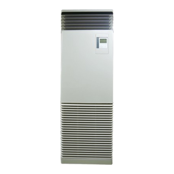
SERVICE MANUAL
AIR-CONDITIONER (SPLIT TYPE)
INDOOR UNIT
<Floor Standing Type>
RAV-RM561FT-EN/ES
RAV-RM801FT-EN/ES
RAV-RM1101FT-EN/ES
RAV-RM1401FT-EN/ES
RAV-RM1601FT-EN/ES
RAV-RM561FT-TR
RAV-RM801FT-TR
RAV-RM1101FT-TR
RAV-RM1401FT-TR
RAV-RM1601FT-TR
FILE NO. A10-1906
PRINTED IN JAPAN, Aug., 2019
ToMo
Advertisement
Table of Contents
Troubleshooting

Related Manuals for Toshiba RAV-RM561FT-EN


Summary of Contents for Toshiba RAV-RM561FT-EN
- Page 1 FILE NO. A10-1906 SERVICE MANUAL AIR-CONDITIONER (SPLIT TYPE) INDOOR UNIT <Floor Standing Type> RAV-RM561FT-EN/ES RAV-RM801FT-EN/ES RAV-RM1101FT-EN/ES RAV-RM1401FT-EN/ES RAV-RM1601FT-EN/ES RAV-RM561FT-TR RAV-RM801FT-TR RAV-RM1101FT-TR RAV-RM1401FT-TR RAV-RM1601FT-TR PRINTED IN JAPAN, Aug., 2019 ToMo...
-
Page 2: Table Of Contents
CONTENTS PRECAUTION FOR SAFETY ..................6 ABOUT REFRIGERANT R32 ..................16 ABOUT REFRIGERANT R410A ................19 1. CONSTRUCTION VIEWS (EXTERNAL VIEWS) ............ 21 1-1. RAV-RM561FT* ........................21 1-2. RAV-RM801FT* ........................22 1-3. RAV-RM1101FT*, RM1401FT*, RM1601FT* ............... 23 2. WIRING DIAGRAMS ....................24 3. - Page 3 • The qualified service person is a person who installs, repairs, maintains, relocates and removes the air conditioners made by Toshiba Carrier Corporation. He or she has been trained to install, repair, maintain, relocate and remove the air conditioners made by Toshiba Carrier Corporation...
- Page 4 Definition of Protective Gear When the air conditioner is to be transported, installed, maintained, repaired or removed, wear protective gloves and ‘safety’ work clothing. In addition to such normal protective gear, wear the protective gear described below when undertaking the special work detailed in the table below.
- Page 5 Warning Indications on the Air Conditioner Unit [Confirmation of warning label on the main unit] Confirm that labels are indicated on the specified positions. If removing the label during parts replace, stick it as the original. WARNING WARNING ELECTRICAL SHOCK HAZARD ELECTRICAL SHOCK HAZARD Disconnect all remote Disconnect all remote electric power supplies before servicing.
-
Page 6: Precaution For Safety
Precaution for Safety The appliance shall be installed in accordance with national wiring regulations. Capacity shortages of the power circuit or an incomplete installation may cause an electric shock or fire. DANGER Before carrying out the installation, maintenance, repair or removal work, be sure to set the circuit breaker to the OFF position. - Page 7 WARNING Before starting to repair the air conditioner, read carefully through the Service Manual, and repair the air conditioner by following its instructions. ∗ Only qualified service person ( 1) is allowed to repair the air conditioner. Repair of the air conditioner by unqualified person may give rise to a fire, electric shocks, injury, water leaks and/or other problems.
- Page 8 If, in the course of carrying out repairs, it becomes absolutely necessary to check out the electrical parts with the electrical parts box cover of one or more of the indoor units and the service panel of the outdoor unit removed in order to find out exactly where the trouble lies, wear insulated heat-resistant gloves, insulated boots and insulated work overalls, and take care to avoid touching any live parts.
- Page 9 This Air Conditioner has adopted a refrigerant HFC R32 or R410A. Be sure to check the refrigerant type for outdoor unit to be combined. In case that refrigerant type is R32, this unit uses a mildly flammable refrigerant. If refrigerant leaks and comes in contact with fire or heating part, it will create harmful gas and there is risk of fire.
- Page 10 After repair work, surely assemble the disassembled parts, and connect and lead the removed wires as before. Perform the work so that the cabinet or panel does not catch the inner wires. If incorrect assembly or incorrect wire connection was done, a disaster such as a leak or fire is caused at user fs side.
- Page 11 When the service panel of the outdoor unit is to be opened in order for the compressor or the area around this part to be repaired immediately after the air conditioner has been shut down, set the circuit breaker to the OFF position, and then wait at least 10 minutes before opening the service panel.
- Page 12 CAUTION Ensure wearing of gloves when performing any work in order to avoid injury from parts, etc. Failure to wear the proper protective gloves cause an injury due to the parts, etc. Wearing of gloves When performing the brazing work, check whether refrigerant leaks or remains. If the leakage refrigerant gas touches a fire source, it may generate noxious gases, causing a fire.
- Page 13 APPENDIX Minimum floor area: Amin (m When an outdoor unit using R32 refrigerant is combined with this indoor unit, do not install the indoor unit in a poorly ventilated space that is smaller than the minimum floor area (Amin). For refrigerant quantity, refer to Fluorinated Greenhouse Gases label on the outdoor unit. For the minimum floor area (Amin) of this indoor unit, refer to table below.
- Page 14 Declaration of Conformity Manufacturer: TOSHIBA CARRIER CORPORATION 336 Tadehara, Fuji-shi, Shizuoka-ken 416-8521 JAPAN TCF holder: TOSHIBA CARRIER EUROPE S.A.S Route de Thil 01120 Montluel FRANCE Hereby declares that the machinery described below: Generic Denomination: Air Conditioner Model / type: Indoor unit...
- Page 15 Specifications Sound pressure level (dB(A)) Model Weight (kg) Cooling Heating ∗ ∗ RAV-RM561FT-EN/ES ∗ ∗ RAV-RM801FT-EN/ES ∗ ∗ RAV-RM1101FT-EN/ES ∗ ∗ RAV-RM1401FT-EN/ES ∗ ∗ RAV-RM1601FT-EN/ES ∗ ∗ RAV-RM561FT-TR ∗ ∗ RAV-RM801FT-TR ∗ ∗ RAV-RM1101FT-TR ∗ ∗ RAV-RM1401FT-TR ∗ ∗ RAV-RM1601FT-TR ∗...
-
Page 16: About Refrigerant R32
About refrigerant R32 This air conditioner adopts a new HFC type refrigerant (R32) which does not deplete the ozone layer. 1. Safety Caution Concerned to Refrigerant R32 Be sure that water, dust, the former refrigerant or the former refrigerating oil is not mixed into the refrigerating cycle of the air conditioner with refrigerant R32 during installation work or service work. - Page 17 <Caution items> 1) The opposite side dimension of the air-conditioner’s flared nut using R32 and the shape of the charge port are the same as those of R410A. 2) Be careful not to charge refrigerant by mistake. Should the different type of refrigerant be mixed, be sure to recharge the refrigerant.
- Page 18 4. Tools : R410A tools available : Partly unavailable, : R410A tools unavailable Installation/service tools Applicability to R32 air Applicability to R22 air conditioner or not conditioner or not Tools / Equipment specification 1 Flare tool Clutch type Pipe flaring Copper pipe gauge for Flaring by adjusting projection...
-
Page 19: About Refrigerant R410A
About refrigerant R410A This air conditioner adopts a HFC type refrigerant (R410A) which does not deplete the ozone layer. 1. Safety Caution Concerned to R410A Refrigerant The pressure of R410A is 1.6 times higher than that of the former refrigerant (R22). Accompanied with change of refrigerant, the refrigerating oil has been also changed. - Page 20 4. Tools 1. Required Tools for R410A Mixing of different types of oil may cause a trouble such as generation of sludge, clogging of capillary, etc. Accordingly, the tools to be used are classified into the following three types. 1) Tools exclusive for R410A (Those which cannot be used for conventional refrigerant (R22)) 2) Tools exclusive for R410A, but can be also used for conventional refrigerant (R22) 3) Tools commonly used for R410A and for conventional refrigerant (R22) The table below shows the tools exclusive for R410A and their interchangeability.
-
Page 21: Construction Views (External Views)
1. CONSTRUCTION VIEWS (EXTERNAL VIEWS) 1-1. RAV-RM561FT* – 21 –... -
Page 22: Rav-Rm801Ft
1-2. RAV-RM801FT* – 22 –... -
Page 23: Rav-Rm1101Ft*, Rm1401Ft*, Rm1601Ft
1-3. RAV-RM1101FT*, RM1401FT*, RM1601FT* – 23 –... -
Page 24: Wiring Diagrams
2. WIRING DIAGRAMS – 24 –... -
Page 25: Parts Rating
3. PARTS RATING Indoor unit Model RAV- RM56∗ RM80∗ RM110∗ RM140∗ RM160∗ Fan motor ICF-340D62-1 ICF-340WD109-1 Louver motor MP24Z4N TA sensor Lead wire length: 1200 mm TC sensor Lead wire length: 1200 mm Vinyl tube (Black) TCJ sensor Lead wire length: 1200 mm Vinyl tube (Red) Refrigerant leak FIS5084-T1C1 detection sensor... -
Page 26: Systematic Refrigerating Cycle Diagram
4. SYSTEMATIC REFRIGERATING CYCLE DIAGRAM 4-1. Indoor Unit • Single type (Combination of 1 indoor unit and 1 outdoor unit) (Indoor unit) Distributor (Strainer incorporated) TCJ sensor Heat exchanger TC sensor Heating Cooling Liquid side Gas side (Outer DIA : A) (Outer DIA : B) To outdoor unit To outdoor unit... - Page 27 Triple type (3 indoor units and 1 outdoor unit) Heating Cooling (Indoor unit A) (Indoor unit B) (Indoor unit C) TCJ sensor TCJ sensor TCJ sensor Distributor Distributor Distributor (with strainer) (with strainer) (with strainer) Heat Heat Heat exchanger exchanger exchanger TC sensor TC sensor...
- Page 28 Double-twin type (4 indoor units and 1 outdoor unit) Heating Cooling (Indoor unit A) (Indoor unit B) TCJ sensor TCJ sensor Distributor Distributor (with strainer) (with strainer) Heat exchanger Heat exchanger TC sensor TC sensor Liquid-side Gas-side Liquid-side Gas-side (Outer DIA : A) (Outer DIA : B) (Outer DIA : A) (Outer DIA : B)
-
Page 29: Indoor Control Circuit
5. INDOOR CONTROL CIRCUIT 5-1. Indoor Controller Block Diagram 5-1-1. Connection of Wired Remote Controller Wired remote controller (Max. 2 units) Display LCD Function setup Display LED Key switch DC5V Remote controller Power circuit communication circuit Indoor unit #1 (Header) Up to 8 units (Follower) (Follower) -
Page 30: Connection Of Wireless Remote Controller Kit
5-1-2. Connection of Wireless Remote Controller Kit – 30 –... -
Page 31: Connection Of Both Wired Remote Controller And Wireless Remote Controller Kit
5-1-3. Connection of Both Wired Remote Controller and Wireless Remote Controller Kit – 31 –... -
Page 32: Control Specifications
5-2. Control Specifications Item Outline of specifications Remarks When power 1) Distinction of outdoor unit supply is reset When the power supply is reset, the outdoors are distin- guished and the control is selected according to the distinguished result. 2) Resetting of indoor fan speed and louver control Fan speed (rpm)/ Based on EEPROM data, select setting of the indoor Air direction adjustment... - Page 33 Item Outline of specifications Remarks Room temp. 2) Using the "Code(DN)" [0006], the setup temperature in Shift of suction control heating operation can be corrected. temperature in heating (Continued) operation Setup "Data" 0000 0002 0004 0006 Setup temp. correction +0˚C +2˚C +4˚C +6˚C...
- Page 34 Item Outline of specifications Remarks Fan speed 1) Operation with (HH), (H+), (H), (L+) (L) or [AUTO] mode HH > H+ > H > L+ > selection L > UL is carried out by the command from the remote controller. 2) When the fan speed mode [AUTO] is selected, the fan speed varies by the difference between TA and Ts.
- Page 35 Item Outline of specifications Remarks Fan speed Number of rotations (rpm) selection RM140 RM56 RM80 RM110 (Continued): RM160 COOL HEAT 3) In heating operation, the mode changes to [UL] if thermostat is turned off. 4) If TA ≥ 25˚C when heating operation has started and when defrost operation has been cleared, the air conditioner operates with [H] mode or higher mode for 1 minute after TC entered in E zone of cool air discharge preventive control...
- Page 36 Item Outline of specifications Remarks Cool air discharge 1) In heating operation, the indoor fan is controlled In D and E zones, the preventive control based on the detected temperature of TC sensor or priority is given to fan TCJ sensor. As shown below, the upper limit of the speed selection setup revolution frequency is restricted.
- Page 37 Item Outline of specifications Remarks High-temp. 1) The heating operation is performed as follows based on the release control detected temperature of TC sensor or TCJ sensor. • When [M] zone is detected, the commanded frequency is However this control is decreased from the real operation frequency.
- Page 38 Item Outline of specifications Remarks Test run Refer to "8-1-1. Test Run Setup on Remote Controller" Frequency in operation depends on connected outdoor units. Filter sign display 1) The indoor fan's cumulative hours of operation are counted, (Except wireless and when these exceed the specified hours (150H), a check type) icon is displayed on LCD of remote controller built in the unit.
- Page 39 Item Outline of specifications Remarks Saving operation 1) When the "Saving operation" is selected during AUTO mode or Cooling or Heating operation, "Saving operation" will be carried out. 2) The setup temperature is shifted (corrected) in the range not to lose the comfort ability according to input values of various sensors.
- Page 40 Item Outline of specifications Remarks Energy saving Perform the power saving operation of the air conditioner. operation Cooling / heating performance may be reduced a little because its power is saved during the Energy saving operation. 1) Push the [ MENU] button.
- Page 41 Item Outline of specifications Remarks Refrigerant Refrigerant detection sensor control This refrigerant leak 1) The R32 refrigerant leak detection control functions according detection sensor detection sensor to refrigerant leak detection sensor mounted in the indoor unit control does not control when outdoor unit using R32 refrigerant is connected to function when an indoor unit.
- Page 42 Item Outline of specifications Remarks 8˚C heating/ 1) Pre-heating operation can be set for cold regions where room Frost protective temperature drops to below zero. operation In a group 2) This function is valid only for combination with the outdoor connection, if there is units.
-
Page 43: Indoor Print Circuit Board
5-3. Indoor Print Circuit Board <MCC-1643> – 43 –... -
Page 44: Optional Connector Specifications Of Indoor P.c. Board
5-4. Optional connector specifications of indoor P.C. board – 44 –... -
Page 45: Troubleshooting
6. TROUBLESHOOTING 6-1. Summary of Troubleshooting <Wired controller type> 1. Before troubleshooting 1) Required tools/instruments • + and – screwdrivers, spanners, long-nose pliers, nippers, push pins for reset switch • Tester, thermometer, pressure gauge, etc. 2) Confirmation points before check a) The following operations are normal. - Page 46 <Wireless remote controller type> 1. Before troubleshooting 1) Required tools/instruments • + and – screwdrivers, spanners, long-nose pliers, nippers, etc. • Tester, thermometer, pressure gauge, etc. 2) Confirmation points before check a) The following operations are normal. 1. Compressor does not operate. •...
-
Page 47: Troubleshooting
6-2. Troubleshooting 6-2-1. Outline of judgment The primary judgment to check whether a trouble occurred in the indoor unit or outdoor unit is carried out with the following method. Method to judge the troubled position by flashing indication on the display part of the indoor unit (sensors of the receiving part) The indoor unit monitors the operating status of the air conditioner, and the blocked contents of self-diagnosis are displayed restricted to the following cases if a protective circuit works. - Page 48 Lamp indication Check code Cause of trouble occurrence Operation Timer Ready Heat exchanger sensor (TCJ) trouble Heat exchanger sensor (TC) trouble Indoor unit sensor trouble Alternate flash Room temperature sensor (TA) trouble Discharge temp. sensor (TD) trouble Temp. sensor (TE) trouble Operation Timer Ready Temp.
-
Page 49: Others (Other Than Check Code)
6-2-2. Others (Other than Check Code) Lamp indication Check code Cause of trouble occurrence Operation Timer Ready — During test run Simultaneous flash Operation Timer Ready Disagreement of cool/heat — (Automatic cool/heat setting to automatic cool/heat prohibited model, or setting of heating to cooling-only model) Alternate flash –... - Page 50 2. Troubleshooting procedure on the check display of remote controller Confirmation and check Check code When a trouble has occurred in the air conditioner, the Code : P10 Unit : 2–2 check code and the unit number of the indoor unit appear Unit number of the on the display of the remote controller.
-
Page 51: Check Code List (Indoor)
– 51 –... - Page 52 Trouble mode detected by indoor unit Operation of diagnostic function Judgment and measures Check Status of Cause of operation Condition code air conditioner 1. Check wires of remote controller and communication adapters. No communication from remote Displayed when Stop controller (including wireless) and trouble is •...
- Page 53 Trouble mode detected by remote controller or central controller (TCC-LINK) Operation of diagnostic function Judgment and measures Status of Check code Cause of operation Condition air conditioner Power supply trouble of remote controller, Indoor EEPROM trouble 1. Check remote controller inter-unit wiring. No communication with header indoor unit 2.
-
Page 54: Diagnostic Procedure For Each Check Code (Indoor Unit)
6-2-4. Diagnostic Procedure for Each Check Code (Indoor Unit) Check code [E01 trouble] Correct inter-unit wires Is inter-unit wires of A and B normal? of remote controller Is the connector on the Correct connection of connector. harness or the harness from terminal block of Check circuit wiring. - Page 55 [E04 trouble] Is group address setup of Does outdoor operate? Check "Code(DN)" [0014]. remote controller correct? Are wiring in indoor unit and Correct wiring and 1, 2, 3 inter-unit wires correct? inter-unit wires. Correct wiring of connector Are wirings of terminal blocks and terminal blocks.
- Page 56 [E11 trouble] Option parts : Application control kit (TCB-PCUC2E) connection of option parts connector Repair of connector (CN1 Red) and indoor connection. P.C. board connector (CN521 Red) normal? Is Red LED (LD1) Replace Application control kit. of the option parts (TCB-PCUC2E) lighting? Red LED (LD1)
- Page 57 [E18 trouble] Correct inter-unit wires Is the A-B connecting wire of of remote controller. a remote control normal? Is the connector on the harness Correct connection of connector. or the harness from terminal block Check circuit wiring. of indoor unit connected correctly? Is group control operation? Check power connection status of indoor unit...
- Page 58 [J29 trouble] Is the connector of refrigerant leak detection Correct connector sensor connected correctly? connection (Indoor P.C board CN214 or the sensor side) Is the refrigerant Replace the refrigerant leak detection sensor leak detection sensor. normal? * * Replace the refrigerant leak detection sensor if it cannot be decided by its appearance.
- Page 59 [J30 trouble] Check that there Are gas is no evidence of Stop using the sprays and No refrigerant leak equipment or sprays ventilate a room. refrigerant leak by using containing flammable gas refrigerant leak (Possibility of miss-detection) • Use a detector to check being used near detector.
- Page 60 [L20 trouble] Network adapter : "1 : 1 Model" Connection Interface (TCB-PCNT30TLE2) Are wiring connections to communication lines U3 and U4 Correct wiring connection. of network adapter normal? Check central controller Is the multiple same central (including network adapter) and control system addresses connected? indoor P.C.
- Page 61 [P10 trouble] Is a short-circuit connector connected to the float Connect the short-circuit connector to the connector. switch connector? (Indoor control board CN34) Replace indoor P.C. board (MCC-1643) [F10 trouble] Is connection of TA sensor connector Correct connection of connector. (CN104 on indoor P.C.
- Page 62 [P12 trouble] Power off. Is the connector Repair the connector CN210 of indoor unit connection. P.C. board connected correctly? Is F01 of the No (Blowout of F01) Replace the indoor P.C. indoor P.C. board (MCC-1643). board normal? Is R04 or R05 No (Blowout of R04 or R05) Replace the indoor P.C.
- Page 63 [P19 trouble] Is operation of 4-way valve normal? Are 1.3 to 1.6kΩ applied to (Check the pipe temp., etc. Replace 4-way valve coil. resistance value of 4-way valve coil ? during cooling/heating operation.) Malfunction Check outdoor P.C. board operation. Check outdoor P.C. board. (See the service manual of a Malfunction →...
- Page 64 [C06 trouble] (“1:1 model” connection interface (TCB-PCNT30TLE2)) n i l n i l ∗1 Correct connection of connector. Is connection of connector normal? ∗1 TCC-LINK connection : CN51 of “1:1 model” connection interface (TCC-LINK adapter) P.C. board (MCC-1440) and CN50 of indoor P.C. board Check connection of A and B terminal blocks.
- Page 65 [E03 trouble] (Header indoor unit) [E03 trouble] is detected when the indoor unit cannot receive a signal from the remote controller (also central controller). Check A and B remote controllers and communication lines of the central control system U3 and U4. As communication is impossible, this check code [E03] is not displayed on the remote controller and the central controller.
- Page 66 Temperature sensor Temperature – Resistance value characteristic table TA, TC, TCJ, TE, TS, TO sensors TD, TL sensors Representative value Representative value Resistance value (k Ω) Resistance value (k Ω) Temperature Temperature (˚C) (˚C) (Minimum value) (Standard value) (Maximum value) (Minimum value) (Standard value) (Maximum value) 32.33 33.80...
-
Page 67: Replacement Of Service P.c. Board
7. REPLACEMENT OF SERVICE P.C. BOARD 7-1. Indoor Unit CAUTION ∗∗∗ ∗ <Model name: RAV-RM > For the above models, set the CODE No. “00CE” and the setting data “0000” (initial) to “0001”. <Note: when replacing the P.C. board for indoor unit servicing> The nonvolatile memory (hereafter called EEPROM, IC503) on the indoor unit P.C. - Page 68 [1] Setting data read out from EEPROM (Stop the operation of the unit.) Push the [ MENU] button to display the menu screen. Field setting menu(2/2) Push and hold the [ MENU] button and the 6. Setting timer operation mode 7.
- Page 69 CODE No. required at least 1. The CODE No. for the Indoor unit type and Indoor unit capacity are Contents required to set the rotation number setting of the fan. 0010 Type 2. If the system/indoor/group addresses are different from those 0011 Indoor unit capacity before replacement, the auto-address setting mode starts and the...
- Page 70 [3] Writing the setting data to EEPROM (Stop the operation of the unit.) Push the [ MENU] button to display the menu screen. Push and hold the [ MENU] button and the [ ] button at the same time to display the “Field setting menu”.
- Page 71 Change “Code (DN)” to [0002] with the [ ] / [ ] button. (Filter pollution level) Perform the operation of . Check the other “Code (DN)” also, change “Data” into the setting data written down in [1] Setting data read out from EEPROM if the setting data is different. After writing down all the data, push the [ CANCEL] button.
- Page 72 Table 1. Setting data (CODE No. table (example)) CODE No. (DN) Item Setting data Factory-set value 0001 Filter sign lighting time Depending on Type 0002 Filter pollution level 0000: standard 0003 Central control address 0099: Not determined 0006 Heating suction temperature shift Depending on Type 000F Cooling only...
-
Page 73: Setup At Local Site And Others
8. SETUP AT LOCAL SITE AND OTHERS 8-1. Indoor Unit 8-1-1. Test Run Setup on Remote Controller <Wired remote controller> Push the [ MENU] button to display the menu screen. Field setting menu(1/2) 1.Test mode Push and hold the [ MENU] button 2.Register service info. - Page 74 Push the [ ON / OFF] button to start Room A 12:00 the test mode. The screen (1) shown in the left appears. (The screen (2) appears when the operation is stopped.) Test → Perform the test mode in the “Cool” or “Heat” mode.
- Page 75 <Wireless remote controller> In case of wireless remote controller Turn on the power of the air conditioner. When power is turned on for the first time after installation, it takes approx. 5 minutes until the remote controller becomes available. In the case of subsequent power-on, it takes approx. 1 minute until the remote controller becomes available.
-
Page 76: Forced Defrost Setup Of Remote Controller (For Wired Remote Controller Only)76
8-1-2. Forced Defrost Setup of Remote Controller (For wired remote controller only) (Preparation in advance) Forced Defrost Setup Push the [ MENU] button to display the menu screen. Push and hold the [ MENU] button and the [ ] button at the same time to display the “Field setting menu”. -
Page 77: Function Selection Setup
8-1-4. Function Selection Setup <Procedure> Perform setting while the air conditioner stops. Set up Central Control Address Number Push the [ MENU] button to display the menu screen. Push and hold the [ MENU] button and the [ ] button at the same time to display the “Field setting menu”. - Page 78 Function CODE No. (DN Code) table (includes all functions needed to perform applied control on site) Item Description At shipment Filter display delay timer 0000: None 0001: 150H 0001: 150H 0001 0002: 2500H 0003: 5000H 0004: 10000H Dirty state of filter 0000: Standard 0000: Standard 0002...
-
Page 79: Wiring And Setting Of Remote Controller Control
8-1-5. Wiring and Setting of Remote Controller Control 2-remote controller control <Wired remote controller (RBC-AMT32E)> (Controlled by 2 remote controllers) How to set wired remote controller as sub This control is to operate 1 or multiple indoor units remote controller are operated by 2 remote controllers. - Page 80 Set the remote controller as ”Header remote controller (Master)” or “Follower remote controller (Sub)” when the dual remote controller system is used. Carry out the setting operation while the indoor unit is stopped. (Turn off the air conditioning unit before starting the setting operation.) Push the [ ] / [...
- Page 81 <Wireless remote controller> How to set wireless remote controller as sub remote controller Turn on the bit 4 of DIP switch SW30 on the signal receiving unit and change P.C. board. SW30 DIP switch [SW30] ON=Sub OFF=Master ON=B OFF=A Not used Not used Wireless remote controller A-B selection Using 2 wireless remote controllers for the respective air conditioners, when the 2 air conditioners are closely...
-
Page 82: Monitor Function Of Remote Controller Switch
8-1-6. Monitor Function of Remote Controller Switch Calling of sensor temperature display The sensor temperature or operational status of indoor unit, outdoor unit, or remote controller can be monitored. Indoor unit data Code Data name Room temperature (remote controller) Monitor function Indoor unit intake air temperature (TA) Code Data... - Page 83 (Group control operation) In a group control, operation of maximum 8 indoor units can be controlled by a remote controller. Twin, triple or double twin of an outdoor unit is one of the group controls. The indoor unit connected with outdoor unit (Individual/Header of twin) controls room temperature according to setting on the remote controller.
- Page 84 Indoor unit power-ON sequence • The unit without power feed waits entirely → Waiting status is released by system start Power ON • Reboot when power is fed on the way <By indoor unit which receives power feed from outdoor unit> <Automatic address judgment>...
-
Page 85: Setup At Local Site / Others
8-2. Setup at Local Site / Others Model name: TCB-PCNT30TLE2 8-2-1. 1:1 Model Connection Interface (TCC-LINK adapter) 1. Function This model is an optional P.C. board to connect the indoor unit to 1:1 model connection interface. 2. Microprocessor block diagram Indoor unit Central controller 1:1 model connection interface... - Page 86 4. Wiring Specifications • Use 2-core with no polar wire. No. of wires Size • Match the length of wire to wire length of the central control Up to 1000m: twisted wire 1.25mm system. If mixed in the SMMS system, the wire length is Up to 2000m: twisted wire 2.0mm lengthened with all indoor/outdoor inter-unit wire length at side.
- Page 87 6. External view of P.C. board assembly Terminator (SW01) 7. Address setup In addition to set up the central control address, it is necessary to change the indoor unit number. (Line/Indoor/Group address). For details, refer to 1:1 model connection interface Installation Manual. 8-3.
-
Page 88: Address Setup
9. ADDRESS SETUP 9-1. Address Setup <Address setup procedure> When an outdoor unit and an indoor unit are connected and they are twin-triple, or when an outdoor unit is connected to each indoor unit respectively in the group operation even if multiple refrigerant lines are provided, the automatic address setup completes with power-ON of the outdoor unit. -
Page 89: Address Setup & Group Control
9-2. Address Setup & Group Control <Terminology> Indoor unit No. : N – n = Outdoor unit line address N (Max. 30) – Indoor unit address n (Max. 64) Group address : 0 = Single (Not group control) 1 = Header unit in group control 2 = Follower unit in group control Header unit (= 1) : The representative of multiple indoor units in group operation sends/receives signals to/... - Page 90 4. Single group operation • Each indoor unit controls the outdoor unit individually. Header/Sub Header/Sub Header/Master Header/Sub Header/Sub 5. Multiple groups operation (Manual address setting) Header/Sub Header/Sub Follower/Sub Header/Master Follower/Sub Follower/Sub • Master unit: The master unit receives the indoor unit data (thermostat status) of the sub (Without identical line address &...
-
Page 91: Automatic Address Example From Unset Address (No Miswiring)
9-2-2. Automatic Address Example from Unset Address (No miswiring) 1. Standard (One outdoor unit) (1-1) (1-2) (1-1) (1-2) (1-3) Individual Header/Master Follower/Sub Header/Sub Follower/Master Follower/Sub (Header/Master) Only turning on source power supply (Automatic completion) 2. Group operation (Multiple outdoor units = Multiple indoor units with serial communication only, without twin) Header/Sub Header/Sub Header/Master... -
Page 92: Address Setup (Manual Setting From Remote Controller)
9-3. Address Setup (Manual Setting from Remote Controller) In case that addresses of the indoor units will be (Example of 2-lines wiring) determined prior to piping work after wiring work (Solid line: Wiring, Broken line: Refrigerant pipe) • Set an indoor unit per a remote controller. Outdoor Outdoor •... -
Page 93: Confirmation Of Indoor Unit No. Position
9-4. Confirmation of Indoor Unit No. Position Procedure to know the position of indoor unit body by address while indoor unit No. is known. • Confirm each indoor unit address while indoor unit is stopped. (Be sure to stop air conditioner.) <Procedure>... -
Page 94: Maintenance/Check List
10. MAINTENANCE/CHECK LIST Aiming in environmental preservation, it is strictly recommended to clean and maintain the indoor/outdoor units of the operating air conditioning system regularly to secure effective operation of the air conditioner. It is also recommended to maintain the units once a year regularly when operating the air conditioner for a long time. -
Page 95: Detachments
11. DETACHMENTS WARNING CAUTION Be sure to stop operation of the air conditioner before Be sure to put on gloves during working time; work and then turn off switch of the breaker. otherwise an injury will be caused by a part etc. 1. - Page 96 Position of Fan motor and Louver motor connectors Louver motor (20P) Fan motor (7P) Position of Temperature sensors connectors TCJ sensor CN102 (Red) TC sensor CN101 (Black) TA sensor CN104 (Yellow) Position of Relay connectors for remote controller Relay connectors for remote controller –...
- Page 97 2. Heat exchanger <Procedure> 1. Remove the intake grille. 2. Remove the two screws for the access panel, and after sliding the panel up about 30 mm, draw it toward you to remove it. * E-type retaining rings (E-ring) are provided with the screws for access panel to prevent the screw from coming off the panel.
- Page 98 Position of temperature sensor TCJ sensor CN102 (Red) TC sensor CN101 (Black) – 98 –...
- Page 99 3. Fan, Fan motor <Procedure> 1. Remove the intake grille. 2. Remove the access panel. (Carry out the work of item 2 of 2. Heat exchanger.) 3. Remove the fan in front of you in following procedures. Note: Cut the binding band as shown in the pictures below before removing a fan. Also, when a fan has been replaced, fix it into the place as before by the binding band.
- Page 100 <RM56, RM80> <RM56, RM80> Exploded view of fan assembly Fan motor Fan motor Motor base Motor base Fan case <RM110 to RM160> <RM110 to RM160> Exploded view of fan assembly Shield plate Motor base Fan case Fan motor Motor band Note: After the fan has been replaced, pay attention to two followings to assemble each component.
- Page 101 4. Horizontal louver <Procedure> 1. Remove the intake grille and the access panel. (Carry out the work of item 1 and 2 of 2. Heat exchanger.) 2. Remove three screws that fixes the shield plate assembly to remove the shield plate assembly. 3.
- Page 102 5. Refrigerant leak detection sensor <Procedure> 1. Remove an electrical parts box cover in the procedure of 1. Intake grille and Electrical parts box. 2. Remove connector from the refrigerant leak detection sensor placed at the inner left corner of the electrical parts box.
- Page 103 6. Remote controller <Procedure> 1. Remove the intake grille and the access panel. (Carry out the work of item 2 of 2. Heat exchanger.) 2. Remove two screws that fixes the insulation cover to remove remote controller assembly. 3. Cut the binding band that fixes wires, and use a flat-head screwdriver to draw remote controller body from four rectangular holes.
-
Page 104: Exploded Views And Parts List
12. EXPLODED VIEWS AND PARTS LIST 1. RAV-RM561FT*, RM801FT* – 104 –... - Page 105 Q'ty/Set RAV-RM Location Part No. Description RM561FT RM561FT RM801FT RM801FT RM561FT RM801FT 3759V024 GRILLE ASSY 43149501 NUT, FLARE, 1/2 IN 43149498 SOCKET, 3/8 IN 4310A181 CABINET ASSY 43100367 CABINET, UPPER, ASSY 43100373 CABINET, LOWER 43162101 COVER, E-PARTS 43108040 PANEL, REMOTE CONTROLER 43162102 COVER ASSY 43109207...
- Page 106 2. RAV-RM1101FT-EN/ES, RM1401FT-EN/ES, RM1601FT-EN/ES – 106 –...
- Page 107 Q'ty/Set RAV-RM Location Part No. Description RM1101FT RM1101FT RM1401FT RM1401FT RM1601FT RM1601FT 3759V024 GRILLE ASSY 43149498 SOCKET, 3/8 IN 4310A182 CABINET ASSY 43100368 CABINET, UPPER, ASSY 43100373 CABINET, LOWER 43161079 BOX, E-PARTS 43108040 PANEL, REMOTE CONTROLER 43162101 COVER, E-PARTS 43109207 GRILLE, OUTLET, VERTICAL 43109456 GRILLE, INLET...
- Page 108 3. RAV-RM1101FT-TR, RM1401FT-TR, RM1601FT-TR – 108 –...
- Page 109 Q'ty/Set RAV-RM Location Part No. Description RM1101FT-TR RM1401FT-TR RM1601FT-TR 3759V024 GRILLE ASSY 43149498 SOCKET, 3/8 IN 4310A182 CABINET ASSY 43100368 CABINET, UPPER, ASSY 43100373 CABINET, LOWER 43161079 BOX, E-PARTS 43108040 PANEL, REMOTE CONTROLER 43162101 COVER, E-PARTS 43109207 GRILLE, OUTLET, VERTICAL 43109456 GRILLE, INLET 43122193...
- Page 110 4. Electrical parts Location Q'ty/Set Part No. Description All model common 44258091 REACTOR, CH-49-Z-T 43050425 SENSOR ASSY, SERVICE, TC, TCJ 43459017 PC BOARD ASSY, TCB-PCUC*E 43160565 TERMINAL BLOCK, 3P, 20A 4316V721 PC BOARD ASSY, MCC-1643 43F50426 SENSOR, SERVICE, TA 43160692 TERMINAL, 2P 4316V712 R32 SENSING MODULE, FIS5084-T1C1...
- Page 111 72-34 Horikawa-cho, Saiwai-ku, Kawasaki-shi, Kanagawa 212-8585, JAPAN Copyright © 2019 TOSHIBA CARRIER CORPORATION, ALL Rights Reserved.
Need help?
Do you have a question about the RAV-RM561FT-EN and is the answer not in the manual?
Questions and answers