GEA HGX34/130-4 ML CO2 T Assembly Instructions Manual
Hide thumbs
Also See for HGX34/130-4 ML CO2 T:
- Assembly instructions manual (40 pages) ,
- Assembly instructions manual (40 pages)
Table of Contents
Advertisement
Quick Links
GEA Compressor HGX34 CO
Assembly instructions
HGX34/110-4 ML CO
2
HGX34/130-4 ML CO
2
HGX34/150-4 ML CO
2
HGX34/170-4 ML CO
2
HGX34/190-4 ML CO
2
HGX34/210-4 ML CO
2
HGX34/230-4 ML CO
2
HGX34/290-4 ML CO
2
engineering for a better world
2
T
HGX34/110-4 S CO
T
HGX34/130-4 S CO
T
HGX34/150-4 S CO
T
HGX34/170-4 S CO
T
HGX34/190-4 S CO
T
HGX34/210-4 S CO
T
HGX34/230-4 S CO
T
HGX34/290-4 S CO
T
T
HGX34/110-4 SH CO
2
T
HGX34/130-4 SH CO
2
T
HGX34/150-4 SH CO
2
T
HGX34/170-4 SH CO
2
T
HGX34/190-4 SH CO
2
T
HGX34/210-4 SH CO
2
T
HGX34/230-4 SH CO
2
T
HGX34/290-4 SH CO
2
D
GB
F
E
T
2
T
2
T
2
T
2
T
2
T
2
T
2
T
2
1
Advertisement
Table of Contents

Related Manuals for GEA HGX34/130-4 ML CO2 T


Summary of Contents for GEA HGX34/130-4 ML CO2 T
- Page 1 GEA Compressor HGX34 CO Assembly instructions HGX34/110-4 ML CO HGX34/110-4 S CO HGX34/110-4 SH CO HGX34/130-4 ML CO HGX34/130-4 S CO HGX34/130-4 SH CO HGX34/150-4 ML CO HGX34/150-4 S CO HGX34/150-4 SH CO HGX34/170-4 ML CO HGX34/170-4 S CO HGX34/170-4 SH CO...
-
Page 2: Table Of Contents
Observe the safety instructions contained in these instructions. These instructions must be passed onto the end customer along with the unit in which the compres- sor is installed. Manufacturer GEA Bock GmbH 72636 Frickenhausen Contact GEA Bock GmbH Benzstraße 7... - Page 3 Contents Page Compressor assembly 4.1 Storage and transportation 4.2 Setting up 4.3 Connecting the pipelines - solder system 4.4 Connecting the pipelines - cutting ring system 4.5 Pipes 4.6 Flange shut-off valves (HP/LP) 4.7 Option: cutting ring screw joint (HP/LP) 4.8 Laying suction and pressure lines 4.9 Operating the shut-off valves 4.10 Operating mode of the lockable service connections...
-
Page 4: Safety
1 | Safety 1.1 Identification of safety instructions: DANGER Indicates a dangerous situation which, if not avoided, will cause immediate fatal or serious injury WARNING Indicates a dangerous situation which, if not avoided, may cause fatal or serious injury CAUTION Indicates a dangerous situation which, if not avoided, may immediately cause fairly severe or minor injury. ATTENTION Indicates a situation which, if not avoided, may cause property damage INFO Important information or tips on simplifying work 1.2 Qualifications required of personnel WARNING Inadequately qualified personnel poses the risk of accidents, the consequence being serious or fatal injury. Work on compressors must therefore only be performed by personnel with the qualifications listed below: •... -
Page 5: Safety Instructions
These assembly instructions describe the standard version of the compressors named in the title manufactured by GEA. GEA refrigerating compressors are intended for installing in a machine (within the EU according to the EU Directives 2006/42/EC Machinery Directive, 97/23/EC Pressure Equipment Directive and 2006/95/EC – Low Voltage Directive). -
Page 6: Product Description
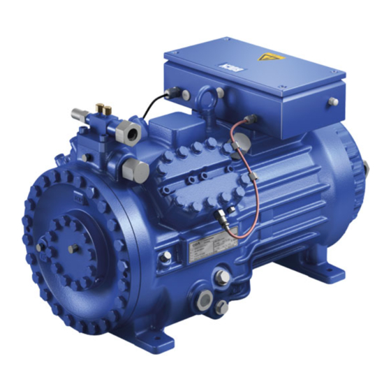
2 | Product description 2.1 Short description • Semi-hemetic four-cylinder reciprocating compressor with suction gas cooled driving motor. • T he flow of refrigerant sucked in from the evaporator is led over the engine and provides for a particularly intensive cooling. Thus the engine can be kept special during high load on a relatively low temperature level. •... -
Page 7: Type Key
2 | Product description 2.2 Name plate (example) GEA Bock GmbH 72636 Frickenhausen, Germany HGX34/230-4 S CO 20,1 AS12345-001 59,8 A 24,1 231 A 283 A CO2,C 85 E 100/150 bar Fig. 3 Voltage, circuit, frequency Type designation 50 Hz Nominal rotation speed... -
Page 8: Areas Of Application
3 | Areas of application 3.1 Refrigerants • CO : R744 (Recommendation CO quality 4.5 (< 5 ppm H 3.2 Oil charge The compressors are filled at the factory with the following oil type: Compressor version ML and S: GEA C85E GEA C150E Compressor version SH: (only this oils may be used) ATTENTION Property damage possible. max. The oil level must be in the visible part of the sight glass;... - Page 9 3 | Areas of application Einsatzgrenzen HGX34+46 CO Compressor version ML (bar) ?t = 10 K (bar) 64,3 (°C) Unlimited Fig. 5 application range Max. permissible operating (bar) pressure (LP/HP) : 100/150 bar Evaporation temperature (°C) ∆t Suction gas superheat (K) LP = Low pressure Suction pressure (bar) HP = High pressure Discharge end pressure (bar)
- Page 10 (bar) 64,3 3 | Areas of application (°C) Compressor version S (bar) ?t = 10 K (bar) 64,3 (°C) Unlimited Fig. 6 application range Max. permissible operating (bar) pressure (LP/HP) : 100/150 bar Evaporation temperature (°C) ∆t Suction gas superheat (K) LP = Low pressure Suction pressure (bar) HP = High pressure Discharge end pressure (bar)
- Page 11 (bar) 64,3 3 | Areas of application (°C) Compressor version SH (bar) ?t = 10 K (bar) 64,3 (°C) Unlimited Fig. 7 application range Max. permissible operating pressure (LP/HP) : 100/150 bar Evaporation temperature (°C) ∆t Suction gas superheat (K) LP = Low pressure Suction pressure (bar) HP = High pressure Discharge end pressure (bar)
-
Page 12: Compressor Assembly
4| Compressor assembly INFO New compressors are factory-filled with inert gas (3 bar nitrogen). Leave this service charge in the compressor for as long as possible and prevent the ingress of air. Immediately after coolingtechnical connection of the compressor of shutoff devices in suction-, discharge-, oil return line etc. close and compressors evacuate. Check the compressor for transport damage before starting any work. -
Page 13: Connecting The Pipelines - Solder System
4| Compressor assembly 4.3 Connecting the pipelines - solder system ATTENTION Damage possible. Superheating can damage the valve. Remove the pipe supports therefore from the valve for soldering and accordingly cool the valve body during and after soldering. Only solder using inert gas to inhibit oxidation products (scale). Material soldering / welding connection: S235 (JRG2C) The pipe connections have graduated inside diameters so that pipes with standart millimetre and inch dimensions can be used. -
Page 14: Pipes
4| Compressor assembly 4.5 Pipes Pipes and system components must be clean and dry inside and free of scale, swarf and layers of rust and phosphate. Only use hermetically sealed parts. Lay pipes correctly. Suitable vibration compensators must be provided to prevent pipes being cracked and broken by severe vibrations. -
Page 15: Laying Suction And Pressure Lines
4| Compressor assembly 4.8 Laying suction and pressure lines ATTENTION Property damage possible. Improperly installed pipes can cause cracks and tears which can result in a loss of refrigerant. INFO Proper layout of the suction and pressure lines directly after the compressor is integral to the smooth running and vibration behaviour of the system. -
Page 16: Operating Mode Of The Lockable Service Connections
After activating the spindle, generally fit the spindle protection cap again and tighten with 40-50 Nm. This serves as a second sealing feature during operation 4.11 Oil return To ensure the oil return function will work reliably no matter what kind of system configuration you are using, GEA recommends incorporating oil separators or oil level monitoring equipment. The "O" connection is already available from the factory for the purpose of installing the additional oil level monitoring component. Oil should be returned from the oil separator to the compressor via the "D1" connection provided for this purpose on the compressor. -
Page 17: Electrical Connection
5| Electrical connection Electrical connection DANGER Risk of electric shock! High voltage! Only carry out work when the electrical system is disconnected from the power supply! ATTENTION When attaching accessories with an electrical cable, a minimum bending radius of 3 x the cable diameter must be maintained for laying the cable. INFO Connect the compressor motor in accordance with the circuit diagram (see inside of terminal box). -
Page 18: Standard Motor, Designed For Direct Or Part Winding Start
5| Electrical connection 5.2 Standard motor, designed for direct or part winding start Designation on the name plate Sticker on the terminal box Y/YY Compressors marked in this way are suitable for direct or part winding start. The motor winding is divided into two parts: part winding 1 = 66% and part winding 2 = 33%. This winding devision reduces the start-up current during a part winding start to approx. - Page 19 5| Electrical connection In the factory, the motor is switched for direct starting (YY). For part winding start (Y/YY), remove the bridges and connect the motor feed cable according to the circuit diagram: 400 V Direct start YY Part winding start Y/YY ATTENTION Property damage possible.
- Page 20 5| Electrical connection 5.3 Basic circuit diagram for part winding start --> compressor with MP10 FC1.2 FC1.1 I> I> I> I> I> I> FC1.1 FC1.2 X1 L1 L1 N N 43 43 11 Y/YY X2 1 MP10 Compressor terminal box Θ...
- Page 21 L1.1 L2.1 L3.1 L1.2 P> P-Öl FC1.1 Motor protection switch (part winding 1) FC1.2 Motor protection switch (part winding 2) Control power circuit fuse Delay relay max. 1s Main switch 6.1.8 Mains contactor (part winding 1) Mains contactor (part winding 2) Control voltage switch PW INT69 HG44/56...
- Page 22 5| Electrical connection 5.4 Basic circuit diagram for part winding start --> compressor with INT69 G FC1.2 FC1.1 I> I> I> I> I> I> FC1.1 FC1.2 B1 B2 Y/YY INT69 Θ Θ Compressor terminal box Anschlußkasten Verdichter Fig. 25 Oil pressure safety switch High pressure safety monitor Safety chain (high/low pressure monitoring) Cold conductor (PTC sensor) motor winding...
- Page 23 L1.1 L2.1 L3.1 L1.2 P> P-Öl FC1.1 Motor protection switch (part winding 1) FC1.2 Motor protection switch (part winding 2) Control power circuit fuse Delay relay max. 1s 6.2.8 Main switch Mains contactor (part winding 1) Mains contactor (part winding 2) Control voltage switch PW INT69 HG44/56 BOCK COMPRESSORS...
-
Page 24: Special Motor: Design For Direct Or Star-Delta Start
5| Electrical connection 5.5 Special motor: design for direct or star-delta start Designation on the name plate Sticker on the terminal box ∆ / Y... - Page 25 5| Electrical connection Star-delta start-up is only possible for 230 V power supply. Example: 230 V ∆ 400 V Y Direct start Star-delta start Direct start only...
- Page 26 5| Electrical connection 5.6 Stern-Dreieck-Anlauf mit Sondermotor --> Verdichter mit MP10 5.6 Basic circuit diagram for star-delta start with special motor --> compressor with MP10 FC1.1 I> I> I> FC1.1 FC1.2 FC1.2 I> I> I> X1 L1 L1 N N 43 43 11 ˜...
- Page 27 L1.1 L2.1 L3.1 L1.2 P> P-Öl FC1.1/1.2 Motor protection switch Control power circuit fuse Delay relay for contactor changeover 2.1.5 2.1.8 2.1.8 Main switch 2.1.7 Mains contactor 14 2.5 Δ-contactor Y-contactor Control voltage switch INT69 HG44/56 BOCK COMPRESSORS...
-
Page 28: Electronic Trigger Unit Mp10
5| Electrical connection 5.7 Electronic trigger unit MP10 The compressor motor is fitted with cold conductor temperature sensors (PTC) connected to the elec- tronic trigger unit MP10 in the terminal box. Readiness to operate is signalled by the H3 LED (green) after the power supply is applied. In the case of excess temperature in the motor winding, the unit switches off the compressor and the H1 LED lights red. - Page 29 5| Electrical connection 5.9 Function test of the trigger unit MP10 Before start-up, troubleshooting or making changes to the control power circuit, check the functionality of the trigger unit: LED H1 LED H2 LED H3 Procedure green • Interrupt power supply (L1 or SF1) •...
-
Page 30: Oil Sump Heater
5| Electrical connection 5.10 Basic circuit diagram for star-delta start with special motor --> compressor with INT69 G FC1.1 I> I> I> FC1.1 FC1.2 FC1.2 I> I> I> B1 B2 ˜ OG OG INT69 Θ Θ Anschlußkasten Verdichter Compressor terminal box Fig. - Page 31 L1.1 L2.1 L3.1 L1.2 P> P-Öl FC1.1/1.2 Motor protection switch Control power circuit fuse Delay relay for contactor changeover 2.2.8 2.2.8 2.2.5 Main switch 2.2.7 Mains contactor 14 2.5 Δ-contactor Y-contactor Control voltage switch INT69 HG44/56 BOCK COMPRESSORS...
- Page 32 5| Electrical connection 5.11 Electronic trigger unit INT69 G The compressor motor is fitted with cold conductor temperature sensors (PTC) connected to the electronic trigger unit INT69 G in the terminal box. In case of excess temperature in the motor winding, the INT69 G deactivates the motor contactor.
- Page 33 5| Electrical connection 5.13 Function test of the trigger unit INT69 G Before commissioning, after troubleshooting or making changes to the control power circuit, check the functionality of the trigger unit. Perform this check using a continuity tester or gauge. Relay position INT69 G Gauge state Relay position...
-
Page 34: Commissioning
6| Commissioning 6.1 Preparations for start-up INFO In order to protect the compressor against inadmissible operating conditions, high-pressure and low-pressure pressostats controls are mandatory on the installation side. The compressor has undergone trials in the factory and all functions have been tested. There are therefore no special running-in instructions. Check the compressor for transport damage! WARNING When the compressor is not running, depending on ambient... -
Page 35: Evacuation
6| Commissioning 6.4 Evacuation ATTENTION Do not start the compressor if it is under vacuum. Do not apply any voltage - even for test purposes (must only be operated with refrigerant). Under vacuum, the spark-over and creepage current distances of the terminal board connection bolts shorten;... -
Page 36: Start-Up
6| Commissioning 6.6 Start-up WARNING Ensure that both shut-off valves are open before starting the compressor! Check that the safety and protection devices (pressure switch, motor protection, electrical contact protection measures, etc.) are functioning properly. Switch on the compressor and let it run for at least 10 minutes. The machine should reach a state of equilibrium. -
Page 37: Decompression Valves
6| Commissioning 6.8 Decompression valves ATTENTION The compressor is fitted with two decompression valves. One valve each on the suction and discharge side. If excessive pressures are reached, the valves open and prevent further pressure increase. Thereby CO is blown off to the ambient! In the event that a pressure relief valve activates repeatedly, check valve and replace if necessary as during blow-off extreme condi- tions can occure, which may result in a permanent leak. Always check system for refrigerant loss after activation of pressure relief valve! The decompression valves do not replace any pressure switches... -
Page 38: Filter Dryer
6| Commissioning 6.9 Avoid slugging ATTENTION Slugging can result in damage to the compressor and cause refrigerant to leak. To prevent slugging: The complete refrigeration plant must be properly designed. All components must be compatibly rated with each other with regard to output (particularly the evaporator and expansion valves). -
Page 39: Work To Be Carried Out
Set oil sump heater , 230 V AC 80854 Only use genuine GEA spare parts! 7.4 Accessories Available accessories can be found on the Internet at www.gea.com. 7.5 Lubricants For operation with CO the GEA oil C 85 E is necessary! 7.6 Decommissioning Close the shut-off valves on the compressor. -
Page 40: Technical Data
8| Technical data Oil charge Weight 380-420 V Y/YY - 3 - 50 Hz PW 440-480 V Y/YY - 3 - 60 Hz PW PW = Part Winding, Winding ratios: 66% /33% No. of cylinders... - Page 41 8| Technical data 380-420 V Y/YY - 3 - 50 Hz PW 440-480 V Y/YY - 3 - 60 Hz PW PW = Part Winding, Winding ratios: 66% /33%...
-
Page 42: Dimensions And Connections
10951 HGX34/230-4 SH CO2 T 10953 Halbhermetischer Verdichter HG / Semi-hermetic compressor HG Halbhermetischer Verdichter HG / Semi-hermetic compressor HG Anschluss Ö HGX34/130-4 ML CO2 T 10941 HGX34/170-4 ML CO2 T 10943 HGX34/210-4 ML CO2 T 10945 HGX34/290-4 ML CO2 T... - Page 43 9| Dimensions and connections Suction line see technical data, chapter 8 Discharge line Connection suction side, not lockable 16 “ UNF Connection suction side, lockable 16 “ UNF Connection suction side, not lockable 8 “ NPTF Connection discharge side, not lockable 16 “...
-
Page 44: Declaration Of Installation
DECLARATION OF INSTALLATION for using the compressors within the European Union (in accordance with Machinery Directive 2006/42/EC) The manufacturer: GEA Bock GmbH, Benzstraße 7 72636 Frickenhausen, Tel.: 07022/9454-0 hereby declares that the refrigerating compressor HGX34 CO T complies with the basic requirements of Appendix II 1B of the Machinery Directive 2006/42/EC. -
Page 45: Service
11| Service Dear customer, GEA compressors are top-quality, reliable and service-friendly quality products. If you have any questions about installation, operation and accessories, please contact our technical service or specialist wholesaler and/or our representative. The GEA service team can be contacted by phone with a toll-free hotline 00 800 / 800 000 88 or via e-mail: refrigeration@gea.com. Yours faithfully GEA Bock GmbH Benzstraße 7... - Page 46 • • GEA Group is a global engineering company with multi-billion euro sales and operations in more than 50 countries. Founded in 1881, the company is one of the largest providers of innovative equipment and process technology. GEA Group is listed in the STOXX Europe 600 index.
Need help?
Do you have a question about the HGX34/130-4 ML CO2 T and is the answer not in the manual?
Questions and answers