GEA HG34e Assembly Instructions Manual
Bock compressor
Hide thumbs
Also See for HG34e:
- Maintenance manual (40 pages) ,
- Assembly instructions manual (32 pages)
Table of Contents
Advertisement
Quick Links
Bock Compressor HG34e
Assembly instructions
HG34e/215-4
HG34e/255-4
HG34e/315-4
HG34e/380-4
HG34e/215-4 S
HG34e/255-4 S
HG34e/315-4 S
HG34e/380-4 S
engineering for a better world
HGX34e/215-4
HGX34e/255-4
HGX34e/315-4
HGX34e/380-4
HGX34e/215-4 S
HGX34e/255-4 S
HGX34e/315-4 S
HGX34e/380-4 S
HGX34e/215-4 S R407C
HGX34e/255-4 S R407C
HGX34e/315-4 S R407C
HGX34e/380-4 S R407C
GEA Refrigeration Technologies
D
GB
F
E
1
Advertisement
Table of Contents

Related Manuals for GEA HG34e


Summary of Contents for GEA HG34e
- Page 1 Bock Compressor HG34e Assembly instructions HG34e/215-4 HGX34e/215-4 HGX34e/215-4 S R407C HG34e/255-4 HGX34e/255-4 HGX34e/255-4 S R407C HG34e/315-4 HGX34e/315-4 HGX34e/315-4 S R407C HG34e/380-4 HGX34e/380-4 HGX34e/380-4 S R407C HG34e/215-4 S HGX34e/215-4 S HG34e/255-4 S HGX34e/255-4 S HG34e/315-4 S HGX34e/315-4 S HG34e/380-4 S HGX34e/380-4 S...
- Page 2 About these instructions Read these instructions before assembly and before using the compressor. This will avoid misunder- standings and prevent damage. Improper assembly and use of the compressor can result in serious or fatal injury. Observe the safety instructions contained in these instructions. These instructions must be passed onto the end customer along with the unit in which the compres- sor is installed. Manufacturer GEA Bock GmbH 72636 Frickenhausen Contact GEA Bock GmbH Benzstraße 7 72636 Frickenhausen Germany Telephone +49 7022 9454 0 Fax +49 7022 9454 137 bock@gea.com www.bock.de...
-
Page 3: Table Of Contents
Contents Page Safety 1.1 Identification of safety instructions 1.2 Qualifications required of personnel 1.3 General safety instructions 1.4 Intended use Product description 2.1 Short description 2.2 Name plate 2.3 Type key Areas of application 3.1 Refrigerants 3.2 Oil charge 3.3 Limits of application 3.4 Refrigerants - design for R407C, 35 bar 3.5 Oil charge for R407C, 35 bar 3.6 Limits of application, R407C, 35 bar Compressor assembly 4.1 Setting up 4.2 Pipe connections 4.3 Pipes 4.4 Laying suction and pressure lines 4.5 Operating the shut-off valves... -
Page 4: Safety
1| Safety 1.1 Identification of safety instructions: Indicates a dangerous situation which, if not DANGER! avoided, will cause immediate fatal or serious injury. Indicates a dangerous situation which, if not WARNING! avoided, may cause fatal or serious injury. Indicates a dangerous situation which, if not CAUTION! avoided, may cause fairly severe or minor injury. Indicates a situation which, if not ATTENTION! avoided, may cause property damage. INFO! Important information or tips on simplifying work. 1.2 Qualifications required of personnel WARNING! I nadequately qualified personnel poses the risk of accidents, the consequence being serious or fatal injury. Work on compressors must therefore only be performed by personnel with the qualifica- tions listed below: • F or example, a refrigeration technician, refrigeration mechatron-... -
Page 5: Intended Use
1| Safety 1.4 Intended use These assembly instructions describe the standard version of the HG34e manufactured by Bock. The compressor is intended for use in refrigeration systems in compliance with the limits of application. Only the refrigerant specified in these instructions may be used. Any other use of the compressor is prohibited! WARNING! The compressor may not be used in potentially explosive environments! The Bock refrigerating compressor named in the title is intended for installing in a machine (within the EU according to the EU Directives 2006/42/EC Machinery Directive, 97/23/EC Pressure Equipment Directive and 2006/95/EC – Low Voltage Directive). Commissioning is only permissible if the compressor has been installed in accordance with these a ssembly instructions and the entire system into which it is integrated has been inspected and... -
Page 6: Product Description
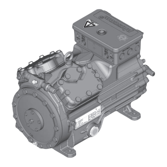
2| Product description 2.1 Short description • Semi-hermetic four-cylinder reciprocating compressor with oil pump lubrication. • Suction gas cooled drive motor. Transport eyelet Valve plate Discharge shut-off valve Name plate Oil pump Oil sight glass Fig. 1 Terminal box Cylinder cover Drive section Motor section Suction shut- off valve Fig. 2 Dimension and connection values can be found in Chapter 9... -
Page 7: Type Key
2| Product description 2.2 Name plate (example) GEA Bock GmbH 72636 Frickenhausen, Germany HGX34e/315-4 AS38125A001 27,3 21,1/12,2A 111A 32,8 19/28 IP66 SE 55 Fig. 3 Type designation Voltage, circuit, frequency 50 Hz Machine number Nominal rotation speed maximum operating current Displacement Starting current (rotor blocked) Voltage, circuit, frequency 60 Hz ND LP: max. admissible operating pressure 10 Nominal rotation speed (g) Low pressure side 11 Displacement HD (HP): max. admissible operating... -
Page 8: Areas Of Application
3| Areas of application 3.1 Refrigerants • HFKW / HFC: R134a, R404A/R507, R407C • (H)FCKW / (H)CFC: 3.2 Oil charge The compressors are filled at the factory with the following oil type: - for R134a, R404A/R507, R407C FUCHS Reniso Triton SE 55 - for R22 FUCHS Reniso SP 46 Compressors with ester oil charge (FUCHS Reniso Triton SE 55) are marked with an X in the type designation (e.g. HGX34e/380-4). INFO! For refilling, we recommend the above oil types. Alternatives: see lubricants table, Chapter 7.5. ATTENTION! The oil level must be in the visible part of the sight max. oil level glass; damage to the com- min. oil level pressor is possible if over- Fig. 4... - Page 9 3| Areas of application R134a Fig. 5 R407C Fig. 6 Unlimited application range Supplementary cooling or reduced suction gas temperature Supplementary cooling and reduced suction gas temperature Motor version S R404A/R507 (more powerful motor) Evaporation temperature (°C) Condensing temperature (°C) Suction gas superheat (K) Fig. 7 Suction gas temperature (°C) Max. permissible operating pressure (LP/HP) : 19/28 bar LP = Low pressure HP = High pressure Design for other areas on request Fig. 8...
-
Page 10: Refrigerants - Design For R407C, 35 Bar
3| Areas of application 2 | Produktbeschreibung 2 | Produktbeschreibung 2 | Produktbeschreibung 3 .4 Refrigerant - Design for R407C, 35 bar 2.2 Typschild (Beispiel) 2.2 Typschild (Beispiel) 2.2 Typschild (Beispiel) • HFKW / HFC: R407C HGX34e/315-4 S R407C HGX34e/315-4 S R407C HGX34e/315-4 S R407C Only compressors with the additional designation AS38125A001 AS38125A001 AS38125A001... - Page 11 3| Areas of application 3.6 Limits of application for R407C, 35 bar R407C Fig. 10 Unlimited application range Max. permissible operating pressure (LP/HP) : 19/35 bar Verdampfungstemperatur (°C) Evaporation temperature (°C) LP = low pressure Verflüssigungstemperatur (°C) Condensing temperature (°C) HP = high pressure Sauggastemperatur (°C) Suction gas temperature (°C) Design for other areas on request...
-
Page 12: Compressor Assembly
4| Compressor assembly INFO! New compressors are factory-filled with inert gas (3 bar nitrogen). Leave this service charge in the compressor for as long as possible and prevent the ingress of air. Check the compressor for transport damage before starting any work. 4.1 Setting up Use transport eyelet. Do not lift manually! Use lifting gear! Fig. 11 Provide adequate clearance for maintenance work. -
Page 13: Pipes
4| Compressor assembly 4.3 Pipes Pipes and system components must be clean and dry inside and free of scale, swarf and layers of rust and phosphate. Only use air-tight parts. Lay pipes correctly. Suitable vibration compensators must be provided to prevent pipes being cracked and broken by severe vibrations. Ensure a proper oil return. Keep pressure losses to an absolute minimum. 4.4 Laying suction and pressure lines INFO! Proper layout of the suction and pressure lines directly after the compressor is integral to the smooth running and vibration behaviour of the system. -
Page 14: Operating The Shut-Off Valves
4| Compressor assembly 4.5 Operating the shut-off valves Before opening or closing the shut-off valve, release the valve spindle seal by approx. ¼ of a turn counter-clockwise. After activating the shut-off valve, re-tighten the adjustable valve spindle seal clockwise. Release Tighten Valve spindle seal Fig. 17 Fig. 18 4.6 Operating mode of the lockable service connections Service connec- tion closed Pipe connection Spindle Connection blocked Compressor Fig. 19 Opening the shut-off valve: Spindle: turn to the left (counter-clockwise) as far as it will go. —> Shut-off valve completely opened / service connection closed. Service connec- tion opened Pipe connection Connection Spindle open Compressor Fig. 20 Opening the service connection... -
Page 15: Electrical Connection 15 Dgb
5| Electrical connection Electrical connection DANGER! H igh voltage! Risk of electric shock! Only carry out work when the electrical system is disconnected from the power supply! INFO! C onnect the compressor motor in accordance with the circuit diagram (see inside of terminal box). U se suitable cable entry point of the correct protection type (see name plate) for routing cables into the terminal box. I nsert the strain reliefs and prevent chafe marks on the cables. -
Page 16: Circuit Diagram For Direct Start 230 V Δ / 400 V Y E
5.3 Circuit diagramm for direct start 230 V ∆ / 400 V Y ... - Page 17 Alarm Motor protection Overheating R1, R2 Alarm high pressure XSS Terminal strip in the external switch cabinet ...
-
Page 18: Start Unloader
5| Electrical connection 5.4 Start unloader To avoid current peaks during the starting phase we recommend using the Bock-ESS soft starting device (Electronic Soft Start). Refer to "Accessories" for further information. 5.5 Electronic trigger unit MP 10 The compressor motor is fitted with cold conductor temperature sensors (PTC) connected to the electronic trigger unit MP 10 in the terminal box. Readiness to operate is signalled by the H3 LED (green) after the power supply is applied. In the case of excess temperature in the motor winding, the unit switches off the compressor and the H1 LED lights red. The hot gas side of the compressor can also be protected against overtemperature using a thermal protection thermostat (accessory). The H2 LED (red) is provided for the protection function. The unit trips when an overload or inadmissible operating conditions occur. Find and remedy the cause. - Page 19 5| Electrical connection 5.7 Function test of the trigger unit MP 10 Before start-up, troubleshooting or making changes to the control power circuit, check the functionality of the trigger unit: LED H1 LED H2 LED H3 Procedure green • Interrupt power supply (L1 or S1) • Release the motor temperature sensor connection (1 or 2) • Release the hot gas temperature sensor (if installed) (3 or 4) • Restore the power supply (L1 or S1) •...
-
Page 20: Commissioning
6| Commissioning 6.1 Preparations for start-up INFO! In order to protect the compressor against inadmissible operating conditions, high-pressure and low-pressure pressostats controls are mandatory on the installation side. The compressor has undergone trials in the factory and all functions have been tested. There are therefore no special running-in instructions. Check the compressor for transport damage! 6.2 Pressure strength test DANGER! Bursting! The compressor must only be pressurised using nitrogen ). Never pressurise with oxygen or other gases! The maximum permissible overpressure of the compressor must not be exceeded at any time during the testing process (see name plate data)! Do not mix any refrigerant with the nitrogen as this could... -
Page 21: Refrigerant Charge
6| Commissioning 6.5 Refrigerant charge CAUTION! Wear personal protective clothing such as goggles and protective gloves! Make sure that the suction and pressure line shut-off valves are open. With the compressor switched off, add the liquid refrigerant directly to the condenser or receiver, breaking the vacuum. If the refrigerant needs topping up after starting the compressor, it can be topped up in vapour form on the suction side, or, taking suitable precautions, also in liquid form at the inlet to the evaporator. INFO! Avoid overfilling the system with refrigerant! I n order to prevent shifts in concentration, zeotropic refrigerant blends (e.g. R407C) must always only be added to the refrigerating system in liquid form. -
Page 22: Connection Of Oil Level Regulator
200 operating hours, then approx. every 3 years or 10,000 - 12,000 operating hours. Dispose of used oil according to the regulations; observe national regulations. Annual checks: Oil level, leak tightness, running noises, pressures, temperatures, function of a uxiliary devices such as oil sump heater, pressure switch. 7.3 Spare parts recommendation 215-4 (S) 315-4 (S) 215-4 S R407C 315-4 S R407C HG34e / ... 255-4 (S) 380-4 (S) 255-4 S R407C 380-4 S R407C Designation Ref. No. Ref. No. Ref. No. -
Page 23: Accessories
7| Maintenance 7.4 Accessories Available accessories can be found on the Internet at www.bock.de. 7.5 Extract from the lubricants table The oil type filled as standard in the factory is marked on the name plate . This oil type should be used as a preference. Alternatives are stated in the extract from our lubricants table below. Refrigerants Bock standard oil types Recommended alternatives Fuchs Reniso Triton SEZ 32 Esso/Mobil EAL Arctic 46 Fuchs Reniso Triton SE 55 (e.g. R134a, R407C, Sunoco Suniso SL 46 R404A) Texaco Capella HFC 55 Fuchs Reniso SP 32 BP Energol LPT 46 HCFC (e.g. R22) Fuchs Reniso SP 46 Sunoco Suniso 3,5 GS Texaco Capella WF 46... -
Page 24: Technical Data
8| Technical data 220-240 V ∆ / 380-420 V Y - 3 - 50 Hz 265-290 V ∆ / 440-480 V Y - 3 - 60 Hz... - Page 25 8| Technical data 220-240 V ∆ / 380-420 V Y - 3 - 50 Hz 265-290 V ∆ / 440-480 V Y - 3 - 60 Hz...
-
Page 26: Dimensions And Connections
9| Dimensions and connections HG34e ca.285 Centre of gravity H,D1 Vibration Schwingungs- dämpfer damper Dimensions in mm SV 90° rotatable Fig. 23 Suction line see technical data, Chapter 8 Discharge line Connection suction side, not lockable 8 “ NPTF Connection suction side, lockable 16 “ UNF Connection discharge side, not lockable 8 “ NPTF Connection discharge side, lockable 16 “ UNF Connection oil return from oil separator 4 “ NPTF Connection oil pressure gauge 8 “ NPTF... - Page 27 9| Dimensions and connections HG34e R407C ca.285 ca.285 Centre of gravity H,D1 H,D1 ca.165 ca.165 ca.540 ca.540 Vibration Schwingungs- Schwingungs- damper dämpfer dämpfer Dimensions in mm SV 90° rotatable Fig. 24 Suction line see technical data, Chapter 8 Discharge line Connection suction side, not lockable 8 “ NPTF Connection suction side, lockable 16 “ UNF Connection discharge side, not lockable 8 “ NPTF Connection discharge side, lockable 16 “...
-
Page 28: Declaration Of Conformity And Installation
10| Declaration of conformity and installation DECLARATION OF CONFORMITY CE 03 for using the compressors within the European Union (in accordance with Low Voltage Directive 2006/95/EC) We hereby declare that the following refrigerating compressors Product designation: HG34e comply with the Low Voltage Directive 2006/95/EC. Applied harmonised standard: EN 60034-1:2010 EN 60204-1:2006 DECLARATION OF INSTALLATION for using the compressors within the European Union (in accordance with Machinery Directive 2006/42/EC) The manufacturer: GEA Bock GmbH, Benzstraße 7 72636 Frickenhausen, Tel.: 07022/9454-0 hereby declares that the refrigerating compressor HG34e complies with the basic requirements of Appendix II 1B of the Machinery Directive 2006/42/EC. Applied harmonised standard: EN 12693:2008 and the corresponding standards referenced A partly completed machine may only be put into operation when it has been established that the machine, into which the partly completed machine is to be installed, conforms to the r egulations of the Machinery Directive (2006/42/EC). The manufacturer undertakes to transmit electronically the special documentation required by individual states for partly completed machinery on request. The special technical documentation required for partly completed machinery has been created in accordance with Appendix VII Part B. -
Page 29: Service
11| Service Dear customer, Bock compressors are top-quality, reliable and service-friendly quality products. If you have any questions about installation, operation and accessories, please contact our technical service or specialist wholesaler and/or our representative. The Bock service team can be contacted by phone with a toll-free hotline 00 800 / 800 000 88 or via e-mail: bock@gea.com. Yours faithfully GEA Bock GmbH Benzstraße 7 72636 Frickenhausen Germany We also provide information on the Internet at www.bock.de. For example, under the "Documentation" link you will find: - Technical information - Product information - Product brochures - and much more... - Page 30 • • GEA Group is a global engineering company with multi-billion euro sales and operations in more than 50 countries. Founded in 1881, the company is one of the largest providers of innovative equipment and process technology. GEA Group is listed in the STOXX® Europe 600 index.
Need help?
Do you have a question about the HG34e and is the answer not in the manual?
Questions and answers