GEA HGX34 CO2 T Series Assembly Instructions Manual
Bock compressor
Hide thumbs
Also See for HGX34 CO2 T Series:
- Repair instruction (24 pages) ,
- Assembly instructions manual (46 pages)
Table of Contents
Advertisement
Quick Links
Bock Compressor HGX34 CO
Assembly instructions
HGX34/110-4 ML CO
2
HGX34/130-4 ML CO
2
HGX34/150-4 ML CO
2
HGX34/170-4 ML CO
2
HGX34/190-4 ML CO
2
HGX34/210-4 ML CO
2
HGX34/230-4 ML CO
2
engineering for a better world
2
T
HGX34/110-4 S CO
T
HGX34/130-4 S CO
T
HGX34/150-4 S CO
T
HGX34/170-4 S CO
T
HGX34/190-4 S CO
T
HGX34/210-4 S CO
T
HGX34/230-4 S CO
T
T
HGX34/110-4 SH CO
2
T
HGX34/130-4 SH CO
2
T
HGX34/150-4 SH CO
2
T
HGX34/170-4 SH CO
2
T
HGX34/190-4 SH CO
2
T
HGX34/210-4 SH CO
2
T
HGX34/230-4 SH CO
2
GEA Refrigeration Technologies
D
GB
F
E
T
2
T
2
T
2
T
2
T
2
T
2
T
2
1
Advertisement
Table of Contents

Related Manuals for GEA HGX34 CO2 T Series


Summary of Contents for GEA HGX34 CO2 T Series
- Page 1 HGX34/170-4 S CO HGX34/170-4 SH CO HGX34/190-4 ML CO HGX34/190-4 S CO HGX34/190-4 SH CO HGX34/210-4 ML CO HGX34/210-4 S CO HGX34/210-4 SH CO HGX34/230-4 ML CO HGX34/230-4 S CO HGX34/230-4 SH CO engineering for a better world GEA Refrigeration Technologies...
- Page 2 Observe the safety instructions contained in these instructions. These instructions must be passed onto the end customer along with the unit in which the compres- sor is installed. Manufacturer GEA Bock GmbH 72636 Frickenhausen Contact GEA Bock GmbH Benzstraße 7...
-
Page 3: Table Of Contents
Contents Page Safety 1.1 Identification of safety instructions 1.2 Qualifications required of personnel 1.3 Safety instructions 1.4 Intended use Product description 2.1 Short description 2.2 Name plate 2.3 Type key Areas of application 3.1 Refrigerants 3.2 Oil charge 3.3 Limits of application Compressor assembly 4.1 Setting up 4.2 Pipes 4.3 Flange shut-off valves (HP/LP 4.4 Option: cutting ring screw joint (HP/LP) -
Page 4: Safety
1 | Safety 1.1 Identification of safety instructions: DANGER Indicates a dangerous situation which, if not avoided, will cause immediate fatal or serious injury WARNING Indicates a dangerous situation which, if not avoided, may cause fatal or serious injury CAUTION Indicates a dangerous situation which, if not avoided, may immediately cause fairly severe or minor injury. ATTENTION Indicates a situation which, if not avoided, may cause property damage INFO Important information or tips on simplifying work 1.2 Qualifications required of personnel WARNING Inadequately qualified personnel poses the risk of accidents, the consequence being serious or fatal injury. Work on compressors must therefore only be performed by personnel with the qualifications listed below: • F or example, a refrigeration technician, refrigeration mechatronics engineer. -
Page 5: Safety Instructions
1 | Safety 1.3 Safety instructions WARNING Risk of accident. Refrigerating compressors are pressurised machines and t herefore require particular caution and care in handling. The maximum permissible overpressure must not be exceeded, even for testing purposes. Risk of burns! - Depending on the operating conditions, surface temperatures of over 60 °C on the pressure side or below 0 °C on the suction side can be reached. - Avoid the contact with refrigerant under any circumstances. -
Page 6: Product Description
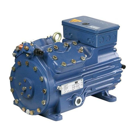
2 | Product description 2.1 Short description • Semi-hemetic four-cylinder reciprocating compressor with suction gas cooled driving motor. • T he fl ow of refrigerant sucked in from the evaporator is led over the engine and provides for a particularly intensive cooling. Thus the engine can be kept special during high load on a relatively low temperature level. • O ne decompression valve each on the low and high pressure side, which vent into the amosphere when these inadmissibly high printing pressures are reached. Transport eyelet Valve plate Name plate... -
Page 7: Type Key
2 | Product description 2.2 Name plate (example) GEA Bock GmbH 72636 Frickenhausen, Germany HGX34/230-4 S CO 20,1 AS12345-001 59,3 A 24,1 231 A 283 A CO2,C 85 E 100/150 bar Fig. 3 Voltage, circuit, frequency Type designation 50 Hz Nominal rotation speed... -
Page 8: Areas Of Application
3 | Areas of application 3.1 Refrigerants • CO : R744 (Recommendation CO quality 4.5 (< 5 ppm H 3.2 Oil charge The compressors are filled at the factory with the following oil type: Compressor version ML and S: Bock C85E Compressor version SH: Bock C150E (only this oils may be used) ATTENTION Property damage possible. max. oil level The oil level must be in the visible part of the sight glass;... - Page 9 3 | Areas of application Einsatzgrenzen HGX34 CO Compressor version ML (bar) ?t = 10 K (bar) 64,3 (°C) Unlimited Fig. 5 application range Max. permissible operating (bar) pressure (LP/HP) : 100/150 bar Evaporation temperature (°C) ∆t Suction gas superheat (K) LP = Low pressure Suction pressure (bar) HP = High pressure Discharge end pressure (bar)
-
Page 10: Connection Of The Electronic Trigger Unit Mp
(bar) 64,3 3 | Areas of application (°C) Compressor version S (bar) ?t = 10 K (bar) 64,3 (°C) Unlimited Fig. 6 application range Max. permissible operating (bar) pressure (LP/HP) : 100/150 bar Evaporation temperature (°C) ∆t Suction gas superheat (K) LP = Low pressure Suction pressure (bar) HP = High pressure Discharge end pressure (bar) - Page 11 (bar) 64,3 3 | Areas of application (°C) Compressor version SH (bar) ?t = 10 K (bar) 64,3 (°C) Unlimited Fig. 7 application range Max. permissible operating pressure (LP/HP) : 100/150 bar Evaporation temperature (°C) ∆t Suction gas superheat (K) LP = Low pressure Suction pressure (bar) HP = High pressure Discharge end pressure (bar)
-
Page 12: Compressor Assembly
4| Compressor assembly INFO New compressors are factory-fi lled with inert gas (3 bar nitrogen). Leave this service charge in the compressor for as long as possible and prevent the ingress of air. Immediately after coolingtechnical connection of the compressor of shutoff devices in suction-, discharge-, oil return line etc. close and compressors evacuate. Check the compressor for transport damage before starting any work. 4.1 Setting up Use transport eyelet. -
Page 13: Flange Shut-Off Valves
4| Compressor assembly 4.3 Flange shut-off valves (HP/LP) CAUTION Risk of injury. The compressor must be depressurised through connections A and B before commencing any work and prior to connecting to the refrigerant system. Fig. 12 Fig. 13 4.4 Option: cutting ring screw joint (HP/LP) ATTENTION Property damage possible. The compressor as delivered is equipped with Schrader valves on the high and low pressure connections. These are used exclusively for changing with inert gas in the factory, and under no circum- stances may they be connected to the refrigeration circuit (the Schrader valves are approved for overpressure up to 28 bar only)! -
Page 14: Operating Mode Of The Lockable Service Connections
4| Compressor assembly 4.5 Operating mode of the lockable service connections Connection cannot Service connection be shut off closed Pipe connection Connection Spindle blocked Fig. 16 Opening the shut-off valve: Compressor Spindle: turn to the left (counter-clockwise) as far as it will go. —> Shut-off valve completely opened / service connection closed. The connection which cannot be shut off is intended for safety devices. -
Page 15: Connecting The Pipelines - Cut Ring System
4| Compressor assembly 4.7 Connecting the pipelines - cut ring system • On its high-pressure side, the compressor has a shut-off valve with multi-sided cutting ring for safe installation of the discharge line. Cutting ring function before tightening the union nut Collar Fig. -
Page 16: Connecting The Pipelines - Solder System
4| Compressor assembly 4.8 Connecting the pipelines - solder system ATTENTION Property damage possible. Remove the valve from the compressor for soldering. Superhea- ting can damage the valve. Cool the valve body during soldering. Only solder using inert gas to inhibit oxidation products (scale). The pipe connections have graduated inside diameters so that pipes with standart millimetre and inch dimensions can be used. -
Page 17: Oil Return
4| Compressor assembly 4.10 Oil return To ensure the oil return function will work reliably no matter what kind of system confi gura- tion you are using, GEA Bock recommends incorporating oil separators or oil level monitoring equipment. The "O" connection is already available from the factory for the purpose of instal- ling the additional oil level monitoring component. Oil should be returned from the oil separator to the compressor via the "D1" connection provided for this purpose on the compressor. -
Page 18: Standard Motor, Designed For Direct Or Part Winding Start
5| Electrical connection 5.2 Standard motor, designed for direct or part winding start Designation on the name plate Sticker on the terminal box Y/YY Compressors marked in this way are suitable for direct or part winding start. The motor winding is divided into two parts: part winding 1 = 66% and part winding 2 = 33%. This winding devision reduces the start-up current during a part winding start to approx. - Page 19 5| Electrical connection In the factory, the motor is switched for direct starting (YY). For part winding start (Y/YY), remove the bridges and connect the motor feed cable according to the circuit diagram: 400 V Direct start YY Part winding start Y/YY ATTENTION Property damage possible.
-
Page 20: Basic Circuit Diagram For Part Winding Start
5| Electrical connection 5.3 Basic circuit diagram for part winding start Compressor terminal box Fig. 23 Cold conductor (PTC sensor) motor winding Thermal protection thermostat (PTC sensor) F1.1 / 1.2 2 motor protection switches (66% / 33% of I total) Control power circuit fuse High pressure safety monitor Safety chain (high/low pressure monitoring) Release switch (thermostat) - Page 21 Main switch Compressor motor Mains contactor (part winding 1) Mains contactor (part winding 2) Delay relay max. 1s Control voltage switch Oil sump heater...
-
Page 22: Special Motor: Design For Direct Or Star-Delta Start
5| Electrical connection 5.4 Special motor: design for direct or star-delta start Designation on the name plate Sticker on the terminal box ∆ / Y... - Page 23 5| Electrical connection Star-delta start-up is only possible for 230 V power supply. Example: 230 V ∆ 400 V Y Direct start Star-delta start Direct start only...
-
Page 24: Star-Delta Start With Special Motor
5| Electrical connection 5.5 Star-delta start with special motor Compressor terminal box Fig. 24 Cold conductor (PTC sensor) motor winding Thermal protection thermostat (PTC sensor) F1.1 /1.2 2 motor protection switches Control power circuit fuse High pressure safety monitor Safety chain (high/low pressure monitoring) Release switch (thermostat) Main switch... - Page 25 Compressor motor Mains contactor ∆- contactor Y- contactor Delay relay for contactor changeover Control voltage switch Oil sump heater...
-
Page 26: Electronic Trigger Unit Mp
5| Electrical connection 5.6 Electronic trigger unit MP 10 The compressor motor is fi tted with cold conductor temperature sensors (PTC) connected to the electronic trigger unit MP 10 in the terminal box. Readiness to operate is signalled by the H3 LED (green) after the power supply is applied. -
Page 27: Oil Sump Heater
5| Electrical connection 5.8 Function test of the trigger unit MP 10 Before start-up, troubleshooting or making changes to the control power circuit, check the functionality of the trigger unit: LED H1 LED H2 LED H3 Procedure green • Interrupt power supply (L1 or S1) •... -
Page 28: Commissioning
6| Commissioning 6.1 Preparations for start-up INFO In order to protect the compressor against inadmissible opera- ting conditions, high-pressure and low-pressure pressostats controls are mandatory on the installation side. The compressor has undergone trials in the factory and all functions have been tested. There are therefore no special running-in instructions. -
Page 29: Evacuation
6| Commissioning 6.4 Evacuation ATTENTION Do not start the compressor if it is under vacuum. Do not apply any voltage - even for test purposes (must only be operated with refrigerant). Under vacuum, the spark-over and creepage current distances of the terminal board connection bolts shorten;... -
Page 30: Start-Up
6| Commissioning 6.6 Start-up WARNING Ensure that both shut-off valves are open before starting the compressor! Check that the safety and protection devices (pressure switch, motor protection, electrical contact protection measures, etc.) are functioning properly. Switch on the compressor and let it run for at least 10 minutes. The machine should reach a state of equilibrium. -
Page 31: Decompression Valves
6| Commissioning 6.8 Decompression valves ATTENTION The compressor is fitted with two decompression valves. One valve each on the suction and discharge side. If excessive pres- sures are reached, the valves open and prevent further pressure increase. Thereby CO is blown off to the ambient!! In the event that a pressure relief valve activates repeatedly, check valve and replace if necessary as during blow-off extreme conditions can occure, which may result in a permanent leak. Always check system for refrigerant loss after activation of pres- sure relief valve! The decompression valves do not replace any pressure switches and the additional safety valves in the system. -
Page 32: Maintenance
6| Commissioning 6.9 Avoid slugging ATTENTION Slugging can result in damage to the compressor and cause refrigerant to leak. To prevent slugging: The complete refrigeration plant must be properly designed. All components must be compatibly rated with each other with regard to output (particularly the evaporator and expansion valves). -
Page 33: Work To Be Carried Out
7| Maintenance 7.2 Work to be carried out In order to guarantee optimum operational reliability and service life of the compressor, we recommend carrying out servicing and inspection work at regular intervals: Oil change: not mandatory for factory-produced series systems. - f or field installations or when operating near the application limit: for the first time after 100 to 200 operating hours, then approx. every 3 years or 10,000 - 12,000 operating hours. Dispose of used oil according to the regulations;... -
Page 34: Technical Data
8| Technical data Oil charge Weight 380-420 V Y/YY - 3 - 50 Hz PW 440-480 V Y/YY - 3 - 60 Hz PW PW = Part Winding, Winding ratios: 66% /33% No. of cylinders... - Page 35 8| Technical data 380-420 V Y/YY - 3 - 50 Hz PW 440-480 V Y/YY - 3 - 60 Hz PW PW = Part Winding, Winding ratios: 66% /33%...
-
Page 36: Dimensions And Connections
9| Dimensions and connections ca.400 Centre of gravity DV D1 L1 B2 H B1 B ca.250 (230) 606 (547) ca.730 (670) Anschlüsse SV Saugabsperrventil, Rohr DV Druckabsperrventil, Rohr A Anschluß Saugseite, nicht abs A1 Anschluß Saugseite, absperrb B Anschluß Druckseite, nicht abs B1 Anschluß... - Page 37 9| Dimensions and connections Saugleitung siehe technische Daten, Kapitel 8 Druckleitung Connection suction side, not lockable 16 “ UNF Connection suction side, lockable 16 “ UNF Connection discharge side, not lockable 16 “ UNF Connection discharge side, lockable 16 “ UNF Connection discharge side, not lockable 8 “...
-
Page 38: Declaration Of Conformity And Installation
DECLARATION OF INSTALLATION for using the compressors within the European Union (in accordance with Machinery Directive 2006/42/EC) The manufacturer: GEA Bock GmbH, Benzstraße 7 72636 Frickenhausen, Tel.: 07022/9454-0 hereby declares that the refrigerating compressor HGX34 CO T complies with the basic requirements of Appendix II 1B of the Machinery Directive 2006/42/EC. -
Page 39: Service
11| Service Dear customer, Bock compressors are top-quality, reliable and service-friendly quality products. If you have any questions about installation, operation and accessories, please contact our technical service or specialist wholesaler and/or our representative. The Bock service team can be contacted by phone with a toll-free hotline 00 800 / 800 000 88 or via e-mail: bock@gea.com. Yours faithfully GEA Bock GmbH Benzstraße 7 72636 Frickenhausen Germany We also provide information on the Internet at www.bock.de. - Page 40 • • GEA Group is a global engineering company with multi-billion euro sales and operations in more than 50 countries. Founded in 1881, the company is one of the largest providers of innovative equipment and process technology. GEA Group is listed in the STOXX® Europe 600 index.
Need help?
Do you have a question about the HGX34 CO2 T Series and is the answer not in the manual?
Questions and answers