Table of Contents

Subscribe to Our Youtube Channel
Related Manuals for GEA HGX12e S CO2


Summary of Contents for GEA HGX12e S CO2
- Page 1 Bock Compressor HGX12e S CO Assembly instructions HGX12e/20-4 S CO HGX12e/30-4 S CO HGX12e/40-4 S CO HGX12e/50-4 S CO HGX12e/60-4 S CO HGX12e/75-4 S CO engineering for a better world GEA Refrigeration Technologies...
- Page 2 Observe the safety instructions contained in these instructions. These instructions must be passed onto the end customer along with the unit in which the compres- sor is installed. Manufacturer GEA Bock GmbH 72636 Frickenhausen Contact GEA Bock GmbH Benzstraße 7...
-
Page 3: Table Of Contents
Contents Page Safety 1.1 Identification of safety instructions 1.2 Qualifications required of personnel 1.3 General safety instructions 1.4 Intended use Product description 2.1 Short description 2.2 Name plate 2.3 Type key Areas of application 3.1 Refrigerants 3.2 Oil charge 3.3 Limits of application Compressor assembly 4.1 Setting up 4.2 Pipe connections... -
Page 4: Safety
1| Safety 1.1 Identification of safety instructions: DANGER Indicates a dangerous situation which, if not avoided, will cause immediate fatal or serious injury. WARNING Indicates a dangerous situation which, if not avoided, may cause fatal or serious injury. CAUTION Indicates a dangerous situation which, if not avoided, may cause fairly severe or minor injury. -
Page 5: Intended Use
1| Safety 1.3 Safety instructions WARNING Risk of accidents. Refrigerating compressors are pressurised machines and as such call for heightened caution and care in handling. The maximum permissible overpressure must not be exceeded, even for testing purposes. Risk of burns! - Depending on the operating conditions, surface temperatures of over 60°C on the discharge side or below 0°C on the suction side can be reached. -
Page 6: Product Description
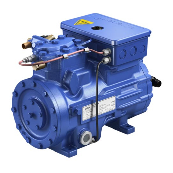
2| Product description 2.1 Short description • Semi-hermetic two-cylinder reciprocating compressor with oil pump lubrication • Suction gas cooled drive motor Transport eyelet Valve plate Name plate Oil pump Oil sight glass Fig. 1 Cylinder cover Terminal box Discharge shut-off valve Drive section Suction Motor section... -
Page 7: Type Key
2| Product description 2.2 Name plate (example) Fig. 3 Voltage, circuit, frequency Type designation 50 Hz Nominal rotation speed Machine number Displacement maximum operating current Voltage, circuit, frequency Starting current (rotor blocked) 60 Hz 10 Nominal rotation speed ND (LP): max. admissible operating pressure 11 Displacement (g) Low pressure side 12 Oil type filled at the factory... -
Page 8: Areas Of Application
3| Areas of application 3.1 Refrigerants • CO R744 3.2 Oil charge The compressors are filled at the factory with the following oil type: Bock C 85 E (only this oils may be used) ATTENTION The oil level must be in the visible part of the sight max. -
Page 9: Compressor Assembly
4| Compressor assembly INFO New compressors are factory-filled with inert gas (3 bar nitrogen). Leave this service charge in the compressor for as long as possible and prevent the ingress of air. Check the compressor for transport damage before starting any work. 4.1 Setting up Use transport eyelet. Do not lift manually! Use lifting gear! Fig. -
Page 10: Pipes
4| Compressor assembly 4.3 Pipes Pipes and system components must be clean and dry inside and free of scale, swarf and layers of rust and phosphate. Only use air-tight parts. Lay pipes correctly. Suitable vibration compensators must be provided to prevent pipes being cracked and broken by severe vibrations. -
Page 11: Operating The Shut-Off Valves
4| Compressor assembly 4.5 Operating the shut-off valves Before opening or closing the shut-off valve, release the valve spindle seal by approx. ¼ of a turn counter-clockwise. After activating the shut-off valve, re-tighten the adjustable valve spindle seal clockwise. Tighten Release Valve spindle seal Fig. -
Page 12: Electrical Connection
5| Electrical connection Electrical connection DANGER Risk of electric shock! High voltage! Only carry out work when the electrical system is disconnected from the power supply! INFO Connect the compressor motor in accordance with the circuit diagram (see inside of terminal box). Use suitable cable entry point of the correct protection type (see name plate) for routing cables into the terminal box. -
Page 13: Connection Of The Driving Motor
5| Electrical connection 5.2 Connection of the driving motor The compressor is designed with a motor for star-delta circuits. Designation on the name plate Sticker on the terminal box ∆ / Y Star-delta start-up is only possible on 230 V voltage supply. Example: 230 V ∆... - Page 14 5.3 Circuit diagramm for direct start 230 V ∆ / 400 V Y ...
- Page 15 Alarm Motor protection Overheating R1, R2 Alarm high pressure Terminal strip in the external switch cabinet ...
-
Page 16: Electronic Trigger Unit Mp
5| Electrical connection 5.4 Electronic trigger unit MP 10 The compressor motor is fitted with cold conductor temperature sensors (PTC) connected to the electronic trigger unit MP 10 in the terminal box. Readiness to operate is signalled by the H3 LED (green) after the power supply is applied. -
Page 17: Oil Sump Heater (Accessories)
5| Electrical connection 5.6 Function test of the trigger unit MP 10 Before start-up, troubleshooting or making changes to the control power circuit, check the functionality of the trigger unit: LED H1 LED H2 LED H3 Procedure green • Interrupt power supply (L1 or S1) •... -
Page 18: Commissioning
6| Commissioning 6.1 Preparations for start-up INFO To protect the compressor against inadmissible operating conditions, high pressure and low pressure pressostats are mandatory on the installation side. The compressor has undergone trials in the factory and all functions have been tested. There are therefore no special running-in instructions. - Page 19 6| Commissioning First evacuate the system and then include the compressor in the evacuation process. Relieve the compressor pressure. Open the suction and pressure line shut-off valves. Evacuate the suction and discharge pressure sides using the vacuum pump. At the end of the evacuation process, the vacuum should be < 1.5 mbar when the pump is switched off. Repeat this process as often as is required.
-
Page 20: Start-Up
6| Commissioning 6.6 Start-up WARNING Ensure that both shut-off valves are open before starting the compressor! Check that the safety and protection devices (pressure switch, motor protection, electrical contact protection measures, etc.) are functioning properly. Switch on the compressor and let it run for at least 10 minutes. The machine should reach a state of equilibrium. -
Page 21: Avoiding Slugging
6| Commissioning 6.8 Avoiding slugging ATTENTION Slugging can damage the compressor and cause refrigerant to leak. To prevent slugging: The complete refrigeration system must be properly designed. All components must be compatibly rated with each other with regard to output (particularly the evaporator and expansion valves). -
Page 22: Maintenance
7| Maintenance 7.1 Preparation WARNING Before starting any work on the compressor: Switch off the compressor and secure it to prevent a restart. Relieve compressor of system pressure. Prevent air from infiltrating the system! After maintenance has been performed: Connect safety switch. Evacuate compressor. Release switch lock. 7.2 Work to be carried out In order to guarantee optimum operational reliability and service life of the compressor, we recommend carrying out servicing and inspection work at regular intervals:... -
Page 23: Decommissioning
7| Maintenance 7.6 Decommissioning Close the shut-off valves on the compressor. CO does not need to be recycled and can therefore be blown off into the environment. It is essential to ensure good ventilation or conduct the CO into the outdoors to avoid danger of suffocation. When releasing CO , avoid a fast drop in pressure to prevent oil from exiting with it. -
Page 24: Technical Data
8| Technical data Oil charge Weight 220-240 V ∆ / 380-420 V Y - 3 - 50 Hz 265-290 V ∆ / 440-480 V Y - 3 - 60 Hz No. of cylinders... -
Page 25: Dimensions And Connections
(corrosion prevention, Geprüft / Verifie safe transportation). packaging for safe transportation). GEA Bock GmbH - Benzstraße 7 - 72636 Frickenhausen - Germany - www.bock.de Freigabe / Approv Maß Dimension Passung / Clearance Änd.-Nr. / Mod-No. Datum / Date Bearb. / Edited Geprüft / Appr. -
Page 26: Declaration Of Conformity And Installation
DECLARATION OF INSTALLATION for using the compressors within the European Union (in accordance with Machinery Directive 2006/42/EC) The manufacturer: GEA Bock GmbH, Benzstraße 7 72636 Frickenhausen, Tel.: 07022/9454-0 hereby declares that the refrigerating compressor HGX12e -CO complies with the basic requirements of Appendix II 1B of the Machinery Directive 2006/42/EC. -
Page 27: Service
If you have any questions about installation, operation and accessories, please contact our technical service or specialist wholesaler and/or our representative. The Bock service team can be contacted by phone with a toll-free hotline 00 800 / 800 000 88 or via e-mail: bock@gea.com. Yours faithfully GEA Bock GmbH Benzstraße 7... - Page 28 • • GEA Group is a global engineering company with multi-billion euro sales and operations in more than 50 countries. Founded in 1881, the company is one of the largest providers of innovative equipment and process technology. GEA Group is listed in the STOXX® Europe 600 index.
Need help?
Do you have a question about the HGX12e S CO2 and is the answer not in the manual?
Questions and answers