GEA Bock HGX2 CO2 T Series Assembly Instructions Manual
Hide thumbs
Also See for Bock HGX2 CO2 T Series:
- Assembly instructions manual (34 pages) ,
- Repair instruction (24 pages) ,
- Assembly instructions manual (32 pages)

Related Manuals for GEA Bock HGX2 CO2 T Series


Summary of Contents for GEA Bock HGX2 CO2 T Series
- Page 1 Bock Compressor HGX2 CO Assembly instructions HGX2/70-4 CO HGX2/90-4 CO HGX2/110-4 CO HGX2/130-4 CO engineering for a better world GEA Refrigeration Technologies...
-
Page 2: Safety 4
About these instructions Read these instructions before assembly and before using the compressor. This will avoid misunder- standings and prevent damage. Improper assembly and use of the compressor can result in serious or fatal injury. Observe the safety instructions contained in these instructions. These instructions must be passed onto the end customer along with the unit in which the compres- sor is installed. Manufacturer GEA Bock GmbH 72636 Frickenhausen Contact GEA Bock GmbH Benzstraße 7 72636 Frickenhausen Germany Telephone +49 7022 9454-0 Fax +49 7022 9454-137 bock@gea.com www.bock.de... -
Page 3: Table Of Contents
Contents Page Safety 1.1 Identification of safety instructions 1.2 Qualifications required of personnel 1.3 General safety instructions 1.4 Intended use Product description 2.1 Short description 2.2 Name plate 2.3 Type key Areas of application 3.1 Refrigerants 3.2 Oil charge 3.3 Limits of application Compressor assembly 4.1 Setting up 4.2 Pipes 4.3 Flange shut-off valves (HP/LP) 4.4 Operating mode of the lockable service connections 4.5 Operating the shut-off valves 4.6 Pipe connections 4.7 Laying suction and pressure lines Electrical connection... -
Page 4: Safety
1| Safety 1.1 Identification of safety instructions: Indicates a dangerous situation which, if not DANGER! avoided, will cause immediate fatal or serious injury. Indicates a dangerous situation which, if not WARNING! avoided, may cause fatal or serious injury. Indicates a dangerous situation which, if not avoided, may cause fairly severe or minor injury. CAUTION! Indicates a situation which, if not ATTENTION! avoided, may cause property damage. INFO! Important information or tips on simplifying work. 1.2 Qualifications required of personnel WARNING! I nadequately qualified personnel poses the risk of accidents, the consequence being serious or fatal injury. Work on compressors must therefore only be performed by personnel with the qualifica- tions listed below: • F or example, a refrigeration technician, refrigeration mechatron-... -
Page 5: Intended Use
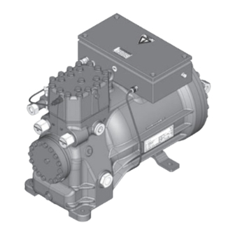
1| Safety 1.4 Intended use These assembly instructions describe the standard version of the HGX2 CO T manufactured by Bock. The compressor is intended for use with CO in transcritical and/or subcritical systems in compliance with the limits of application. Only the refrigerant specified in these instructions may be used. Any other use of the compressor is prohibited! WARNING! The compressor may not be used in potentially explosive environments! The Bock refrigerating compressor named in the title is intended for installing in a machine (within the EU according to the EU Directives 2006/42/EC Machinery Directive, 97/23/EC Pressure Equipment Directive and 2006/95/EC – Low Voltage Directive). - Page 6 2 | Product description 2.1 Short description • Semi-hermetic two-cylinder reciprocating compressor with suction gas-cooled drive motor. • T he refrigerant coming from the evaporator is entering the compressor and flowing over the motor. This ensures an especially intensive cooling of the motor. Therefore the motor temperature remains on a relatively low level - especially at high load. • Cylindrical roller bearing support the crankshaft on the oilpumpside.
-
Page 7: Name Plate
2 | Product description 2.2 Name plate (example) GEA Bock GmbH 72636 Frickenhausen, Germany HGX2/110-4 CO 380-420V Y/YY AS30046A002 9,66 32,3 A 440-480V Y/YY Y Y : 110 A Y: 141 A 11,66 1740 100/150 bar CO2,C 85 E Fig. 3 Voltage, circuit, frequency... -
Page 8: Areas Of Application
3 | Areas of application 3.1 Refrigerants • CO R744 3.2 Oil charge The compressors are filled at the factory with the following oil type: Bock C 85 E (only this oil may be used). ATTENTION! The oil level must be in the visible part of the sight max. oil level glass; damage to the com- min. oil level pressor is possible if over- Fig. 4 filled or underfilled! 3.3 Limits of application... -
Page 9: Compressor Assembly
4 | Compressor assembly INFO! New compressors are factory-filled with inert gas (3 bar nitrogen). Leave this service charge in the compressor for as long as possible and prevent the ingress of air. Immediately after coolingtechnical connection of the compressor of shutoff devices in suction-, discharge-, oil return line etc. close and compressors evacuate. Check the compressor for transport damage before starting any work. -
Page 10: Flange Shut-Off Valves (Hp/Lp)
4 | Compressor assembly 4.3 Flange shut-off valves (HP/LP) ATTENTION! The compressor must be depressurised through connections A and B before commencing any work and prior to connecting to the refrigerant system Fig. 10 Fig. 11 4.4 Operating mode of the lockable service connections Connection cannot Connection be shut off blocked Spindle Service connec- Fig. 12 tion closed Pipe connection Opening the shut-off valve: Spindle: turn to the left (counter-clockwise) as far as it will go. —> Shut-off valve completely opened / service connection closed. The connection which cannot be shut off is intended for safety devices. -
Page 11: Operating The Shut-Off Valves
4 | Compressor assembly 4.5 Operating the shut-off valves Before opening or closing the shut-off valve, release the valve spindle seal by approx. ¼ of a turn counter-clockwise. After activating the shut-off valve, re-tighten the adjustable valve spindle seal clockwise. tighten release Valve spindle seal Fig. 14 Fig. 15 4.6 Pipe connections • The compressor has a shut-off valve with multi-sided cutting ring for the safe installation of the suction and discharge line. Cutting ring function before tightening the union nut Fig. 16 Procedure: Push Union Nut (5) and Cut Ring (3) onto Pipe (2). Hand tighten Union Nut (5) until locked. Insert Pipe (2) firmly into rebate located in Socket (6) ensuring the pipe fits snugly. Tighten Union Nut (5) 1 ½ turns using a spanner/wrench, while gripping connecting Socket (6) with another spanner/wrench. -
Page 12: Information For Contactor And Motor Contactor Selection Dgb
4 | Compressor assembly ATTENTION! Improperly installed pipes can cause cracks and tears which can result in a loss of refrigerant. A rule of thumb: Always lay the first pipe section starting from the shut-off valve downwards and parallel to the drive shaft. Rigid fixed point As short as Fig. 17 possible 5| Electrical connection Electrical connection DANGER! -
Page 13: Standad Motor, Designed For Direct Or Part Winding Start
5 | Electrical connection 5.2 Standard motor, designed for direct or part winding start Designation on the name plate Sticker on the terminal box Y/YY Compressors marked in this way are suitable for direct or part winding start. The motor winding is divided into two parts: part winding 1 = 70% and part winding 2 = 30%. This winding devision redu- ces the start-up current during a part winding start to approx. 65% of the value for a direct start. INFO! Mechanical start unloader with bypass solenoid is not required. In the factory, the motor is switched for direct starting (YY). For part winding start (Y/YY), remove the bridges and connect the motor feed cable according to the circuit diagram. 400 V Direct start YY Part winding start Y/YY ATTENTION! Failure to comply results in reversed fields of rotation and can cause motor damage. After the motor has started up with part win- ding 1, part winding 2 must be switched on after max. 1 second delay. - Page 14 5.3 Basic circuit diagram for part winding start 0 1 2 3 4 F1.2 F1.1 I=33% I=66% F1.1 F1.2 XSS X1 L1 L1 N N 43 43 11 Y/YY X2 1 MP10 Compressor terminal box AnschluastenVerdichter Fig. 18 R1 Cold conductor (PTC sensor) motor winding R2 Thermal protection thermostat (PTC sensor) F1.1 /1.2 2 motor protection switches (70% / 30% of I total) F2 Control power circuit fuse...
- Page 15 5 6 7 8 9 L1.1 L2.1 L3.1 L1.2 P> P< Pl Q1 Main switch M1 Compressor motor K1 Mains contactor (part winding 1) K2 Mains contactor (part winding 2) K1T Delay relay max. 1s S1 Control voltage switch E1 Oil sump heater XSS Terminal strip in the external switch cabinet PWMP10 BKMPRESSRS...
-
Page 16: Electronic Trigger Unit Mp
5 | Electrical connection 5.4 Electronic trigger unit MP 10 The compressor motor is fitted with cold conductor temperature sensors (PTC) connected to the electronic trigger unit MP 10 in the terminal box. Readiness to operate is signalled by the H3 LED (green) after the power supply is applied. In the case of excess temperature in the motor winding, the unit switches off the compressor and the H1 LED lights red. The hot gas side of the compressor can also be protected against overtemperature using a thermal protection thermostat. The H2 LED (red) is provided for the protection function. The unit trips when an overload or inadmissible operating conditions occur. Find and remedy the cause. -
Page 17: Oil Sump Heater (Accessories)
5 | Electrical connection 5.6 Function test of the trigger unit MP 10 Before start-up, troubleshooting or making changes to the control power circuit, check the functionality of the trigger unit: LED H1 LED H2 LED H3 Procedure green • Interrupt power supply (L1 or S1) • Release the motor temperature sensor connection (1 or 2) • Release the hot gas temperature sensor (if installed) (3 or 4) • Restore the power supply (L1 or S1) •... -
Page 18: Commissioning
6 | Commissioning 6.1 Preparations for start-up INFO! In order to protect the compressor against inadmissible operating conditions, high-pressure and low-pressure pressostats controls are mandatory on the installation side. The compressor has undergone trials in the factory and all functions have been tested. There are therefore no special running-in instructions. Check the compressor for transport damage! WARNING! When the compressor is not running, depending on ambient temperature and amount of refrigerant charge, it is possible that the pressure may rise and exceed permitted levels for the compressor. Adequate precautions must be taken to prevent this happening (e.g. using a cold storage medium, a receiver tank, a secondary refrigerant system, or pressure relief devices). -
Page 19: Refrigerant Charge
6 | Commissioning First evacuate the system and then include the compressor in the evacuation process. Relieve the compressor pressure. Open the suction and pressure line shut-off valves. Evacuate the suction and discharge pressure sides using the vacuum pump. At the end of the evacuation process, the vacuum should be < 1.5 mbar when the pump is switched off. Repeat this process as often as is required. 6.5 Refrigerant charge CAUTION! Wear personal protective clothing such as goggles and protective gloves! Make sure that the suction and pressure line shut-off valves are open. INFO! Depending upon design of the CO refrigerant filling bottle (with/without tubing) CO can be filled in liquid after weight or gaseously. -
Page 20: Start-Up
6 | Commissioning 6.6 Start-up WARNING! Ensure that both shut-off valves are open before starting the compressor! Check that the safety and protection devices (pressure switch, motor protection, electrical contact protection measures, etc.) are functioning properly. Switch on the compressor and let it run for at least 10 minutes. The machine should reach a state of equilibrium. Check the oil level: The oil level must be visible in the sight glass. After a compressor is replaced, the oil level must be checked again. If the level is too high, oil must be drained off (danger of oil liquid shocks; reduced capacity of the refrigerating system). ATTENTION! I f larger quantities of oil have to be topped up, there is a risk of oil impact effects. If this is the case, check the oil return! 6.7 Decompression valve The compressor is fitted with two decompression valves. One valve each on the suction and discharge side. If excessive pressures are reached, the valves open and prevent further pressure increase. Thereby CO is blown off to the ambient (see also Chapter 7.6)! In the event that a pressure relief valve activates repeatedly, check valve and replace if necessary as during blow-off extreme conditions can occure, which... - Page 21 6 | Commissioning 6.8 Avoid slugging ATTENTION! Slugging can result in damage to the compressor and cause refrigerant to leak. To prevent slugging: The complete refrigeration plant must be properly designed. All components must be compatibly rated with each other with regard to output (particularly the evaporator and expansion valves). Suction gas superheating at the compressor input should be > 10 K (check the setting of the expansion valve). The system must reach a state of equilibrium. P articularly in critical systems (e.g. several evaporator points), measures such as the use of liquid traps, solenoid valve in the liquid line, etc. are recommended. There should be no movement of refrigerant in the compressor while the system is at a standstill.
-
Page 22: Maintenance
7 | Maintenance 7.1 Preparation WARNING! Before starting any work on the compressor: Switch off the compressor and secure it to prevent a restart. Close all shut-off valves. Relieve compressor of system pressure. Prevent air from infiltrating the system! After maintenance has been performed: Connect safety switch. Evacuate compressor. Open all shut-off valves. Function of the safety devices guarantee. -
Page 23: Decommissioning
7 | Maintenance 7.6 Decommissioning Close the shut-off valves on the compressor. CO does not need to be recycled and can therefore be blown off into the environment. It is essential to ensure good ventilation or conduct the CO into the outdoors to avoid danger of suffocation. When releasing CO , avoid a fast drop in pressure to prevent oil from exiting with it. If the compressor is unpressurized, remove the piping on the pressure- and suction-side (e.g. dismantling of the shut-off valve, etc.) and remove the compressor using an appropriate hoist. Dispose of the oil inside in accordance with the applicable national regulations. When decommissioning the compressor (eg. for service or replacement of the compressor) larger amounts of CO in the oil can be set free. If the decompression of the compressor is not sufficient enough, closed shut-off valves may lead to intolerable excessive pressure. For this reason the suction side (LP) and the high pressure side (HP) of the compressor have to be secured by decompression valves. -
Page 24: Technical Data
8 | Technical data 380-420 V Y/YY - 3 - 50 Hz PW 440-480 V Y/YY - 3 - 60 Hz PW PW=Part Winding Winding ratio: 70%/30%... -
Page 25: Dimensions And Connections
9 | Dimensions and connections Maße Zubehör / Dimensions Maße Zubehör / D Centre of gravity A1 A A1 A Maße Zubehör / Dimensions Accessories / Dimension Accessories ca.675 Schwing Vibratio Amortis ca.240 ca.240 ca.635 ca.635 Änderungen vorbehalten Änderungen vorbehalten ca.300 ca.300 Subject to change without notice Subject to change without ca.345... -
Page 26: Declaration Of Conformity And Installation
DECLARATION OF CONFORMITY CE 07 for using the compressors within the European Union (in accordance with Low Voltage Directive 2006/95/EC) We hereby declare that the following refrigerating compressors Product designation: HGX2 CO comply with the Low Voltage Directive 2006/95/EC. Applied harmonised standard: EN 60034-1, EN 60204-1 DECLARATION OF INSTALLATION for using the compressors within the European Union (in accordance with Machinery Directive 2006/42/EC) The manufacturer: GEA Bock GmbH, Benzstraße 7 72636 Frickenhausen, Tel.: 07022/9454-0 hereby declares that the refrigerating compressor HGX2 CO T complies with the basic require- ments of Appendix II 1B of the Machinery Directive 2006/42/EC. The following harmonised standards have been applied: EN ISO 12100-1 EN ISO 12100-2 EN 12693 EN 349 A partly completed machine may only be put into operation when it has been established that the machine, into which the partly completed machine is to be installed, conforms to the r egulations of the Machinery Directive (2006/42/EC). -
Page 27: Service
11| Service Dear customer, Bock compressors are top-quality, reliable and service-friendly quality products. If you have any questions about installation, operation and accessories, please contact our technical service or specialist wholesaler and/or our representative. The Bock service team can be contacted by phone with a toll-free hotline 00 800 / 800 000 88 or via e-mail: bock@gea.com. Yours faithfully GEA Bock GmbH Benzstraße 7 72636 Frickenhausen Germany We also provide information on the Internet at www.bock.de. For example, under the "Documentation" link you will find: - Technical information - Product information - Product brochures - and much more... - Page 28 • • GEA Group is a global engineering company with multi-billion euro sales and operations in more than 50 countries. Founded in 1881, the company is one of the largest providers of innovative equipment and process technology. GEA Group is listed in the STOXX® Europe 600 index.
Need help?
Do you have a question about the Bock HGX2 CO2 T Series and is the answer not in the manual?
Questions and answers