Sign In
Upload
Download
Table of Contents
Contents
Add to my manuals
Delete from my manuals
Share
URL of this page:
HTML Link:
Bookmark this page
Add
Manual will be automatically added to "My Manuals"
Print this page
×
Bookmark added
×
Added to my manuals
Manuals
Brands
GEA Manuals
Air Compressor
HG7
Assembly instructions manual
GEA HG7 Series Assembly Instructions Manual
Bock compressor
Hide thumbs
Also See for HG7 Series
:
Manual
(8 pages)
1
2
Table Of Contents
3
4
5
6
7
8
9
10
11
12
13
14
15
16
17
18
19
20
21
22
23
24
25
26
27
28
29
30
31
32
page
of
32
Go
/
32
Contents
Table of Contents
Bookmarks
Table of Contents
Table of Contents
Safety
Identification Of Safety Instructions
Qualifications Required Of Personnel
General Safety Instructions
Intended Use
Product Description
Short Description
Name Plate
Type Key
Areas of Application
Refrigerants
Oil Charge
Compressor Assembly
Setting up
Pipe Connections
Connecting the Trigger Unit MP
Functional Test of the Trigger Unit MP
Pipes
Laying Suction and Pressure Lines
Operating the Shut-Off Valves
Operating Mode of the Lockable Service Connections
Information for Contactor and Motor Contactor Selection
Basic Circuit Diagram for Part Winding Start with Standard Motor DGB
Standard Motor, Design for Direct or Partial Winding Start
Special Motor: Design for Direct or Star-Delta Start
Electronic Trigger Unit MP
Oil Sump Heater (Accessories)
Commissioning
Preparations for Start-Up
Pressure Strength Test
Leak Test
Evacuation
Refrigerant Charge
Start-Up
Connection of Oil Level Regulator
Maintenance
Preparation
Work to be Carried out
Spare Parts Recommendation
Accessories
Extract from the Lubricants Table
Decommissioning
Technical Data
Dimensions and Connections
Declaration of Conformity and Installation
Service
Advertisement
Quick Links
1
Spare Parts Recommendation
Download this manual
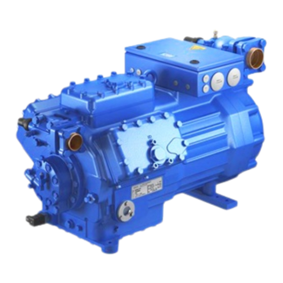
Bock Compressor HG7
Assembly instructions
HG7/1620-4
HG7/1860-4
HG7/2110-4
engineering for a better world
HG7/1620-4 S
HG7/1860-4 S
HG7/2110-4 S
HGX7/1620-4
HGX7/1860-4
HGX7/2110-4
GEA Refrigeration Technologies
HGX7/1620-4 S
HGX7/1860-4 S
HGX7/2110-4 S
1
D
GB
F
E
Table of
Contents
Previous
Page
Next
Page
1
2
3
4
5
Advertisement
Table of Contents
Need help?
Do you have a question about the HG7 Series and is the answer not in the manual?
Ask a question
Questions and answers
Related Manuals for GEA HG7 Series
Air Compressor GEA HG4 Manual
(8 pages)
Air Compressor GEA HG76e/1620-4 Assembly Instructions Manual
(38 pages)
Air Compressor GEA HGX6 R134a series Assembly Instruction Manual
Bock compressor (32 pages)
Air Compressor GEA Bock HGX6/1240-4 R134a Assembly Instructions Manual
(32 pages)
Air Compressor GEA Bock HG44e Series Assembly Instructions Manual
(42 pages)
Air Compressor GEA HG34P/215-4 Assembly Instructions Manual
(30 pages)
Air Compressor GEA HG34e Assembly Instructions Manual
Bock compressor (30 pages)
Air Compressor GEA HG22e/160-4 Assembly Instructions Manual
(32 pages)
Air Compressor GEA Bock HG8 Series Assembly Instructions Manual
(38 pages)
Air Compressor GEA HG8 Series Assembly Instructions Manual
Bock compressor (36 pages)
Air Compressor GEA HG5/725-4 Assembly Instructions Manual
(32 pages)
Air Compressor GEA Bock HGX46/280-4 ML CO2 T Assembly Instructions Manual
(36 pages)
Air Compressor GEA HGX34/130-4 ML CO2 T Assembly Instructions Manual
(46 pages)
Air Compressor GEA GEA Bock HG66e Series Assembly Instructions Manual
(38 pages)
Air Compressor GEA HGX12P CO2 Assembly Instructions Manual
(32 pages)
Air Compressor GEA HGX4 R134a Assembly Instructions Manual
(32 pages)
This manual is also suitable for:
Hg7/1620-4
Hg7/1860-4
Hg7/2110-4
Hg7/1620-4 s
Hg7/1860-4 s
Hg7/2110-4 s
...
Show all
Hgx7/1620-4
Hgx7/1860-4
Hgx7/2110-4
Hgx7/1620-4 s
Hgx7/1860-4 s
Hgx7/2110-4 s
Table of Contents
Print
Rename the bookmark
Delete bookmark?
Delete from my manuals?
Login
Sign In
OR
Sign in with Facebook
Sign in with Google
Upload manual
Upload from disk
Upload from URL


Need help?
Do you have a question about the HG7 Series and is the answer not in the manual?
Questions and answers