
Related Manuals for GEA HGX12P CO2


Summary of Contents for GEA HGX12P CO2
- Page 1 GEA Compressor HGX12P CO Assembly instructions HGX12P/30-4 CO HGX12P/40-4 CO HGX12P/50-4 CO HGX12P/75-4 CO engineering for a better world...
-
Page 2: Table Of Contents
Observe the safety instructions contained in these instructions. These instructions must be passed onto the end customer along with the unit in which the compres- sor is installed. Manufacturer GEA Bock GmbH 72636 Frickenhausen Contact GEA Bock GmbH Benzstraße 7... - Page 3 Contents Page Areas of application 3.1 Refrigerants 3.2 Oil charge 3.3 Limits of application Compressor assembly 4.1 Storage and transport 4.2 Setting up 4.3 Pipe connections 4.4 Pipes 4.5 Laying suction and pressure lines 4.6 Operating the shut-off valves 4.7 Operating mode of the lockable service connections Electrical connection 5.1 Information for contactor and motor contactor selection 5.2 Connection of the driving motor...
-
Page 4: Safety
1| Safety 1.1 Identification of safety instructions: Indicates a dangerous situation which, if not DANGER! avoided, will cause immediate fatal or serious injury. Indicates a dangerous situation which, if not WARNING! avoided, may cause fatal or serious injury. Indicates a dangerous situation which, if not CAUTION! avoided, may cause fairly severe or minor injury. Indicates a situation which, if not ATTENTION! avoided, may cause property damage. INFO! Important information or tips on simplifying work. 1.2 Qualifications required of personnel WARNING! I nadequately qualified personnel poses the risk of accidents, the consequence being serious or fatal injury. Work on compressors must therefore only be performed by personnel with the qualifica- tions listed below: •... -
Page 5: Intended Use
Any other use of the compressor is prohibited! WARNING! The compressor may not be used in potentially explosive environments! The GEA refrigerating compressor named in the title is intended for installing in a machine (within the EU according to the EU Directives 2006/42/EC Machinery Directive, 97/23/EC Pressure Equipment Directive and 2006/95/EC – Low Voltage Directive). -
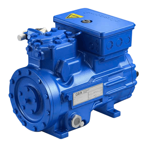
Page 6: Product Description
2| Product description 2.1 Short description • Semi-hermetic two-cylinder reciprocating compressor with oil pump lubrication. • Suction gas cooled drive motor. Transport eyelet Valve plate Name plate Oil pump Oil sight glass Fig. 1 Cylinder cover Terminal box Discharge shut-off valve Drive section Motor section Suction... -
Page 7: Type Key
2| Product description 2.2 Name plate (example) GEA Bock GmbH 72636 Frickenhausen, Germany AS33567A001 40/55 C85E Fig. 3 Type designation Voltage, circuit, frequency 50 Hz Machine number Nominal rotation speed maximum operating current Displacement Starting current (rotor blocked) Voltage, circuit, frequency 60 Hz ND (LP): max. permissible operating... -
Page 8: Areas Of Application
3| Areas of application 3.1 Refrigerants • CO R744 3.2 Oil charge The compressors are filled at the factory with the following oil type: GEA C 85 E (only this oil may be used) The oil level must be in the ATTENTION! max. visible part of the sight glass; damage to the com- oil level 0,5 Ltr. -
Page 9: Compressor Assembly
4| Compressor assembly INFO! New compressors are factory-filled with inert gas (3 bar nitrogen). Leave this service charge in the compressor for as long as possible and prevent the ingress of air. Check the compressor for transport damage before starting any work. 4.1 Storage and transport Storage at (-30°C) - (+70°C), maximum permissible relative humidity 10% - 95%, no condensation Do not store in a corrosive, dusty, vaporous atmosphere or in a com- bustible environment. -
Page 10: Pipes
4| Compressor assembly The pipe connections have graduated inside diameters so that pipes with standart millimetre and inch dimensions can be used. The connection diameters of the shut-off valves are rated for maximum compressor output. The actual required pipe cross section must be matched to the output. -
Page 11: Operating The Shut-Off Valves
4| Compressor assembly 4.6 Operating the shut-off valves Before opening or closing the shut-off valve, release the valve spindle seal by approx. ¼ of a turn counter-clockwise. After activating the shut-off valve, re-tighten the adjustable valve spindle seal clockwise. Tighten Release Valve spindle seal Fig. -
Page 12: Electrical Connection
5| Electrical connection Electrical connection DANGER! R isk of electric shock! High voltage! Only carry out work when the electrical system is disconnected from the power supply! ATTENTION! When attaching accessories with an electrical cable, a minimum bending radius of 3 x the cable diameter must be maintained for laying the cable. INFO! Connect the compressor motor in accordance with the circuit diagram (see inside of terminal box). -
Page 13: Connection Of The Driving Motor
5| Electrical connection 5.2 Connection of the driving motor The compressor is designed with a motor for star-delta circuits. Designation on the name plate Sticker on the terminal box ∆ / Y Star-delta start-up is only possible on 230 V voltage supply. Example: 230 V ∆... - Page 14 5.3 Circuit diagramm for direct start 230 V ∆ / 400 V Y --> compressor with MP10 I> I> I> X1 L1 L1 N N 43 43 11 -EC1 Θ MP10 X2 1 Compressor terminal box Klemmenkasten Verdichter Fig. 17 Cold conductor (PTC sensor) motor winding Thermal protection thermostat (PTC sensor) Load circuit safety switches...
- Page 15 L1.1 L2.1 L3.1 L1.2 A1 Alarm Motorschutz Alarm motor protection Overheating BT1, BT2 A2 Übertemperatur BT1, BT2 P< Alarm high pressure A3 Alarm Hochdruck Main switch Control voltage switch Compressor motor Compressor contactor MP10 Electronic trigger unit MP10 Oil sump heater...
-
Page 16: Electronic Trigger Unit Mp10
5| Electrical connection 5.4 Electronic trigger unit MP 10 The compressor motor is fitted with cold conductor temperature sensors (PTC) connected to the electronic trigger unit MP 10 in the terminal box. Readiness to operate is signalled by the H3 LED (green) after the power supply is applied. - Page 17 5| Electrical connection 5.6 Function test of the trigger unit MP 10 Before start-up, troubleshooting or making changes to the control power circuit, check the functionality of the trigger unit: LED H1 LED H2 LED H3 Procedure green • Interrupt power supply (L1 or SF1) •...
- Page 18 5.7 Circuit diagramm for direct start 230 V ∆ / 400 V Y --> compressor with INT69 G I> I> I> B1 B2 -EC1 INT69 G Θ Compressor terminal box Klemmenkasten Verdichter Fig. 19 Cold conductor (PTC sensor) motor winding Thermal protection thermostat (PTC sensor) Load circuit safety switches Control power circuit fuse...
- Page 19 L1.1 Alarm motor protection A1 Alarm Motorschutz Overheating BT1, BT2 A2 Übertemperatur BT1, BT2 P< Alarm high pressure A3 Alarm Hochdruck Main switch Control voltage switch Compressor motor Compressor contactor INT69 G Electronic trigger unit INT69 G Oil sump heater...
-
Page 20: Electronic Trigger Unit Int69 Ggb
5| Electrical connection 5.8 Electronic trigger unit INT69 G The compressor motor is fitted with cold conductor temperature sensors (PTC) connected to the electronic trigger unit INT69 G in the terminal box. In case of excess temperature in the motor winding, the INT69 G deactivates the motor contactor. - Page 21 5| Electrical connection 5.10 Function test of the trigger unit INT69 G Before commissioning, after troubleshooting or making changes to the control power circuit, check the functionality of the trigger unit. Perform this check using a continuity tester or gauge. Relay position INT69 G Gauge state Relay position...
-
Page 22: Commissioning
6| Commissioning 6.1 Preparations for start-up INFO! In order to protect the compressor against inadmissible operating conditions, high-pressure and low-pressure pressostats controls are mandatory on the installation side. The compressor has undergone trials in the factory and all functions have been tested. There are therefore no special running-in instructions. Check the compressor for transport damage! WARNING! When the compressor is not running, depending on ambient temperature and amount of refrigerant charge, it is possible that... -
Page 23: Refrigerant Charge
6| Commissioning First evacuate the system and then include the compressor in the evacuation process. Relieve the compressor pressure. Open the suction and pressure line shut-off valves. Evacuate the suction and discharge pressure sides using the vacuum pump. At the end of the evacuation process, the vacuum should be < 1.5 mbar when the pump is switched off. Repeat this process as often as is required. -
Page 24: Start-Up
6| Commissioning 6.6 Start-up WARNING! Ensure that both shut-off valves are open before starting the compressor! Check that the safety and protection devices (pressure switch, motor protection, electrical contact protection measures, etc.) are functioning properly. Switch on the compressor and let it run for at least 10 minutes. The machine should reach a state of equilibrium. -
Page 25: Connection Of Oil Level Regulator
6| Commissioning 6.8 Avoid slugging ATTENTION! Slugging can result in damage to the compressor and cause refrigerant to leak. To prevent slugging: The complete refrigeration plant must be properly designed. All components must be compatibly rated with each other with regard to output (particularly the evaporator and expansion valves). -
Page 26: Maintenance
80724 80601 80368 80424 Only use genuine GEA spare parts! 7.4 Accessories Available accessories can be found on the Internet at www.gea.com 7.5 Extract from the lubricants table For operation with CO the oil GEA C 85 E is necessary! -
Page 27: Decommissioning
7| Maintenance 7.6 Decommissioning Close the shut-off valves on the compressor. CO does not need to be recycled and can therefore be blown off into the environment. It is essential to ensure good ventilation or conduct the CO into the outdoors to avoid danger of suffocation. When releasing CO , avoid a fast drop in pressure to prevent oil from exiting with it. -
Page 28: Technical Data
8| Technical data 220-240 V ∆ / 380-420 V Y - 3 - 50 Hz 265-290 V ∆ / 440-480 V Y - 3 - 60 Hz No. of cylinders... -
Page 29: Dimensions And Connections
9| Dimensions and connections ca.240 ca.240 ca.240 SI2,A SI2,A Centre of gravity SI2,A H,D1 H,D1 H,D1 ca.135 ca.135 ca.135 ca.30 ca.415 ca.30 ca.415 ca.30 ca.415 Schwingungsdämpfer Vibration Schwingungsdämpfer Schwingungsdämpfer damper Dimensions in mm Massenschwerpunkt 1) SV 90° drehbar Massenschwerpunkt 1) SV 90° drehbar SV 90°... -
Page 30: Declaration Of Installation
DECLARATION OF INSTALLATION for using the compressors within the European Union (in accordance with Machinery Directive 2006/42/EC) The manufacturer: GEA Bock GmbH, Benzstraße 7 72636 Frickenhausen, Tel.: 07022/9454-0 hereby declares that the refrigerating compressor HGX12P -CO complies with the basic requirements of Appendix II 1B of the Machinery Directive 2006/42/EC. -
Page 31: Service
11| Service Dear customer, GEA compressors are top-quality, reliable and service-friendly quality products. If you have any questions about installation, operation and accessories, please contact our technical service or specialist wholesaler and/or our representative. The GEA service team can be contacted by phone with a toll-free hotline 00 800 / 800 000 88 or via e-mail: refrigeration@gea.com Yours faithfully GEA Bock GmbH Benzstraße 7... - Page 32 • • GEA Group is a global engineering company with multi-billion euro sales and operations in more than 50 countries. Founded in 1881, the company is one of the largest providers of innovative equipment and process technology. GEA Group is listed in the STOXX Europe 600 index.
Need help?
Do you have a question about the HGX12P CO2 and is the answer not in the manual?
Questions and answers