Table of Contents
Advertisement
Quick Links
This user's guide describes the characteristics, operation, and use of the TPS62233EVM-574 evaluation
module (EVM). This EVM demonstrates three individual configurations of the Texas Instruments
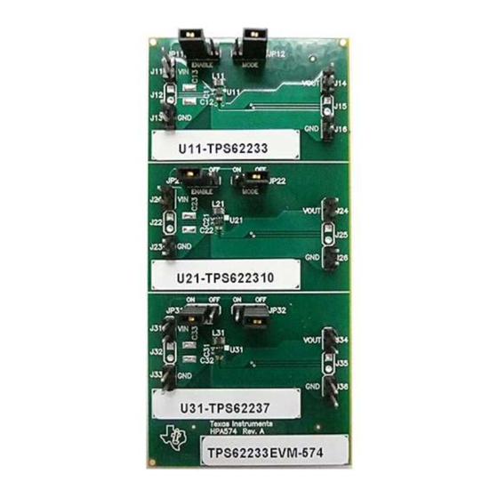
TPS6223x 3-MHz, synchronous step-down converter capable of supplying up to 500 mA of output current.
This user's guide includes setup instructions, a schematic diagram, a bill of materials, and printed-circuit
board layout drawings for the evaluation module.
1
Introduction
.........................................................................................................................
2
Setup
3
4
5
1
2
3
4
1
Device and Output Voltage Configurations
2
3
SLVU360B - April 2010 - Revised July 2013
Submit Documentation Feedback
..................................................................................................................
................................................................................................................
...........................................................................................
.............................................................................................................
..........................................................................................................
......................................................................................................
..................................................................................
............................................................................................
.....................................................................................
Copyright © 2010-2013, Texas Instruments Incorporated
SLVU360B - April 2010 - Revised July 2013
TPS62233EVM-574 User's Guide
Contents
......................................................................
List of Figures
List of Tables
..............................................................................
User's Guide
TPS62233EVM-574 User's Guide
2
2
3
7
8
4
5
6
7
2
3
8
1
Advertisement
Table of Contents

Related Manuals for Texas Instruments TPS62233EVM-574


Summary of Contents for Texas Instruments TPS62233EVM-574
-
Page 1: Table Of Contents
SLVU360B – April 2010 – Revised July 2013 TPS62233EVM-574 User's Guide This user's guide describes the characteristics, operation, and use of the TPS62233EVM-574 evaluation module (EVM). This EVM demonstrates three individual configurations of the Texas Instruments TPS6223x 3-MHz, synchronous step-down converter capable of supplying up to 500 mA of output current. - Page 2 Introduction www.ti.com Introduction The Texas Instruments TPS62233EVM-574 evaluation module helps designers evaluate the operation and performance of the TPS6223x family of devices. These devices are high-efficiency, ultra-small size, buck converters that switch at up to 3 MHz. The EVM contains three independent dc/dc converters.
-
Page 3: Board Layout
Performance is consistent with that shown in the data sheet. Board Layout This section provides the TPS62233EVM-574 board layout and illustrations. SLVU360B – April 2010 – Revised July 2013 TPS62233EVM-574 User's Guide Submit Documentation Feedback Copyright ©... -
Page 4: Assembly Layer
2, and Figure 3 show the board layout for the TPS62233EVM-574 printed-circuit board. The nodes with high- switching frequencies and currents are kept as short as possible to minimize trace inductance. High- impedance inputs to the TPS62233, such as the Vout pin, have traces that are shielded by ground traces and planes. -
Page 5: Top Layer Routing
Board Layout www.ti.com Figure 2. Top Layer Routing SLVU360B – April 2010 – Revised July 2013 TPS62233EVM-574 User's Guide Submit Documentation Feedback Copyright © 2010–2013, Texas Instruments Incorporated... -
Page 6: Bottom Layer Routing
Board Layout www.ti.com Figure 3. Bottom Layer Routing TPS62233EVM-574 User's Guide SLVU360B – April 2010 – Revised July 2013 Submit Documentation Feedback Copyright © 2010–2013, Texas Instruments Incorporated... -
Page 7: Schematic And Bill Of Materials
Schematic and Bill of Materials www.ti.com Schematic and Bill of Materials This section provides the TPS62233EVM-574 schematic and bill of materials. Schematic 1.0 uH 1.0 uH 1.0 uH Figure 4. TPS62233/310/37EVM-574 Schematic SLVU360B – April 2010 – Revised July 2013... -
Page 8: Related Documentation From Texas Instruments
Related Documentation From Texas Instruments www.ti.com Bill of Materials Table 3. TPS62233EVM-574 Bill of Materials Count RefDes Value Description Size Part Number -001 C11,C21,C31 2.2μF Capacitor, Ceramic, 6.3V, X5R, 20% 0402 JMK105BJ225MV-F Taiyo Yuden CL05A225MQ5NNNC Samsung GRM155R60J225ME15D Murata C12,C22,C32 4.7μF Capacitor, Ceramic, 6.3V, X5R, 20%... - Page 9 Any exceptions to this are strictly prohibited and unauthorized by Texas Instruments unless user has obtained appropriate experimental/development licenses from local regulatory authorities, which is responsibility of user including its acceptable authorization.
- Page 10 FCC Interference Statement for Class B EVM devices This equipment has been tested and found to comply with the limits for a Class B digital device, pursuant to part 15 of the FCC Rules. These limits are designed to provide reasonable protection against harmful interference in a residential installation. This equipment generates, uses and can radiate radio frequency energy and, if not installed and used in accordance with the instructions, may cause harmful interference to radio communications.
- Page 11 Also, please do not transfer this product, unless you give the same notice above to the transferee. Please note that if you could not follow the instructions above, you will be subject to penalties of Radio Law of Japan. Texas Instruments Japan Limited (address) 24-1, Nishi-Shinjuku 6 chome, Shinjuku-ku, Tokyo, Japan http://www.tij.co.jp...
- Page 12 FDA Class III or similar classification, then you must specifically notify TI of such intent and enter into a separate Assurance and Indemnity Agreement. Mailing Address: Texas Instruments, Post Office Box 655303, Dallas, Texas 75265 Copyright © 2013, Texas Instruments Incorporated...
- Page 13 IMPORTANT NOTICE Texas Instruments Incorporated and its subsidiaries (TI) reserve the right to make corrections, enhancements, improvements and other changes to its semiconductor products and services per JESD46, latest issue, and to discontinue any product or service per JESD48, latest issue.
Need help?
Do you have a question about the TPS62233EVM-574 and is the answer not in the manual?
Questions and answers