Table of Contents
Advertisement
Quick Links
Compatible with Volvo vehicles with
with 12.3" Touch-Monitor
Video-inserter with 2 video + rear-view camera input
Product features
Video-inserter for factory systems
2 CVBS video-inputs for after-market devices (e.g. DVD-Player, DVB-T tuner, ...)
Rear-view camera CVBS video-input
Automatic switching to rear-view camera input on engagement of the reverse gear
Activatable parking guide lines for rear-view camera (vehicle specific restrictions
possible)
Video-in-motion (ONLY for connected video-sources)
Compatible with factory rear-view camera
Video-inputs NTSC compatible only
Version 13.07.2017
v.LiNK Video-inserter
VL3-SC15
Sensus Connect systems
Advertisement
Table of Contents

Related Manuals for v.link VL3-SC15


Summary of Contents for v.link VL3-SC15
- Page 1 Video-inserter VL3-SC15 Compatible with Volvo vehicles with Sensus Connect systems with 12.3” Touch-Monitor Video-inserter with 2 video + rear-view camera input Product features Video-inserter for factory systems 2 CVBS video-inputs for after-market devices (e.g. DVD-Player, DVB-T tuner, …) ...
-
Page 2: Table Of Contents
Case 2: Video interface does not receive the reverse gear signal 2.5.3.3. Connection Video signal of the rear-view camera 2.6. Connecting video-interface and keypad 2.7. Picture settings and guide lines 3. Interface operation 3.1. By keypad 4. Specifications 5. FAQ – Trouble Shooting-Interface functions 6. Technical support Version 13.07.2017 VL3-SC15... -
Page 3: Prior To Installation
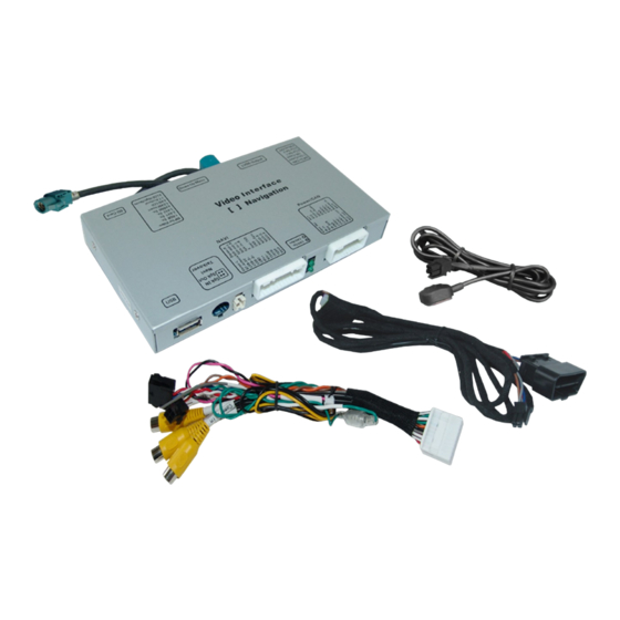
Read the manual prior to installation. Technical knowledge is necessary for installation. The place of installation must be free of moisture and away from heat sources. 1.1. Delivery contents Take down the serial number of the interface and store this manual for support purposes: ____________________ Version 13.07.2017 VL3-SC15... -
Page 4: Checking The Compatibility Of Vehicle And Accessories
The video-interface converts the connected after-market sources video signals into a LVDS signal which is inserted in the factory monitor using separate trigger options and it reads vehicle’s digital signals out of the vehicle’s CAN-bus and converts them for the video interface. Version 13.07.2017 VL3-SC15... -
Page 5: Settings Of The 8 Dip Switches (Black)
Note: Dip 4, 6, 7 and 8 are without function and have to set to OFF. 1.5. Settings of the 4 Dip switches (CAN function - red) Dip position down is ON and position up is OFF. Vehicle/Navigation All vehicles Version 13.07.2017 VL3-SC15... -
Page 6: Installation
The Interface needs a permanent power supply! If power isn’t directly taken from the battery, the connection’s power has to be checked for being start-up proven and permanent. 2.1. Place of installation The interface is installed on the backside of the monitor and at the diagnostic socket. Version 13.07.2017 VL3-SC15... -
Page 7: Connection Schema
Connection schema Version 13.07.2017 VL3-SC15... -
Page 8: Connection To The Monitor
4pin HSD LVDS connector of the interface-box. Connect the waterblue-coloured female 4pin HSD LVDS connector of the 4pin HSD LVDS cable to the blue male 4pin HSD LVDS connector of the factory monitor. Version 13.07.2017 VL3-SC15... -
Page 9: Connection Of Power And Can-Bus
Connect the male diagnostic connector of the CAN harness to the diagnostic socket of the vehicle. Note: Only CAN-High and CAN-Low are connected by the male diagnostic connector of the CAN harness, so we recommend to connect the two cables behind the diagnostic socket in the vehicle. Version 13.07.2017 VL3-SC15... -
Page 10: Connecting Video Sources
Connect the video RCA of the AV-source 1 to the female RCA connector “VideoIN1” of the video cable. Connect the video RCA of the AV-source 2 to the female RCA connector “Video -IN2” of the video cable. Version 13.07.2017 VL3-SC15... -
Page 11: Audio Switch And Audio Insertion
Connect the audio-RCA of the AV-source 1 and the AV source 2 to the female RCA port “AUDIO-IN1” and “AUDIO-IN2” of the audio switch. Connect the audio-RCA of the factory-audio-AUX-input or the FM-modulator to the female RCA port “AUDIO-OUT” of the audio switch. Version 13.07.2017 VL3-SC15... -
Page 12: After-Market Rear-View Camera
The 12 V power supply for the rear-view camera (max 3A) has to be taken from the green wire of the 20pin cable to avoid an unnecessary permanent power supply to the camera electronic. For the operation, both green cables “Reverse-IN” and “Reverse-OUT” have to stay connected. Version 13.07.2017 VL3-SC15... -
Page 13: Case 2: Video Interface Does Not Receive The Reverse Gear Signal
(86) of the relay. Connect the output connector (87) of the relay to the rear-view camera’s power- cable, like you did it to the green “Reverse-IN” cable before. Connect permanent power / 12V to the relay’s input connector (30). Version 13.07.2017 VL3-SC15... -
Page 14: Connecting Video-Interface And Keypad
Video signal connection for the rear-view camera Connect the video-RCA of the after-market rear-view camera to the female RCA port “Camera-IN” of the video-cable. 2.6. Connecting video-interface and keypad Connect the keypad’s female 4pin connector to the video-interface’s male 4pin connector. Version 13.07.2017 VL3-SC15... -
Page 15: Picture Settings And Guide Lines
IR-AV1 (out of function) IR-AV2 (out of function) Guide-lines left Guide-lines right Guide-CNTRL (guide lines ON/OFF) PDC-H-POS (out of function) AV1/2-MAIN (out of function) Note: If the CAN-box does not support the vehicle, the guide-lines cannot be used. Version 13.07.2017 VL3-SC15... -
Page 16: Interface Operation
Power 0.4A @12V Video input 0.5V – 2V Video input formats NTSC RGB-video amplitude 0.5V with 75 Ohm impedance Temperature range -40°C to +85°C Dimensions Video-Box 158 x 23 x 91 mm (W x H x D) Version 13.07.2017 VL3-SC15... -
Page 17: Faq - Trouble Shooting-Interface Functions
Camera is being tested under Camera input picture fluorescent light which shines Test camera under natural light outside the garage. flickers. directly into the camera. Camera input picture is Protection sticker not Remove protection sticker. bluish. removed from camera lens. Version 13.07.2017 VL3-SC15... -
Page 18: Technical Support
6pin to 8pin cable and isolate both ends. Technical Support Please note that direct technical support is only available for products purchased directly. For products bought from other sources, contact your vendor for technical support. 10R-03 5384 Made in China Version 13.07.2017 VL3-SC15...
Need help?
Do you have a question about the VL3-SC15 and is the answer not in the manual?
Questions and answers