Table of Contents
Advertisement
Quick Links
Video-inserter with 2 video + RGB + rear-view camera input and CAN control
Product features
Video-inserter for factory-navigation systems
2 video-inputs for after-market devices (e.g. DVD-Player, DVB-T tuner, ...)
Built-in audio-switch (no audio-insertion)
Rear-view camera video-input
Automatic switching to rear-view camera input on engagement of the reverse gear
Activatable parking guide lines for rear-view camera (vehicle specific restrictions
possible)
RGB-input for after-market navigation
Video-in-motion (ONLY for connected video-sources)
Compatible with factory rear-view camera
Video-inputs PAL/NTSC compatible
Version 29.03.2017
v.LiNK Video-inserter
VL2-FORD-02
For Ford vehicles with
Sync2 System
with 8" touch monitor
Advertisement
Table of Contents

Related Manuals for v.link VL2-FORD-02


Summary of Contents for v.link VL2-FORD-02
- Page 1 Video-inserter VL2-FORD-02 For Ford vehicles with Sync2 System with 8” touch monitor Video-inserter with 2 video + RGB + rear-view camera input and CAN control Product features Video-inserter for factory-navigation systems 2 video-inputs for after-market devices (e.g. DVD-Player, DVB-T tuner, …) ...
-
Page 2: Table Of Contents
Case 2: CAN-box does not receive the reverse gear signal 2.6.4.3. Connection Video signal 2.7. Connecting video-interface and keypad 2.8. Picture settings and guide lines 3. Interface operation 3.1. By Voice button 3.2. By keypad 4. Specifications 5. FAQ – Trouble Shooting-Interface functions 6. Technical support Version 29.03.2017 VL2-FORD-02... -
Page 3: Prior To Installation
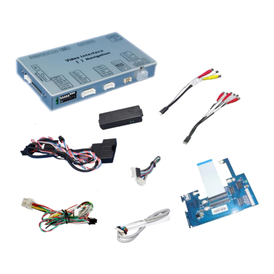
Read the manual prior to installation. Technical knowledge is necessary for installation. The place of installation must be free of moisture and away from heat sources. 1.1. Delivery contents Take down the serial number of the interface and store this manual for support purposes: ____________________ Version 29.03.2017 VL2-FORD-02... -
Page 4: Checking The Compatibility Of Vehicle And Accessories
To delay the switch-back, an additional electronic part is required. 1.3. Boxes and connectors 1.3.1. Video Interface The video-interface converts the connected after-market sources video signals into a LVDS signal which is inserted in the factory monitor using separate trigger options. Version 29.03.2017 VL2-FORD-02... -
Page 5: Can-Bus Box
Only the enabled video inputs can be accessed by switching through the interface’s video sources. It is recommended to enable only the required inputs, because the disabled inputs will be skipped while switching through the video interfaces inputs. Version 29.03.2017 VL2-FORD-02... -
Page 6: Rgb-Video Input Signal Selection For After-Market Navigation (Dip 4)
Dip position down is ON and position up is OFF. If the CAN-Bus communication doesn`t succeed, change the position of dip switch 4 and make a power reset before checking. After each Dip-switch-change a power-reset of the Can-box has to be performed! Version 29.03.2017 VL2-FORD-02... -
Page 7: Installation
2.1.1. Place of installation for the interface-box The interface is built to be connected behind the vehicle`s monitor and head-unit. 2.1.2. Place of installation for the daughter PCB The interface’s daughter PCB is built to be installed in the monitor housing. Version 29.03.2017 VL2-FORD-02... -
Page 8: Connection Schema
2.2. Connection schema Version 29.03.2017 VL2-FORD-02... -
Page 9: Connecting Video-Interface And Can-Box
Note: Check the LEDs on the video-interface after reconnecting the battery, one must be on. Note: No liability for vehicle wire colours and pin definition! Changes by the vehicle manufacturer are possible. The given information has to be verified by the installer. Version 29.03.2017 VL2-FORD-02... -
Page 10: Connection To The Vehicle's Head Unit
Disconnect the female 24pin connector of the vehicle harness from the vehicle’s head-unit and connect it to the male 24pin connector of the PNP Power/CAN cable Connect the female 24pin connector of the PNP Power/CAN cable to the male 24pin connector of the vehicle’s head-unit. Version 29.03.2017 VL2-FORD-02... -
Page 11: Connection To The Vehicle's Monitor
20pin connector (Box Side) opposite the cable to the female 20pin connector of the video interface. Take care for installing the cable in the right direction as both connectors are identical. (Pay attention to the wire`s caption “MONITOR SIDE” and “BOX SIDE”) Version 29.03.2017 VL2-FORD-02... -
Page 12: Warning Notes, Concerning The Installation Of Ribbon Cables
Connect the RGB cable’s female 8pin connector to the video-interface's male 8pin connector. The disconnected grey wires don’t have any function and have to be isolated. Connect the RGB cable’s male 6pin connector to the after-Market navigation. Version 29.03.2017 VL2-FORD-02... -
Page 13: Video-Sources To Av1 And Av2
Connect the video cable’s female 6pin connector to the video interface’s male 6pin connector . Connect of the AV-source 1’s video RCA to the video cable’s female RCA connector Video IN 1. Connect the AV-source 2’s video RCA to the video cable’s female RCA connector Video IN2. Version 29.03.2017 VL2-FORD-02... -
Page 14: Audio-Switch And Audio-Insertion
RCA port AV-Out of the audio cable. Connect the audio-RCA of the AV-source 1 to the female RCA port AV1 of the audio cable. Connect the audio-RCA of the AV-source 2 to the female RCA port AV2 of the audio cable. Version 29.03.2017 VL2-FORD-02... -
Page 15: After-Market Rear-View Camera
CAM while the reverse gear is engaged. Additionally, the +12V (max. 500mA) power supply for the rear-view camera can be taken from the green wire of the 6pin to 12pin cable. Version 29.03.2017 VL2-FORD-02... -
Page 16: Case 2: Can-Box Does Not Receive The Reverse Gear Signal
Connect the reverse gear light signal/power to coil (85) and ground to coil (86) of relay. Connect the rear-view camera power wire and the green wire (video interface side) of 6pin to 8pin cable both to output (87) of the relay. Connect permanent battery power to input (30) of relay. Version 29.03.2017 VL2-FORD-02... -
Page 17: Connecting Video-Interface And Keypad
CAM. Note: The picture settings for CAM input have to be adjusted in AV2. 2.7. Connecting video-interface and keypad Connect the female 4pin connector of the keypad to the male 4pin connector of the video-interface. Version 29.03.2017 VL2-FORD-02... -
Page 18: Picture Settings And Guide Lines
Note: If there is no communication between the CAN box and the vehicle`s CAN-bus (several vehicles aren’t compatible), the .reverse gear guide-lines can`t be shown during the vehicle’s operation, even if they once appear after having switched the system to powerless! Version 29.03.2017 VL2-FORD-02... -
Page 19: Interface Operation
4. Specifications BATT/ACC range 7V - 25V Stand-by power drain <10mA Power 0.7A @12V Power consumption 280mA Video input 0.7V - 1V Video input formats PAL/NTSC RGB-video amplitude 0.7V with 75 Ohm impedance Temperature range -40°C to +85°C Version 29.03.2017 VL2-FORD-02... -
Page 20: Faq - Trouble Shooting-Interface Functions
Camera is being tested under Camera input picture fluorescent light which shines Test camera under natural light outside the garage. flickers. directly into the camera. Camera input picture is Protection sticker not Remove protection sticker. bluish. removed from camera lens. Version 29.03.2017 VL2-FORD-02... -
Page 21: Technical Support
Please note that direct technical support is only available for products purchased directly from NavLinkz GmbH. For products bought from other sources, contact your vendor for technical support. NavLinkz GmbH distribution/tech dealer-support Eurotec-Ring 39 D-47445 Moers +49 2841 949970 Email mail@navlinkz.de 10R-03 5384 Made in China Version 29.03.2017 VL2-FORD-02...
Need help?
Do you have a question about the VL2-FORD-02 and is the answer not in the manual?
Questions and answers