Table of Contents
Advertisement
Quick Links
Business/Professional CIC-E and CIC-F series
navigation systems or radios with colour display
and 4pin HSD LVDS monitor plug
Video-inserter with 2 video + RGB + rear-view camera input
Product features
• Video-inserter for factory-infotainment monitors
• 2 video-inputs for after-market devices (e.g. DVD-Player, DVB-T tuner, ...)
• Built-in audio-switch (no audio-insertion)
• Rear-view camera video-input
• Automatic switching to rear-view camera input on engagement of reverse gear
• RGB-input for after-market navigation
• Video-in-motion (ONLY for connected video-sources)
• Compatible with factory rear-view camera
• AV-inputs PAL/NTSC compatible
• Ultra-wide picture mode 24:9 (only with ultra-wide screens 8.8" and 10.2")
Version 10.02.2014
v.LiNK Video-inserter
VL2-CIC
for BMW vehicles with
Advertisement
Table of Contents

Related Manuals for v.link VL2-CIC


Summary of Contents for v.link VL2-CIC
- Page 1 Video-inserter VL2-CIC for BMW vehicles with Business/Professional CIC-E and CIC-F series navigation systems or radios with colour display and 4pin HSD LVDS monitor plug Video-inserter with 2 video + RGB + rear-view camera input Product features • Video-inserter for factory-infotainment monitors •...
-
Page 2: Table Of Contents
Video-sources to IN1 and IN2 2.5.2. Audio-switch and audio-insertion 2.5.3. After-market rear-view camera 2.5.4. After-market navigation 2.6. Connecting video-interface and keypad 2.7. Picture settings 3. Interface operation 3.1. By iDrive-buttons 4. Specifications 5. Connections (video-interface) 6. Technical support Version 10.02.2014 VL2-CIC... -
Page 3: Prior To Installation
Technical knowledge is necessary for installation. The place of installation must be free of moisture and away from heat sources. 1.1. Delivery contents Take down the serial number of the interface and store this manual for support purposes: ____________________ Version 10.02.2014 VL2-CIC... -
Page 4: Checking The Compatibility Of Vehicle And Accessories
Factory-OPS-display While reverse gear is engaged ONLY the picture of the with after-market rear-cam after-market rear-view camera is visible! (Interface model VL2-CIC-F can display factory OPS and after-market rear-view camera picture simultaneously.) 1.3. Dip-switch settings With the video interface boxes dip-switches it is possible to select vehicle/navigation the... -
Page 5: Video Signal Selection After-Market Navigation(Dip 4)
6pin to 8pin cable at the black 8pin connector and connect it to the reverse gear light (+12V). For this use a relay because the reverse gear light of the vehicle is clocked (relay AC-RW1230 and AC-RS5 optional available). Version 10.02.2014 VL2-CIC... -
Page 6: Installation
If power source is not taken directly from the battery, the connection has to be checked for being start-up proven and permanent. 2.1. Place of installation The interface is installed on the backside of factory monitor. Version 10.02.2014 VL2-CIC... -
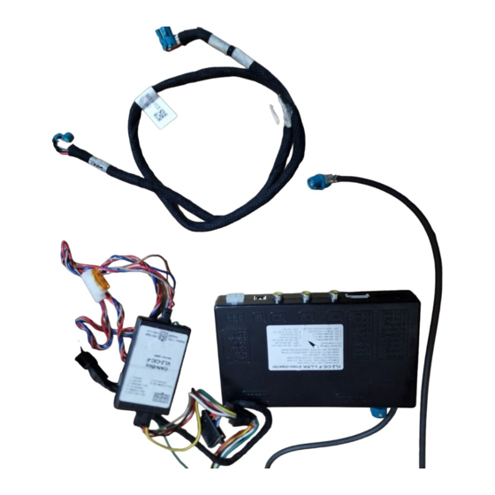
Page 7: Connection Schema
2.2. Connection schema Version 10.02.2014 VL2-CIC... -
Page 8: Connecting Video-Interface And Can-Box
6pin Molex connector of the video-interface. Connect black female 8pin Micro-Fit connector of the 6pin to 8pin cable to male 8pin Micro-Fit connector of the CAN-box. Note: Check LEDs on video-interface after reconnecting the battery, one must be on. Version 10.02.2014 VL2-CIC... -
Page 9: Connection To The Factory Monitor
Before final installation of the peripheral devices, we recommend a test-run to detect incompatibility of vehicle and interface. Due to changes in the production of the vehicle manufacturer is always the possibility of incompatibility. Version 10.02.2014 VL2-CIC... -
Page 10: Video-Sources To In1 And In2
It is possible to switch the audio signals from the to IN1 and IN2 connected AV-sources parallel to the video-signal of the respective AV-source by video-interface’s built-in audio- switch. Version 10.02.2014 VL2-CIC... - Page 11 Audio input signal R/L of source IN1 Audio output signal R/L of factory audio AUX or FM-modulator Ground No function Note: When switching the video interface from video-IN1 to video-IN2, the audio will also automatically be switched. Version 10.02.2014 VL2-CIC...
-
Page 12: After-Market Rear-View Camera
(relay AC-RW1230 and AC-RS5 optional available). Note: Set Dip 5 to ON. Long press OPTION-button or long push iDrive up to switch the picture format: • 16:9 • 24:9 Note: Picture format 24:9 is only available for ultra-wide screens 8.8”/10.2” Version 10.02.2014 VL2-CIC... -
Page 13: After-Market Navigation
The loose grey wires have no function and have to be isolated. Connect male 6pin connector of the RGB cable to the after-Market navigation. 2.6. Connecting video-interface and keypad Connect the female 4pin connector of the keypad to the male 4pin connector of the video-interface. Version 10.02.2014 VL2-CIC... -
Page 14: Picture Settings
Press CD- or RADIO-button to return to the factory-video. Long press OPTION-button or long push iDrive up to switch the picture format: • 16:9 • 24:9 Note: Picture format 24:9 is only available for ultra-wide screens 8.8”/10.2” Version 10.02.2014 VL2-CIC... -
Page 15: Specifications
Video input 0.7V~1V Video input formats PAL/NTSC RGB-video amplitude 0.7V with 75 Ohm impedance Temperature range -40°C to +85°C Weight 195g Dimensions (box only) B x H x T 182 x 24 x 100 mm 5. Connections (video-interface) Version 10.02.2014 VL2-CIC...
Need help?
Do you have a question about the VL2-CIC and is the answer not in the manual?
Questions and answers