Table of Contents
Advertisement
Quick Links
Firmware: v.5.18 or higher
•
Input type: TC K/S/J/T/N/R/B/E
•
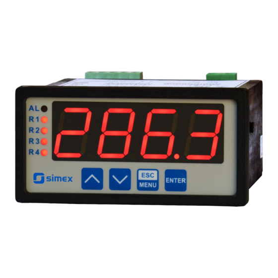
4 x 20 mm display
•
Read the user's manual carefully before starting to use the unit or software.
Producer reserves the right to implement changes without prior notice.
2018.12.20
User manual
METER
SRT-94-XA
Assisting the automation
industry since 1986
SRT-94-XA_INSSXEN_v.2.11.001
Advertisement
Table of Contents

Related Manuals for Simex SRT-94-XA


Summary of Contents for Simex SRT-94-XA
- Page 1 Assisting the automation industry since 1986 User manual METER SRT-94-XA Firmware: v.5.18 or higher • Input type: TC K/S/J/T/N/R/B/E • 4 x 20 mm display • Read the user's manual carefully before starting to use the unit or software. Producer reserves the right to implement changes without prior notice.
-
Page 2: Table Of Contents
User manual - METER SRT-94-XA CONTENTS 1. BASIC REQUIREMENTS AND USER SAFETY..................3 2. GENERAL CHARACTERISTICS........................4 3. TECHNICAL DATA............................4 4. DEVICE INSTALLATION..........................6 4.1. UNPACKING............................6 4.2. ASSEMBLY............................7 4.3. CONNECTION METHOD........................9 4.4. MAINTENANCE..........................13 5. FRONT PANEL DESCRIPTION........................14 6. PRINCIPLE OF OPERATION........................14 6.1. MEASUREMENT MODE........................14... -
Page 3: Basic Requirements And User Safety
User manual - METER SRT-94-XA Explanation of symbols used in the manual: - This symbol denotes especially important guidelines concerning the installation and operation of the device. Not complying with the guidelines denoted by this symbol may cause an accident, damage or equipment destruction. -
Page 4: General Characteristics
2. GENERAL CHARACTERISTICS The SRT-94-XA meter is equipped with thermocouple input (K, S, J, T, N, R, B, E). The measurement range depends on connected thermocouple type. Measurement is linearised by the polynomial characteristics referred to particular thermocouples and temperature of cold ends is compensated automatically. - Page 5 User manual - METER SRT-94-XA Measurement range -200˚C ÷ +1370˚C -50˚C ÷ +1768˚C -210˚C ÷ +1200˚C -200˚C ÷ + 400˚C -200˚C ÷ +1300˚C -50˚C ÷ +1768˚C +250˚C ÷ +1820˚C -200˚C ÷ +1000˚C Voltage: -10mV ÷ 90mV Measurement accuracy ± 0,1% @ 25°C; ± one digit Accuracy of cold ends temperature ±...
-
Page 6: Device Installation
User manual - METER SRT-94-XA Safety requirements according to: PN-EN 61010-1 installation category: II pollution degree: 2 voltage in relation to ground: 300V AC insulation resistance: >20MW insulation strength between power supply and input/output terminal: 1min. @ 2300V insulation strength between relays terminal: 1min. -
Page 7: Assembly
User manual - METER SRT-94-XA 4.2. ASSEMBLY - The unit is designed for mounting inside housings (control panel, switchboard) insuring appropriate protection against surges and interference. Metal housings must be connected to ground in a way that complies with the governing regulations. - Page 8 User manual - METER SRT-94-XA 92 mm max. 5 mm Figure 4.2. Allowable mounting hole dimensions 92 mm 5 mm 12 mm 10 mm Figure 4.3. Installing of brackets, and dimensions of connectors. 115 mm Figure 4.4. Minimum distances when assembly of a number of units...
-
Page 9: Connection Method
User manual - METER SRT-94-XA 4.3. CONNECTION METHOD Caution - Installation should be conducted by qualified personnel . During installation all available safety requirements should be considered. The fitter is responsible for executing the installation according to this manual, local safety and EMC regulations. - Page 10 User manual - METER SRT-94-XA – Use of screened signal cables is recommended. Signal cable screens should be connected to the earthing only at one of the ends of the screened cable. – In the case of magnetically induced interference the use of twisted pair of signal cables is recommended.
- Page 11 User manual - METER SRT-94-XA RS - 485 Power +24V +5%, -10% supply optional ACTIVE DATA+ max = 100mA current output (depending on version) DATA- (optional) 5 6 7 8 9 10 11 12 13 14 15 GND GND n.c. n.c.
- Page 12 User manual - METER SRT-94-XA 10 11 10 11 Figure 4.9. Examples of suppression circuit connection: a) to relay terminals; b) to the inductive load 10 11 12 13 14 15 FUSE FUSE Depending on version: 85...230...260V AC/DC or 19...24...50V DC; 16...24...35V AC...
-
Page 13: Maintenance
User manual - METER SRT-94-XA 10 11 10 11 Logic controller LED 10 mA voltage input 24 V Figure 4.11. Example of OC-type outputs connection optional ACTIVE current output Logic controller current input 4-20 mA Figure 4.12. Example of current outputs connection (for device with current output only) 4.4. -
Page 14: Front Panel Description
User manual - METER SRT-94-XA 5. FRONT PANEL DESCRIPTION display alarm LED indicator (AL) Thresholds exceeding LED indicators (R) ENTER MENU programming pushbuttons Symbols and functions of push-buttons: Symbol used in the manual: [ESC/MENU] Functions: MENU • Enter to main menu ( press and hold by at least 2 sec.) •... -
Page 15: Detection Of The Peak Values
Configuration of the device (via menu or RS-485 interface) do not stops measures . 6.2. DETECTION OF THE PEAK VALUES The SRT-94-XA controller is equipped with peaks detection function. It can detect a peaks of the input signal and display their values. Presets connected with this function are placed in ”HOLd”... - Page 16 User manual - METER SRT-94-XA Modes of the control can be changed depend on the values of parameters “SEtP” , “SEt2”, “HYSt”, “modE”, “t on”, “toFF”, “unit” and “AL”. Depend on “modE” parameter, relays can be not used or controlled over one or two thresholds values.
-
Page 17: One Threshold Mode
User manual - METER SRT-94-XA 6.3.1. One threshold mode Figure 6.4 presents the principle of relay outputs operation for one threshold mode, and an example values of other parameters. measured “SEtP” parameter displayed value signal (expected signal value) zone A “HYSt”... -
Page 18: Two Thresholds Mode
User manual - METER SRT-94-XA (when input signal stay in zone A or zone B) are lower than parameters “t on” If t or t or “toFF”, the relay will not change his state (see points A and C, Figure 6.4 a, d, e). -
Page 19: Device Programming
User manual - METER SRT-94-XA Figure 6.5 presents the principle of relay outputs operation for two thresholds mode, and an example values of other parameters. In this mode parameter “SEt2” is accessible in common with “SEtP” , this parameter describes a second threshold of the relay output. The parameters “HYSt”, “modE”, “t on”, “toFF”, “unit”... -
Page 20: Parameters Edition
User manual - METER SRT-94-XA Functions of the buttons while sub-menu and parameters choice: Selection of sub-menu or parameter for editing. Name of selected item (sub- menu or parameter) is displayed. Operation of [ENTER] button depend on present menu position: ENTER •... -
Page 21: Switch Parameters ("List" Type)
User manual - METER SRT-94-XA down and will be kept on lower speed. Press [ENTER] at least 2 seconds to accept the changes, after that question ”Set?” is displayed, and user must to confirm (or cancel) the changes. To conform changes (and story it in EEPROM) press [ENTER] button shortly after ”SEt?”... -
Page 22: Rel1" Menu
User manual - METER SRT-94-XA 7.3.1. “rEL1” menu This menu allows to configure the operation mode of relays and LEDs marked „ R ” (e.g. „ R1 ”). If there are few relay outputs available, then every output has its own configuration menu (e.g. - Page 23 User manual - METER SRT-94-XA - two threshold mode, relay is turned ON when the input value is bigger “out” than “bigger threshold + HYSt” and lower than “lower threshold – HYSt” , and turned on when the input signal is contained in the second zone.
-
Page 24: Beep" Menu
User manual - METER SRT-94-XA If parameter „ AL ” = „ on ”, the relay will be turned on in the critical situations, • even if his parameter “modE” = ”noAC”. 7.3.2. “bEEP” menu This menu contains options connected with acoustic signal : "... -
Page 25: Outp" Menu
User manual - METER SRT-94-XA 7.3.4. ”OutP” menu This menu contains parameters of current output control. Menu is available if the device is equipped witch current output. Current output can be controlled depend on both present measured value and peak value (if peak detection is enabled). -
Page 26: Bri" Parameter
User manual - METER SRT-94-XA “AL” - this parameter determines the behaviour of current output if any critical situation occurs. The parameter can be set to one of the values: “noCH” - current will not change, “22.1” - current will be set to 22.1 mA, “3.4”... -
Page 27: Secu" Menu
User manual - METER SRT-94-XA 7.3.7. ”SECu” menu This menu contains presets connected with availability of other parameters: “Scod” - user password (4-digits number). If this parameter is set at value “0000” , user password is turned off. If the user do not remember his password, the access to the menu is possible by the “one-use password”. -
Page 28: Edit" Parameter
User manual - METER SRT-94-XA works properly on baud rates higher than 19200. This parameter can be set to one of values: ”Std” - answer as quick as possible, no additional delay ” 10c” ” 20c” - answer delayed of 10, 20, 50, 100 of 200 chars respectively, where ”... -
Page 29: Menu Structure
User manual - METER SRT-94-XA 7.4. MENU STRUCTURE Measurement mode Press and hold at least 2 seconds MENU MENU 4-digit user password entering (if it is different from „0000”) 0 _ _ _ ENTER ENTER ENTER Parameter MENU rEL1 SEtP... - Page 30 User manual - METER SRT-94-XA See previous page ENTER ENTER Parameter MENU modE HOLd edition ENTER MENU timE Hdis MENU H r1 H r2 H r3 H r4 HOUt ENTER ENTER Parameter MENU SECu Scod edition ENTER MENU A r1...
-
Page 31: The Alarm Led
User manual - METER SRT-94-XA 8. THE ALARM LED Alarm LED (AL) lights in cases: • exceeding of permissible measurement range • detection of sensor malfunction (break of measurement circuit) 9. CURRENT OUTPUT VALUE CALCULATION Let the current output parameters be: “modE”... - Page 32 User manual - METER SRT-94-XA Register Write Range Register description Measurement value (no decimal point) easurement range The status of the current measurement; 0h - data valid; A0h - 0h, A0h, 60h top border of the measurement range is exceeded; 60h - bottom border of the measurement range is exceeded;...
- Page 33 User manual - METER SRT-94-XA Register Write Range Register description “rESP” parameter in “rS” menu (additional response delay); 0 ÷ 5 0 - no additional delay; 1 - ”10c” option; 2 - ”20c” option; 3 - ”50c” option; 4 - ”100c” option; 5 - ”200c” option;...
- Page 34 User manual - METER SRT-94-XA Register Write Range Register description “toFF” parameter in “rEL2” menu, expressed in tenth of 0 ÷ 999 seconds or tenth of minutes depend on “unit” parameter - register no. 3Dh) “unit” parameter in “rEL2” menu: 0 ÷...
- Page 35 User manual - METER SRT-94-XA Register Write Range Register description “modE” parameter in “HOLd” menu (type of detected 0 ÷ 1 changes): 0 - peaks; 1 - drops “PEA” parameter in “HOLd” menu (minimum detectable 0 ÷ 9999 change, no decimal point included) “timE”...
-
Page 36: Transmission Errors Description
Data byte count in answer frame DATA H,L Data byte (Hi and Lo byte) CRC L,H CRC error check (Hi and Lo byte) 1. Read of the displayed value (measurement), SRT-94-XA device address = 01h: ADDR FUNC REG H,L COUNT H,L... - Page 37 User manual - METER SRT-94-XA ERROR - error code = 60h, bottom border of the measurement range is exceeded 2. Read of device ID code ADDR FUNC REG H,L COUNT H,L CRC L,H The answer: ADDR FUNC BYTE C DATA H,L...
- Page 38 User manual - METER SRT-94-XA 5. Read of the registers 1, 2 and 3 in one message (example of reading a number of registries in one frame): ADDR FUNC REG H,L COUNT H,L CRC L,H COUNT L - the count of being read registers (max.16)
-
Page 39: Default And User's Settings List
User manual - METER SRT-94-XA 11. DEFAULT AND USER'S SETTINGS LIST Desc. Parameter Description Default value User's value page Parameters of relay R1 operation (“rEL1” menu) SEtP Relay R1 threshold 20.0 SEt2 Relay R1 second threshold 40.0 HYSt Hysteresis of relay R1... - Page 40 User manual - METER SRT-94-XA Desc. Parameter Description Default value User's value page t on Turn on delay of relay R4 toFF Turn off delay of relay R4 unit Unit of “t on”, “toFF” parameters of relay R4 Reaction for critical situation of relay R4 Activation of acoustic signal (menu “bEEP”)
- Page 41 User manual - METER SRT-94-XA Desc. Parameter Description Default value User's value page Settings of access to the configuration parameters (“SECu” menu) Permission to changes of relay R1 threshold A r1 without of the user password knowledge Permission to changes of relay R2 threshold...
- Page 42 User manual - METER SRT-94-XA...
- Page 43 User manual - METER SRT-94-XA...
- Page 44 SIMEX Sp. z o.o. ul. Wielopole 11 80-556 Gdańsk Poland tel.: (+48 58) 762-07-77 fax: (+48 58) 762-07-70 http://www.simex.pl e-mail: info@simex.pl...
Need help?
Do you have a question about the SRT-94-XA and is the answer not in the manual?
Questions and answers