Table of Contents
Advertisement
Quick Links
Firmware: v.6.00 or higher
•
Input type: TC K/S/J/T/N/R/B/E
•
Wall mounting case IP 67
•
Read the user's manual carefully before starting to use the unit or software.
Producer reserves the right to implement changes without prior notice.
2014.12.31
User manual
METER
SRT-N118-XA
Assisting the automation
industry since 1986
SRT-N118-XA_INSSXEN_v.2.09.004
Advertisement
Table of Contents

Related Manuals for Simex SRT-N118-XA


Summary of Contents for Simex SRT-N118-XA
- Page 1 Assisting the automation industry since 1986 User manual METER SRT-N118-XA Firmware: v.6.00 or higher • Input type: TC K/S/J/T/N/R/B/E • Wall mounting case IP 67 • Read the user's manual carefully before starting to use the unit or software. Producer reserves the right to implement changes without prior notice.
-
Page 2: Table Of Contents
User manual - METER SRT-N118-XA CONTENTS 1. BASIC REQUIREMENTS AND USER SAFETY..................3 2. GENERAL CHARACTERISTICS........................4 3. TECHNICAL DATA............................5 4. DEVICE INSTALLATION..........................7 4.1. UNPACKING............................7 4.2. ASSEMBLY............................8 4.3. CONNECTION METHOD........................8 4.4. MAINTENANCE..........................16 5. FRONT PANEL DESCRIPTION........................17 6. PRINCIPLE OF OPERATION........................17 6.1. MEASUREMENT MODE........................17... -
Page 3: Basic Requirements And User Safety
User manual - METER SRT-N118-XA Explanation of symbols used in the manual: - This symbol denotes especially important guidelines concerning the installation and operation of the device. Not complying with the guidelines denoted by this symbol may cause an accident, damage or equipment destruction. -
Page 4: General Characteristics
2. GENERAL CHARACTERISTICS The SRT-N118-XA meter is equipped with thermocouple input (K, S, J, T, N, R, B, E). The measurement range depends on connected thermocouple type. Measurement is linearised by the polynomial... -
Page 5: Technical Data
User manual - METER SRT-N118-XA 3. TECHNICAL DATA Power supply voltage 85... 230 ...260V AC/DC; 50 ÷ 60 Hz (separated) (depending on version) or 19...24...50V DC and 16...24...35V AC (separated) External fuse (required) T - type, max. 2 A Power consumption max. - Page 6 User manual - METER SRT-N118-XA range max. 0 ÷ 24 mA Active current output (optional, for one relay or one OC-type output version only) Load resistance max. 700 Ω range max. 2.8 ÷ 24 mA Passive isolated current output (optional, for one relay or one...
-
Page 7: Device Installation
User manual - METER SRT-N118-XA Safety requirements according to: PN-EN 61010-1 installation category: II pollution degree: 2 voltage in relation to ground: 300V AC insulation resistance: >20MΩ insulation strength between power supply and input/output terminal: 1min. @ 2300V insulation strength between relays terminal: 1min. -
Page 8: Assembly
User manual - METER SRT-N118-XA 4.2. ASSEMBLY - Disconnect the power supply prior to starting assembly. - Check the connections are wired correctly prior to switching the unit on. To install device on the wall, a pinholes should be made. Figure 4.1 presents dimensions of the device and distances between holes. - Page 9 User manual - METER SRT-N118-XA - In order to secure against accidental short circuit the connection cables must be terminated with appropriate insulated cable tips. - Tighten the clamping screws. The recommended tightening torque is 0.5 Nm. Loose screws can cause fire or defective operation. Over tightening can lead to damaging the connections inside the units and breaking the thread.
- Page 10 User manual - METER SRT-N118-XA Connection of the power supply, and the measurement and controlling signals should be made by clamping connectors mounted inside the housing. 6 mm 5 mm Figure 4.2. Recommended dimensions of cable stripping a) for big connectors (1 to 6), b) for small connectors (7 to 16) Figure 4.3.
- Page 11 User manual - METER SRT-N118-XA OC1, OC2: U max = 30V DC, max = 30mA, max = 100mW RS - 485 (option) (option) 12 11 10 9 8 7 (+5%, -10%) Imax = 100 mA Figure 4.5. Terminals description (OC-type outputs)
- Page 12 User manual - METER SRT-N118-XA Passive, isolated (option) current output 4÷20mA RS - 485 (option) 12 11 10 9 8 7 (+5%, -10%) Imax = 100 mA Figure 4.8. Terminals description (relay and passive current outputs) OC1: U max = 30V DC,...
- Page 13 User manual - METER SRT-N118-XA ACTIVE (option) voltage output RS - 485 (option) 12 11 10 9 8 7 (+5%, -10%) Imax = 100 mA Figure 4.10. Terminals description (relay and active voltage outputs) OC1: U max = 30V DC,...
- Page 14 User manual - METER SRT-N118-XA 5 4 3 FUSE FUSE Depending on version: 85...230...260V AC/DC; 50 ÷ 60 Hz or 19...24...50V DC and 16...24...35V AC Figure 4.12. Connection of power supply and relays Contacts of relay outputs are not equipped with spark suppressors. While use the relay outputs for switching of inductive loads (coils, contactors, power relays, electromagnets, motors etc.) it is required...
- Page 15 User manual - METER SRT-N118-XA Logic controller LED 10 mA voltage input Figure 4.14. Example of OC-type outputs connection ACTIVE Current output Logic controller Current input 0-20 mA Figure 4.15. Example of active current outputs connection (for device with active current output only)
-
Page 16: Maintenance
User manual - METER SRT-N118-XA ACTIVE voltage output Logic controller voltage input 0 - 10V Figure 4.17. Example of active voltage outputs connection (for device with active voltage output only) 4.4. MAINTENANCE The unit does not have any internal replaceable or adjustable components available to the user. -
Page 17: Front Panel Description
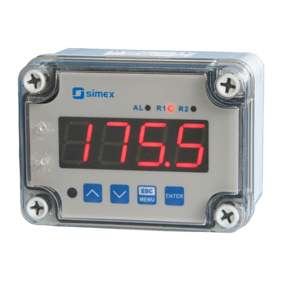
User manual - METER SRT-N118-XA 5. FRONT PANEL DESCRIPTION alarm LED indicator (AL) Thresholds exceeding LED indicators (R) display infrared ENTER receiver MENU programming pushbuttons Symbols and functions of push-buttons: Symbol used in the manual: [ESC/MENU] Functions: MENU • Enter to main menu ( press and hold by at least 2 sec.) •... -
Page 18: Detection Of The Peak Values
6.2. DETECTION OF THE PEAK VALUES The SRT-N118-XA controller is equipped with peaks detection function. It can detect a peaks of the input signal and display their values. Presets connected with this function are placed in ”HOLd” menu (see description of ”HOLd” menu). The detection of the peak can be done if the measured signal raises and drops of value at least equal to parameter ”PEA”... -
Page 19: Control Of The Relay Outputs
User manual - METER SRT-N118-XA 6.3. CONTROL OF THE RELAY OUTPUTS The control of the object (measured signal) is realized via relay outputs. Front panel LEDs named „ R ” indicates the state of particular relay output. If device is not equipped with one or more relay outputs, menus refer to this relays are available, but apply to LED indicators only. -
Page 20: One Threshold Mode
User manual - METER SRT-N118-XA 6.3.1. One threshold mode Figure 6.4 presents the principle of relay outputs operation for one threshold mode, and an example values of other parameters. measured “SEtP” parameter displayed value signal (expected signal value) zone A “HYSt”... -
Page 21: Two Thresholds Mode
User manual - METER SRT-N118-XA The state of relay output while the input value exceeds the border values (points A, B, C, D) is described by parameter “modE”. The relay can be turned on ( “modE” = ”on” ), or turned off (“modE”... -
Page 22: Device Programming
User manual - METER SRT-N118-XA “SEtP” and “SEt2” thresholds. While the controlling process, the relay output changes his state depends of both “SEtP” and “SEt2” thresholds in similar way as it was described in one threshold mode. If two threshold mode is used, “modE” parameter defines state of the relay output when the input value occurs in a particular zone defined by border values of both thresholds . -
Page 23: Parameters Edition
User manual - METER SRT-N118-XA Functions of the buttons while sub-menu and parameters choice: Selection of sub-menu or parameter for editing. Name of selected item (sub- menu or parameter) is displayed. Operation of [ENTER] button depend on present menu position: ENTER •... -
Page 24: Switch Parameters ("List" Type)
User manual - METER SRT-N118-XA Press [ENTER] at least 2 seconds to accept the changes, after that question ”Set?” is displayed, and user must to confirm (or cancel) the changes. To conform changes (and story it in EEPROM) press [ENTER] button shortly after ”SEt?” is displayed. To cancel the changes press [ESC] button shortly after ”SEt?”... -
Page 25: Rel1" Menu
User manual - METER SRT-N118-XA 7.3.1. “rEL1” menu This menu allows to configure the operation mode of relays and LEDs marked „ R ” (e.g. „ R1 ”). If there are few relay outputs available, then every output has its own configuration menu (e.g. - Page 26 User manual - METER SRT-N118-XA - two threshold mode, relay is turned ON when the input value is bigger “out” than “bigger threshold + HYSt” and lower than “lower threshold – HYSt” , and turned on when the input signal is contained in the second zone.
-
Page 27: Inpt" Menu
User manual - METER SRT-N118-XA • If option “noCH” is selected for “AL” parameter, behaviour of the relay may depend on “FiLt” parameter in some cases. If “FiLt” is set to big value and the input signal drops, result value of the measure will change slow, causes of turning on or off relay due to thresholds values. -
Page 28: Outp" Menu
User manual - METER SRT-N118-XA 7.3.3. ”OutP” menu This menu contains parameters of analogue output control. Menu is available if the device is equipped witch analogue output. Analogue output can be controlled depend on both present measured value and peak value (if peak detection is enabled). -
Page 29: Bri" Parameter
User manual - METER SRT-N118-XA ” Lo r ”, ” Hi r ” - this parameters define the output value range. If calculated output value Out exceeds defined range then analogue output generates signal equal to upper or lower border of the defined range. These parameters defines the percentage extension of nominal analogue range (with 0,1% resolution). -
Page 30: Hold" Menu
User manual - METER SRT-N118-XA 7.3.5. ”HOLd” menu This menu contains parameters connected with peak detection function. See also full description of the peak detection function in paragraph: DETECTION OF THE PEAK VALUES “modE” - the type of detected changes of the input signal, can be set to values: ”norm”... -
Page 31: Rs" Menu
User manual - METER SRT-N118-XA 7.3.7. ”rS” menu This menu is connected with RS-485 interface, and sets his properties: ”Addr” - this parameter defines the address of the device, accordingly to Modbus protocol. It can be set in range from 0 to 199. If the value 0 is set then device, responds to frames with address 255 (FFh). -
Page 32: Edit" Parameter
User manual - METER SRT-N118-XA 7.3.8. ”Edit” paramet er This parameter allows to change the edition mode of numerical parameters: ”dig” - the change to “by digit” mode, ”Slid” - slide change mode. 7.3.9. ”dEFS” parameter This setting allows to restore the factory settings of the device. To get the access to this option special password is required: „5465”, next the device displays acknowledge question... -
Page 33: Menu Structure
User manual - METER SRT-N118-XA 7.4. MENU STRUCTURE Measurement mode Press and hold at least 2 seconds MENU MENU 4-digit user password entering (if it is different from „0000”) 0 _ _ _ ENTER ENTER ENTER Parameter MENU rEL1 SEtP... - Page 34 User manual - METER SRT-N118-XA See previous page ENTER ENTER Parameter MENU HOLd modE edition ENTER MENU timE Hdis MENU H r1 H r2 HOut option ENTER ENTER MENU Parameter SECu Scod edition ENTER MENU A r1 MENU A r2...
-
Page 35: The Alarm Led
User manual - METER SRT-N118-XA 8. THE ALARM LED Alarm LED (AL) lights in cases: • exceeding of permissible measurement range • detection of sensor malfunction (break of measurement circuit) 9. CURRENT OUTPUT VALUE CALCULATION Lets assume that we have active current output and its parameters are: “modE”... - Page 36 User manual - METER SRT-N118-XA Register Write Range Register description see measurement Measurement value (no decimal point) range The status of the current measurement; 0h - data valid; A0h - 0h, A0h, 60h top border of the measurement range is exceeded; 60h - bottom border of the measurement range is exceeded;...
- Page 37 User manual - METER SRT-N118-XA Register Write Range Register description “mbtO” parameter in “rS” menu (maximum delay between 0 ÷ 99 received frames); 0 - no delay checking; 1 ÷ 99 - maximum delay expressed in seconds “bri” parameter (display brightness);...
-
Page 38: Transmission Errors Description
User manual - METER SRT-N118-XA Register Write Range Register description “PEA” parameter in “HOLd” menu (minimum detectable 0 ÷ 9999 change, no decimal point included) “timE” parameter in “HOLd” menu, maximum peaks' 0 ÷ 199 (or drops') display time expressed in seconds “HdiS”... - Page 39 Data byte count in answer frame DATA H,L Data byte (Hi and Lo byte) CRC L,H CRC error check (Hi and Lo byte) 1. Read of the displayed value (measurement), SRT-N118-XA device address = 01h: ADDR FUNC REG H,L COUNT H,L...
- Page 40 User manual - METER SRT-N118-XA ADDR FUNC REG H,L DATA H,L CRC L,H DATA H - 0 DATA L - new device address (2) The answer (the same as the message): ADDR FUNC REG H,L DATA H,L CRC L,H 4. Change of baud rate of all devices connected to the net (BROADCAST message).
-
Page 41: Default And User's Settings List
User manual - METER SRT-N118-XA 11. DEFAULT AND USER'S SETTINGS LIST Desc. Parameter Description Default value User's value page Parameters of relay R1 operation (“rEL1” menu) SEtP Relay R1 threshold 20.0 SEt2 Relay R1 second threshold 40.0 HYSt Hysteresis of relay R1... - Page 42 User manual - METER SRT-N118-XA Desc. Parameter Description Default value User's value page Configuration of peaks detection function (“HOLd” menu) modE Kind of detected changes norm Minimum detected change timE Maximum time of peak displaying HdiS The type of displayed value...
- Page 43 User manual - METER SRT-N118-XA...
- Page 44 SIMEX Sp. z o.o. ul. Wielopole 11 80-556 Gdańsk Poland tel.: (+48 58) 762-07-77 fax: (+48 58) 762-07-70 http://www.simex.pl e-mail: info@simex.pl...
Need help?
Do you have a question about the SRT-N118-XA and is the answer not in the manual?
Questions and answers