Table of Contents
Advertisement
Quick Links
Input type: Pt100/500/1000
•
Wall mounting case IP 67
•
Read the user's manual carefully before starting to use the unit or software.
Producer reserves the right to implement changes without prior notice.
2018.12.20
User manual
METER
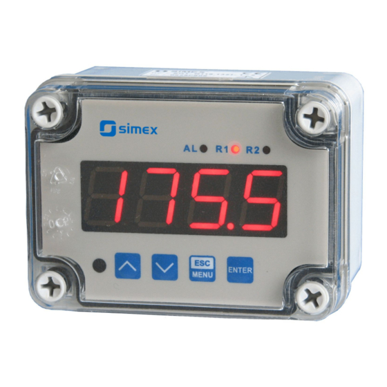
SRT-N118
Assisting the automation
industry since 1986
SRT-N118_INSSXEN_v.2.11.001
Advertisement
Table of Contents

Related Manuals for Simex SRT-N118


Summary of Contents for Simex SRT-N118
- Page 1 Assisting the automation industry since 1986 User manual METER SRT-N118 Input type: Pt100/500/1000 • Wall mounting case IP 67 • Read the user's manual carefully before starting to use the unit or software. Producer reserves the right to implement changes without prior notice.
-
Page 2: Table Of Contents
User manual - METER SRT-N118 CONTENTS 1. BASIC REQUIREMENTS AND USER SAFETY..................3 2. GENERAL CHARACTERISTICS........................4 3. TECHNICAL DATA............................5 4. DEVICE INSTALLATION..........................7 4.1. UNPACKING............................7 4.2. ASSEMBLY............................7 4.3. CONNECTION METHOD........................8 4.4. MAINTENANCE..........................17 5. FRONT PANEL DESCRIPTION........................17 6. PRINCIPLE OF OPERATION........................18 6.1. MEASUREMENT MODE........................18... -
Page 3: Basic Requirements And User Safety
User manual - METER SRT-N118 Explanation of symbols used in the manual: - This symbol denotes especially important guidelines concerning the installation and operation of the device. Not complying with the guidelines denoted by this symbol may cause an accident, damage or equipment destruction. -
Page 4: General Characteristics
To allow user to change presets without opening the cover, an IR sensor is mounted. Remote controller keyboard is equivalent to the device keyboard (Note, that remote controller is not a part of the SRT-N118 set – it is an additional equipment). -
Page 5: Technical Data
User manual - METER SRT-N118 3. TECHNICAL DATA Power supply voltage 85...230...260V AC/DC; 50 ÷ 60 Hz (separated) (depending on version) or 19... 24 ...50V DC and 16... 24 ...35V AC (separated) External fuse (required) T - type, max. 2 A Power consumption max. - Page 6 User manual - METER SRT-N118 Baud rate 1200 bit/s ÷ 115200 bit/s Display LED, 4 digit, 20mm height, red or (depending on version) LED, 4 digit, 38mm height, green Data memory non-volatile memory, EEPROM type Protection level of device IP 67...
-
Page 7: Device Installation
User manual - METER SRT-N118 4. DEVICE INSTALLATION The unit has been designed and manufactured in a way assuring a high level of user safety and resistance to interference occurring in a typical industrial environment. In order to take full advantage of these characteristics installation of the unit must be conducted correctly and according to the local regulations. -
Page 8: Connection Method
User manual - METER SRT-N118 110 mm 67 mm 90 mm Figure 4.1. Device and assembly dimensions 4.3. CONNECTION METHOD Caution - Installation should be conducted by qualified personnel . During installation all available safety requirements should be considered. The fitter is responsible for executing the installation according to this manual, local safety and EMC regulations. - Page 9 User manual - METER SRT-N118 - If the unit is equipped with housing, covers and sealing to, protecting against water intrusion, pay special attention to their correct tightening or clamping. In the case of any doubt consider using additional preventive measures (covers, roofing, seals, etc.).
- Page 10 User manual - METER SRT-N118 Figure 4.3. Method of connecting cables to the clamping connectors All connections must be made while power supply is disconnected ! 12 11 10 (option) (option) RS - 485 Pt100/500/1000 12 11 10 9 8 7...
- Page 11 User manual - METER SRT-N118 12 11 10 OC1, OC2: U max = 30V DC, max = 30mA, max = 100mW RS - 485 (option) (option) Pt100/500/1000 12 11 10 9 8 7 (+5%, -10%) Imax = 100 mA Pt100/500/1000 Figure 4.5.
- Page 12 User manual - METER SRT-N118 12 11 10 OC1: U max = 30V DC, max = 30mA, max = 100mW ACTIVE current output RS - 485 (option) (option) Pt100/500/1000 12 11 10 9 8 7 (+5%, -10%) Imax = 100 mA Pt100/500/1000 Figure 4.7.
- Page 13 User manual - METER SRT-N118 12 11 10 OC1: U max = 30V DC, max = 30mA, max = 100mW Passive, isolated current output 4÷20mA RS - 485 (option) (option) Pt100/500/1000 12 11 10 9 8 7 (+5%, -10%) Imax = 100 mA Pt100/500/1000 Figure 4.9.
- Page 14 User manual - METER SRT-N118 12 11 10 OC1: U max = 30V DC, max = 30mA, max = 100mW ACTIVE voltage output RS - 485 (option) (option) Pt100/500/1000 12 11 10 9 8 7 (+5%, -10%) Imax = 100 mA Pt100/500/1000 Figure 4.11.
- Page 15 User manual - METER SRT-N118 5 4 3 FUSE FUSE Depending on version: 85...230...260V AC/DC; 50 ÷ 60 Hz or 19...24...50V DC and 16...24...35V AC Figure 4.13. Connection of power supply and relays Contacts of relay outputs are not equipped with spark suppressors. While use the relay outputs for switching of inductive loads (coils, contactors, power relays, electromagnets, motors etc.) it is required...
- Page 16 User manual - METER SRT-N118 Logic controller LED 10 mA voltage input Figure 4.15. Example of OC-type outputs connection ACTIVE Current output Logic controller Current input 0-20 mA Figure 4.16. Example of active current outputs connection (for device with active current output only)
-
Page 17: Maintenance
User manual - METER SRT-N118 ACTIVE voltage output Logic controller voltage input 0 - 10V Figure 4.18. Example of active voltage outputs connection (for device with active voltage output only) 4.4. MAINTENANCE The unit does not have any internal replaceable or adjustable components available to the user. -
Page 18: Principle Of Operation
User manual - METER SRT-N118 Symbols and functions of push-buttons: Symbol used in the manual: [ESC/MENU] Functions: MENU • Enter to main menu ( press and hold by at least 2 sec.) • Exit the current level and Enter to previous menu (or measure mode) •... -
Page 19: Detection Of The Peak Values
User manual - METER SRT-N118 6.2. DETECTION OF THE PEAK VALUES The SRT-N118 controller is equipped with peaks detection function. It can detect a peaks of the input signal and display their values. Presets connected with this function are placed in ”HOLd”... - Page 20 User manual - METER SRT-N118 state of relay/LED ”SEtP” parameter zone B zone A measure ”HYSt” parameter Figure 6.2. One threshold control of the relay/LED outputs state of relay/LED ”SEtP” or ”SEt2” parameter zone B zone A zone B measure ”HYSt”...
-
Page 21: One Threshold Mode
User manual - METER SRT-N118 6.3.1. One threshold mode Figure 6.4 presents the principle of relay outputs operation for one threshold mode, and an example values of other parameters. measured “SEtP” parameter displayed value signal (expected signal value) zone A “HYSt”... -
Page 22: Two Thresholds Mode
User manual - METER SRT-N118 The state of relay output while the input value exceeds the border values (points A, B, C, D) is described by parameter “modE”. The relay can be turned on ( “modE” = ”on” ), or turned off (“modE”... -
Page 23: Device Programming
User manual - METER SRT-N118 Figure 6.5 presents the principle of relay outputs operation for two thresholds mode, and an example values of other parameters. In this mode parameter “SEt2” is accessible in common with “SEtP” , this parameter describes a second threshold of the relay output. The parameters “HYSt”, “modE”, “t on”, “toFF”, “unit”... -
Page 24: Parameters Edition
User manual - METER SRT-N118 Functions of the buttons while sub-menu and parameters choice: Selection of sub-menu or parameter for editing. Name of selected item (sub- menu or parameter) is displayed. Operation of [ENTER] button depend on present menu position: ENTER •... -
Page 25: Switch Parameters ("List" Type)
User manual - METER SRT-N118 Press [ENTER] at least 2 seconds to accept the changes, after that question ”Set?” is displayed, and user must to confirm (or cancel) the changes. To conform changes (and story it in EEPROM) press [ENTER] button shortly after ”SEt?” is displayed. To cancel the changes press [ESC] button shortly after ”SEt?”... -
Page 26: Rel1" Menu
User manual - METER SRT-N118 7.3.1. “rEL1” menu This menu allows to configure the operation mode of relays and LEDs marked „ R ” (e.g. „ R1 ”). If there are few relay outputs available, then every output has its own configuration menu (e.g. - Page 27 User manual - METER SRT-N118 - two threshold mode, relay is turned ON when the input value is bigger “out” than “bigger threshold + HYSt” and lower than “lower threshold – HYSt” , and turned on when the input signal is contained in the second zone.
-
Page 28: Inpt" Menu
User manual - METER SRT-N118 If option “ noCH ” is selected for “AL” parameter, behaviour of the relay may • depend on “FiLt” parameter in some cases. If “FiLt” is set to big value and the input signal drops, result value of the measure will change slow, causes of turning on or off relay due to thresholds values. - Page 29 User manual - METER SRT-N118 ”OUtL” - this parameter determines the input value for which the output signal is minimal (depend of output mode „ Omod ”). “OUtH” - this parameter determines the input value for which the output signal is maximal (depend of output mode „Omod”).
-
Page 30: Bri" Parameter
User manual - METER SRT-N118 For passive current output: “noCH” - current will not change, “22.1” - current will be set to 22.1 mA, “3.4” - current will be set to 3.4 mA, For active voltage output: “noCH” - voltage will not change, “11.0”... -
Page 31: Secu" Menu
User manual - METER SRT-N118 7.3.6. ”SECu” menu This menu contains presets connected with availability of other parameters: “Scod” - user password (4-digits number). If this parameter is set at value “0000” , user password is turned off. If the user do not remember his password, the access to the menu is possible by the “one-use password”. -
Page 32: Edit" Parameter
User manual - METER SRT-N118 ”Std” - answer as quick as possible, no additional delay ” 10c” ” 20c” - answer delayed of 10, 20, 50, 100 of 200 chars respectively, where ” 50c” one character time depends on selected baud rate ”100c”... -
Page 33: Menu Structure
User manual - METER SRT-N118 7.4. MENU STRUCTURE Measurement mode Press and hold at least 2 seconds MENU 4-digit user password entering (if it is different from „0000”) MENU 0 _ _ _ ENTER ENTER ENTER Parameter MENU rEL1 SEtP... - Page 34 User manual - METER SRT-N118 See previous page ENTER ENTER Parameter MENU modE HOLd edition ENTER MENU timE Hdis MENU H r1 H r2 HOut option ENTER ENTER Parameter MENU SECU Scod edition ENTER MENU A r1 MENU A r2...
-
Page 35: The Alarm Led
User manual - METER SRT-N118 8. THE ALARM LED Alarm LED (AL) lights in cases: • exceeding of permissible measurement range • detection of sensor malfunction (shortcut or break of measurement circuit) 9. ANALOGUE OUTPUT VALUE CALCULATION Lets assume that we have active current output and its parameters are: “modE”... - Page 36 User manual - METER SRT-N118 Register Write Range Register description -999 ÷ 6000 Measurement value (no decimal point) The status of the current measurement; 0h - data valid; A0h - top 0h, A0h, 60h border of the measurement range is exceeded; 60h - bottom border of the measurement range is exceeded;...
- Page 37 User manual - METER SRT-N118 Register Write Range Register description “Edit” parameter (numerical parameters edit mode); 0 ÷ 1 0 - „dig” mode; 1 - „SLid” mode -999 ÷ 9999 “SEtP” parameter in “rEL1” menu, no decimal point included -999 ÷ 999 “HySt”...
- Page 38 User manual - METER SRT-N118 Register Write Range Register description “HOUt” parameter in “HOLd” menu: 0 ÷ 1 0 - “rEAL” mode ; 1 - “HOLd” mode “Omod” parameter in “OUtP” menu (active current output mode) current output disabled; 1 - current output enabled with 4÷20mA...
-
Page 39: Transmission Errors Description
Data byte count in answer frame DATA H,L Data byte (Hi and Lo byte) CRC L,H CRC error check (Hi and Lo byte) 1. Read of the displayed value (measurement), SRT-N118 device address = 01h: ADDR FUNC REG H,L COUNT H,L... - Page 40 User manual - METER SRT-N118 b) The answer (if an error occur): ADDR FUNC ERROR CRC L,H ERROR - error code = 60h, bottom border of the measurement range is exceeded 2. Read of device ID code ADDR FUNC REG H,L...
-
Page 41: Default And User's Settings List
User manual - METER SRT-N118 5. Read of the registers 1, 2 and 3 in one message (example of reading a number of registries in one frame): ADDR FUNC REG H,L COUNT H,L CRC L,H COUNT L - the count of being read registers (max.16) - Page 42 User manual - METER SRT-N118 Desc. Parameter Description Default value User's value page toFF Turn off delay of relay R2 unit Unit of “t on”, “toFF” parameters of relay R2 Reaction for critical situation of relay R2 Configuration of measurement input (“inPt” menu)
- Page 43 User manual - METER SRT-N118 Desc. Parameter Description Default value User's value page Minimum detected change timE Maximum time of peak displaying HdiS The type of displayed value HOLd H r1 Source of relay R1, and LED R1 control rEAL...
- Page 44 SIMEX Sp. z o.o. ul. Wielopole 11 80-556 Gdańsk Poland tel.: (+48 58) 762-07-77 fax: (+48 58) 762-07-70 http://www.simex.pl e-mail: info@simex.pl...
Need help?
Do you have a question about the SRT-N118 and is the answer not in the manual?
Questions and answers