Table of Contents
Advertisement
Quick Links
Firmware: v.5.21 or higher
•
Input type: 0/4-20 mA, 0/1-5V, 0/2-10V
•
Wall mounting case IP 65 / IP 67
•
Read the user's manual carefully before starting to use the unit or software.
Producer reserves the right to implement changes without prior notice.
2013.06.03
User manual
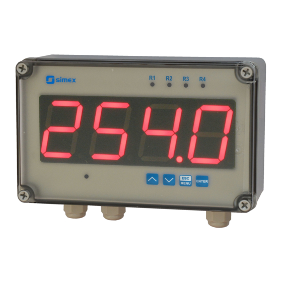
METER
SRP-457
Assisting the automation
industry since 1986
SRP-457_INSSXEN_v.2.07.001
Advertisement
Table of Contents

Related Manuals for Simex SRP-457


Summary of Contents for Simex SRP-457
- Page 1 Assisting the automation industry since 1986 User manual METER SRP-457 Firmware: v.5.21 or higher • Input type: 0/4-20 mA, 0/1-5V, 0/2-10V • Wall mounting case IP 65 / IP 67 • Read the user's manual carefully before starting to use the unit or software.
-
Page 2: Table Of Contents
User manual - METER SRP-457 CONTENTS 1. BASIC REQUIREMENTS AND USER SAFETY..................3 2. GENERAL CHARACTERISTICS........................4 3. TECHNICAL DATA............................4 4. DEVICE INSTALLATION..........................6 4.1. UNPACKING............................6 4.2. ASSEMBLY............................6 4.3. CONNECTION METHOD........................8 4.4. MAINTENANCE..........................12 5. FRONT PANEL DESCRIPTION........................13 6. PRINCIPLE OF OPERATION........................13 6.1. MEASUREMENT MODE........................13... -
Page 3: Basic Requirements And User Safety
User manual - METER SRP-457 Explanation of symbols used in the manual: - This symbol denotes especially important guidelines concerning the installation and operation of the device. Not complying with the guidelines denoted by this symbol may cause an accident, damage or equipment destruction. -
Page 4: General Characteristics
To allow user to change presets without opening the cover, an IR sensor is mounted. Remote controller keyboard is equivalent to the device keyboard (Note, that remote controller is not a part of the SRP-457 set – it is an additional equipment). - Page 5 User manual - METER SRP-457 Voltage measurement accuracy ± 0,1% @ 25°C; ± one digit (for 0÷10 V range) Voltage input resistance > 50 kΩ Temperature stability 50 ppm / °C Display range -999 ÷ 9999, plus decimal point Accepted prolonged input overload: 20%...
-
Page 6: Device Installation
User manual - METER SRP-457 This is a class A unit. In a residential or a similar area it can cause radio frequency interference. In such cases the user can be requested to use appropriate preventive measures. 4. DEVICE INSTALLATION The unit has been designed and manufactured in a way assuring a high level of user safety and resistance to interference occurring in a typical industrial environment. -
Page 7: Connection Method
User manual - METER SRP-457 213 mm 118.2 mm ø10 198 mm 69 mm Figure 4.1. Device and assembly dimensions of F-type case 230 mm 96.5 mm 212 mm Figure 4.2. Device and assembly dimensions of T-type case 4.3. CONNECTION METHOD... - Page 8 User manual - METER SRP-457 - Installation should be conducted by qualified personnel . During installation all available safety requirements should be considered. The fitter is responsible for executing the installation according to this manual, local safety and EMC regulations.
- Page 9 User manual - METER SRP-457 recommended. Twisted pair (best if shielded) must be used with RS-485 serial transmission connections. In the case of measurement or control signals are longer than 30m or go outside of the – building then additional safety circuits are required.
- Page 10 User manual - METER SRP-457 RS - 485 0-20mA Power +24V ±5% 4-20mA DATA+ supply (optional) max = 100mA (depending on version) DATA- n.c. n.c. 7 8 9 10 11 12 13 14 15 16 OC1: U max = 30V DC,...
- Page 11 User manual - METER SRP-457 internally connected 24V DC 10 11 12 13 14 15 16 12 13 14 15 16 Figure 4.8. Connection of voltage converters FUSE FUSE Depending on version: 85...230...260V AC/DC or 19...24...50V DC; 16...24...35V AC Figure 4.9. Connection of power supply and relays Contacts of relay outputs are not equipped with spark suppressors.
-
Page 12: Maintenance
User manual - METER SRP-457 Figure 4.10. Examples of suppression circuit connection: a) to relay terminals; b) to the inductive load 10 11 10 11 LED 10 mA voltage input 24 V Logic controller Figure 4.11. Example of OC-type outputs connection 4.4. -
Page 13: Front Panel Description
User manual - METER SRP-457 Product marked with this symbol should not be placed in municipal waste. Please check local regulations for disposal of electronic products. 5. FRONT PANEL DESCRIPTION Thresholds exceeding LED indicators (R) display infrared receiver programming ENTER... -
Page 14: Detection Of The Peak Values
Configuration of the device (via menu or RS-485 interface) do not stops measures . 6.2. DETECTION OF THE PEAK VALUES The SRP-457 controller is equipped with peaks detection function. It can detect a peaks of the input signal and display their values. Presets connected with this function are placed in... -
Page 15: Control Of The Relay Outputs
User manual - METER SRP-457 ”HOLd” menu (see description of ”HOLd” menu). The detection of the peak can be done if the measured signal raises and drops of value at least equal to parameter ”PEA”. Detected peaks are displayed during the time defined by parameter ”timE” . If a new peak will be detected while one is displayed, this new peak will be displayed and display time counter will be cleared (Figure 6.3). -
Page 16: One Threshold Mode
User manual - METER SRP-457 state of relay/LED ”SEtP” parameter zone B zone A measure ”HYSt” parameter Figure 6.4. One threshold control of the relay/LED outputs state of relay/LED ”SEtP” or ”SEt2” parameter zone B zone B zone A measure ”HYSt”... - Page 17 User manual - METER SRP-457 measured “SEtP” parameter displayed value signal (expected signal value) zone A “HYSt” parameter (allowed signal zone B deviation) time relay state (modE = on closed t on = 0 open toFF = 0) time relay state...
-
Page 18: Two Thresholds Mode
User manual - METER SRP-457 The parameter “AL” allow user to set the relay output behaviour in critical situations (e. g. Input values exceeds permissible measurement range). User can select that the relays will be turned on, turned off,or not changed in critical situations. -
Page 19: Device Programming
User manual - METER SRP-457 the input value occurs in a particular zone defined by border values of both thresholds . The relay can be turned on if the input value is contained in zone A (“modE” = ”in”) or zone B ( “modE”... -
Page 20: Parameters Edition
User manual - METER SRP-457 Functions of the buttons while sub-menu and parameters choice: Selection of sub-menu or parameter for editing. Name of selected item (sub- menu or parameter) is displayed. Operation of [ENTER] button depend on present menu position: ENTER •... -
Page 21: Switch Parameters ("List" Type)
User manual - METER SRP-457 Press [ENTER] at least 2 seconds to accept the changes, after that question ”Set?” is displayed, and user must to confirm (or cancel) the changes. To conform changes (and story it in EEPROM) press [ENTER] button shortly after ”SEt?” is displayed. To cancel the changes press [ESC] button shortly after ”SEt?”... - Page 22 User manual - METER SRP-457 If there are few relay outputs available, then every output has its own configuration menu (e.g. menu „rEL2” for relay (LED) „R2”). Principle of the relays operation is described in paragraph CONTROL OF THE RELAY OUTPUTS.
- Page 23 User manual - METER SRP-457 - two threshold mode, relay is turned ON when the input value is bigger “out” than “bigger threshold + HYSt” and lower than “lower threshold – HYSt” , and turned on when the input signal is contained in the second zone.
-
Page 24: Beep" Menu
User manual - METER SRP-457 7.3.2. “bEEP” menu This menu contains options connected with acoustic signal : "AL” - if this parameter is set to “on”, any critical situation causes by acoustic signal " r1 ” - if this parameter is set to “ on ”, activation of relay R1 causes by acoustic signal "r2"... - Page 25 User manual - METER SRP-457 “ 0”, “ 0.0”, “ 0.00”, “0.000” Decimal point position is changed by [^] , [v] buttons. These parameters describe the values displayed for minimum and maximum input “Lo C” current. For example, if input type is set to 4-20 mA “Lo C” parameter defines the “Hi C”...
- Page 26 User manual - METER SRP-457 (see Info below), „t Sh” - the measuring range, this parameter has the fixed precision - 2-decimal point. The unit value of “ t Sn ” parameter is 100-fold less than the unit value of •...
- Page 27 User manual - METER SRP-457 t h3 t Sh t h2 h~I[mA] t Sn t h1 Figure 7.1 Parameters of cylindrical tank in vertical position. t h1 t h2 t h3 t Sh h~I[mA] t Sn Figure 7.2 Parameters of cylindrical tank in horizontal position.
- Page 28 User manual - METER SRP-457 (parameter “CHAr” = ”USEr” ) the If user defined characteristic is selected parameters „Lo C” and „Hi C” are not available for modification, due to their values are calculated from defined characteristic. “AddP” - this menu allow user to add single point to the user defined characteristic.
-
Page 29: Bri" Parameter
User manual - METER SRP-457 ”Lo r” = 75,0% (3 mA) ”Hi r” = 5,0 % (1 mA) nominal measurement range (4-20mA) [mA] permissible measurement range measurement result is displayed display display regardless on nominal range exceeding message ”-Lo-” message ”-Hi-”... -
Page 30: Secu" Menu
User manual - METER SRP-457 “PEA” - minimal detected signal change classified as peak or drop (see Figure 6.3) “timE” - maximum time of displaying of the peak (drop) value, can be set from 0.0 to 19.9 sec, with 0.1 sec. resolution. If „ HdiS ”=” HOLD ” then setting parameter "timE" = 0.0 causes holding peak value until [ESC] button is pressed. -
Page 31: Edit" Parameter
User manual - METER SRP-457 ”mbAc” - this parameter sets the access to the configuration registers of the device. Possible values: ”on” - configuration registers can be set via RS-485 interface, ”oFF” - configuration registers can not be set via RS-485 interface. -
Page 32: Defs" Parameter
User manual - METER SRP-457 7.3.9. ”dEFS” parameter This setting allows to restore the factory settings of the device. To get the access to this option special password is required: „5465”, next the device displays acknowledge question „SEt?” . Press [ENTER] to acknowledge the restoring of factory settings or [ESC] to cancel. -
Page 33: Menu Structure
User manual - METER SRP-457 7.4. MENU STRUCTURE Measurement mode Press and hold at least 2 seconds MENU MENU 4-digit user password entering (if it is different from „0000”) 0 _ _ _ ENTER ENTER ENTER Parameter MENU rEL1 SEtP... - Page 34 User manual - METER SRP-457 See previous page ENTER ENTER Parameter MENU modE HOLd edition ENTER MENU timE Hdis MENU H r1 H r2 H r3 H r4 ENTER ENTER Parameter MENU SECu Scod edition ENTER MENU A r1 A r2...
-
Page 35: Over-Current Protection
User manual - METER SRP-457 8. OVER-CURRENT PROTECTION The current input of the device is equipped with over-current protection circuit. This circuit protects the standard resistor against damage. Maximum input current is set to 40mA (typical). When temperature of the standard resistor falls, the protection circuit will turn on automatically, and the device will measure the input current again. -
Page 36: Linear Characteristic
User manual - METER SRP-457 9.1.1. Linear characteristic The normalized result is converted by fixed coefficients determined by “Lo C” and “Hi C” parameters (when the normalized results is equal 0, then value “Lo C” is displayed, and when the normalized results is equal 1, then value “Hi C” is displayed). Expression presented below... -
Page 37: Square Root Characteristic
User manual - METER SRP-457 9.1.3. Square root characteristic The normalized result is rooted and further conversion is done as for linear characteristic. Conversion is made accordingly with the expression: × "Hi C" −"Lo C" "Lo C" , where W means the displayed value. -
Page 38: Volume Characteristics Of A Cylindrical Tank
User manual - METER SRP-457 Normalized measurement I (for 0-20 mA range) 0,35 5-elements characteristic X (PH) = „70.0.” Y (PH) X = „35.0.” Y (PL) X (PL) = „50.0.” X = „20.0.” Prąd wejściowy [mA] X = „90.0.” X = „100.0.”... -
Page 39: Examples Of Calculations
User manual - METER SRP-457 ∫ ⋅dh Possible combination of tank shape for calculation the volume: cylindrical tank in vertical position cylindrical tank in horizontal position parameter t h2=0 t h3=0 t h2=0 t h1=0 t h1=0 t h1=0 s setting... - Page 40 User manual - METER SRP-457 respectively. The calculations will be done for three different input currents from example 2. a) I =10 mA and I = 0,375 Accordingly to expression on page 36 for linear characteristic: 0,375 × [1200 -(- 300)] ≅ 562 and next, the “Lo C” value is added to the result , so the displayed value: W ≅...
- Page 41 User manual - METER SRP-457 it is necessary to enter X and Y coordinates of 11 points (see Menu ”inPt”). The calculations will be done for three different input currents from example 2, so in calculations some of the segments will be used only.
- Page 42 User manual - METER SRP-457 „ t h2 ”=10,00 „t h3”=00,00 „ t d ”=04,00 Input current [mA] Figure 9.6 The volume characteristic of tank depending on input current in 4÷20mA range. Example 8: Volume characteristics of a cylindrical tank in the horizontal position We assume that the user has tank for wheat in the shape of the cylinder located in horizontal position.
-
Page 43: The Modbus Protocol Handling
User manual - METER SRP-457 I [mA] Figure 9.7 The volume characteristic of tank depending on input current in 4÷20mA range. 10. THE MODBUS PRO TOCOL HANDLING Transmission parameters: 1 start bit, 8 data bits, 1 or 2 stop bit (2 bits are send, 1 and 2 bits... -
Page 44: List Of Registers
User manual - METER SRP-457 10.1. LIST OF REGISTERS Register Write Range Register description -999 ÷ 9999 Measurement value (no decimal point) The status of the current measurement; 0h - data valid; A0h - top 0h, A0h, 60h border of the measurement range is exceeded; 60h - bottom border of the measurement range is exceeded;... - Page 45 User manual - METER SRP-457 Register Write Range Register description “mbAc” parameter in “rS” menu (permission to write registers via 0 ÷ 1 RS-485 interface); 0 - write denied ; 1 - write allowed Parameters of “SECU” menu (binary format (0 - „oFF”, 1 - „on”): see descr.
- Page 46 User manual - METER SRP-457 Register Write Range Register description “toFF” parameter in “rEL2” menu, expressed in tenth of seconds 0 ÷ 999 or tenth of minutes depend on “unit” parameter - register no. 3Dh) “unit” parameter in “rEL2” menu: 0 ÷...
-
Page 47: Transmission Errors Description
User manual - METER SRP-457 Register Write Range Register description “H r1” parameter in “HOLd” menu 0 ÷ 1 0 - “rEAL” mode ; 1 - “HOLd” mode “H r2” parameter in “HOLd” menu: 0 ÷ 1 0 - “rEAL” mode ; 1 - “HOLd” mode “H r3”... -
Page 48: Examples Of Query/Answer Frames
Data byte count in answer frame DATA H,L Data byte (Hi and Lo byte) CRC L,H CRC error check (Hi and Lo byte) 1. Read of the displayed value (measurement), SRP-457 device address = 01h: ADDR FUNC REG H,L COUNT H,L... - Page 49 User manual - METER SRP-457 3. Change of the device address from 1 to 2 (write to reg. 20h) ADDR FUNC REG H,L DATA H,L CRC L,H DATA H - 0 DATA L - new device address (2) The answer (the same as the message):...
-
Page 50: Default And User's Settings List
User manual - METER SRP-457 11. DEFAULT AND USER'S SETTINGS LIST Desc. Parameter Description Default value User's value page Parameters of relay R1 operation (“rEL1” menu) SEtP Relay R1 threshold 20.0 SEt2 Relay R1 second threshold 40.0 HYSt Hysteresis of relay R1... - Page 51 User manual - METER SRP-457 Desc. Parameter Description Default value User's value page t on Turn on delay of LED R4 toFF Turn off delay of LED R4 unit Unit of “t on”, “toFF” parameters of LED R4 Reaction for critical situation of LED R4 Activation of acoustic signal (menu “bEEP”)
- Page 52 User manual - METER SRP-457 Desc. Parameter Description Default value User's value page H r3 Source of relay R3, and LED R3 control rEAL H r4 Source of relay R4, and LED R4 control rEAL Settings of access to the configuration parameters (“SECu” menu)
- Page 53 User manual - METER SRP-457...
- Page 54 User manual - METER SRP-457...
- Page 55 User manual - METER SRP-457...
- Page 56 SIMEX Sp. z o.o. ul. Wielopole 7 80-556 Gdańsk Poland tel.: (+48 58) 762-07-77 fax: (+48 58) 762-07-70 http://www.simex.pl e-mail: info@simex.pl...
Need help?
Do you have a question about the SRP-457 and is the answer not in the manual?
Questions and answers