
Related Manuals for TSC TE210 Series


Summary of Contents for TSC TE210 Series
- Page 1 TE200/TE210/TE300/TE310 Series THERMAL TRANSFER/DIRECT THERMAL BAR CODE PRINTER USER’S MANUAL...
- Page 2 Information in this document is subject to change without notice and does not represent a commitment on the part of TSC Auto ID Technology Co. No part of this manual may be reproduced or transmitted in any form or by any means, for any purpose other than the purchaser’s personal use, without the expressed...
- Page 3 Agency Compliance and Approvals TE200/TE300 Series: EN 55032, Class A EN 55024 EN 60950-1 This is a class A product. In a domestic environment this product may cause radio interference in which case the user may be required to take adequate measures.
- Page 4 -Reorient or relocate the receiving antenna. -Increase the separation between the equipment and receiver. -Connect the equipment into an outlet on a circuit different from that to which the receiver is connected. -Consult the dealer or an experienced radio/ TV technician for help. This device complies with Part 15 of the FCC Rules.
- Page 5 KN 32 KN 35 Note: There may have certification differences in the series models, please refer to product label for accuracy. Important safety instructions: 1. Read all of these instructions and keep them for later use. 2. Follow all warnings and instructions on the product. 3.
- Page 6 30mW 5470-5725MHz Hereby, TSC Auto ID Technology Co., Ltd. declares that the radio equipment type [Wi-Fi] IEEE 802.11 a/b/g/n is in compliance with Directive 2014/53/EU The full text of the EU declaration of conformity is available at the following internet address: http:// www.tscprinters.com...
- Page 7 The equipment must not be co-located or operating in conjunction with any other antenna or transmitter. Canada, Industry Canada (IC) Notices This Class B digital apparatus complies with Canadian ICES-003 and RSS-210. Operation is subject to the following two conditions: (1) this device may not cause interference, and (2) this device must accept any interference, including interference that may cause undesired operation of the device.
- Page 8 Ce périphérique a également été évalué et démontré conforme aux limites d'exposition radio-fréquence par l'IC pour des utilisations par des opérateurs mobiles (les antennes sont à moins de 20 cm du corps d'une personne). (Pour le Bluetooth) NCC 警語: 經型式認證合格之低功率射頻電機,非經許可,公司、商號或使用者均不得擅自變更 頻率、加大功率或變更原設計之特性及功能。(即低功率電波輻射性電機管理辦法第十...
-
Page 9: Table Of Contents
Contents 1. Introduction ......................1 1.1 Product Introduction ..................1 1.2 Product Features ....................2 1.2.1 Printer Standard Features ..............2 1.2.2 Printer Optional Features ............... 3 1.3 General Specifications ..................4 1.4 Print Specifications ....................4 1.5 Ribbon Specifications ..................5 1.6 Media Specifications ..................5 2. - Page 10 5.1 Start the Diagnostic Tool ................31 5.2 Printer Function ....................32 5.3 Calibrating Media Sensor by Diagnostic Tool ..........33 5.3.1 Auto Calibration ..................33 6. Troubleshooting ....................34 6.1 Common Problems ..................34 7. Maintenance ....................... 36 Revise History ......................37...
-
Page 11: Introduction
1. Introduction 1.1 Product Introduction Thank you very much for purchasing TSC bar code printer. The TE200/TE210/TE300/TE310 series printer features the single motor that is capable of handling a large capacity of 300 meters ribbon and large rolls of media inside its sleek design. -
Page 12: Product Features
1.2 Product Features 1.2.1 Printer Standard Features The printer offers the following standard features. TE200 TE300 TE210 TE310 (203 dpi (300 dpi (203 dpi (300 dpi Product standard feature model) model) model) model) ○ ○ ○ ○ Thermal transfer printing ○... -
Page 13: Printer Optional Features
Text, bar code, graphics/image printing (Please refer to the TSPL/TSPL2 programming manual for supporting code page) Supported bar code Supported image 1D bar code 2D bar code Code128UCC, GS1 DataBar, BITMAP, Code128 subsets A、 BMP, B 、 C, EAN128, DataMatrix, (Max. -
Page 14: General Specifications
○ Peeler module ○ Regular full cut cutter (Guillotine cutter) Paper thickness: 0.06~0.19 mm ○ Regular full/partial cutter (Guillotine cutter) Paper thickness: 0.06~0.19 mm 1.3 General Specifications General TE200/TE300 TE210/TE310 Specifications 204 mm (W) x 164 mm (H) x 280 mm (L) Physical dimensions Weight 2.4kg... -
Page 15: Ribbon Specifications
1.5 Ribbon Specifications Ribbon Specifications 1” core: Max. 67mm Ribbon outside diameter 0.5” core: Max. 40mm Ribbon length 1” inner core: 300 meters 0.5” inner core: 110 meters Ribbon core inside diameter 0.5 and 1 inch Ribbon width 40 ~ 110 mm Ribbon wound type Outside wound 1.6 Media Specifications... -
Page 16: Operations Overview
2. Operations Overview 2.1 Unpacking and Inspection This printer has been specially packaged to withstand damage during shipping. Please carefully inspect the packaging and printer upon receiving the bar code printer. Please retain the packaging materials in case you need to reship the printer. Unpacking the printer, the following items are included in the carton. -
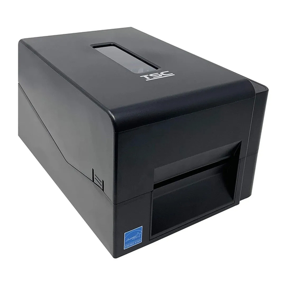
Page 17: Printer Overview
2.2 Printer Overview 2.2.1 Front View LED indicator Feed/Pause button Top cover open tab Paper exit chute... -
Page 18: Interior View
2.2.2 Interior View OPEN Printer top cover Media supply spindle Ribbon supply spindle Platen roller Ribbon supply hub Black mark sensor Ribbon rewind hub Gap sensor Ribbon rewind spindle Media guide Print head release button Media guide adjustment knob Fixing tabs Print head WARNING HAZARDOUS MOVING PARTS... -
Page 19: Rear View
2.2.3 Rear View Power switch Power jack socket USB interface (USB 2.0/Hi-Speed mode) USB host (TE210/TE310 Series only) RS-232 interface (TE210/TE310 Series only) Ethernet interface (TE210/TE310 Series only) Note: The interface picture here is for reference only. Please refer to the product specification for the interfaces availability. -
Page 20: Setup
3. Setup 3.1 Setting up the Printer Place the printer on a flat, secure surface, then follow the steps below: Plug the power cord into the AC power cord socket at the rear of the printer. Then, plug the other side into a properly grounded power outlet. -
Page 21: Loading The Ribbon
3.2 Loading the Ribbon 1. Open the printer top cover by pressing the top cover open tabs located on each side of the printer. 2. Insert the paper core to the ribbon rewind spindle. Note: Please follow the direction when installing the ribbon rewind spindle. - Page 22 4. Push the print head release button to open the print head mechanism. OPEN 5. Insert the ribbon to the ribbon spindle. Note: The ribbon spindle can be substituted by insert the ribbon with notches on both sides to the ribbon mechanism directly.
- Page 23 7. Pull the leader of the ribbon through the print head and stick the leader of the ribbon onto the ribbon rewind paper core. 8. Turn the ribbon rewind hub until the ribbon plastic leader is thoroughly wound and the black section of the ribbon covers the print head.
-
Page 24: Loading The Media
3.3 Loading the Media 3.3.1 Loading the Roll Labels Open the printer top cover by pressing the top cover open tabs located on each side of the printer. Insert the paper roll into the media supply spindle and use two fixing tabs to fix the paper roll onto the center of the spindle. - Page 25 Push the print head release button to open the print head mechanism. Gap sensor Black mark Platen roller sensor Note: The black mark sensor position is moveable and the gap sensor is fixed. Please make sure the gap or black mark is at the location where media gap/black mark will pass through for sensing.
- Page 26 Use “Diagnostic Tool” to set the media sensor type and calibrate the selected sensor. (Start the “Diagnostic tool” Select the “Printer Configuration” tab Click the “Calibrate Sensor” button ) Please refer to section 5.3. Note: * Please calibrate the gap/ black mark sensor when changing media. * Please refer to videos at YouTube.
-
Page 27: External Label Roll Mount Installation (Option)
3.3.2 External Label Roll Mount Installation (Option) 1. Attach the extended plate on the bottom of the printer. 2. Insert a 3” (or 1”) label spindle into a paper roll. Then, install it on the external paper roll mount. 1” label spindle 3”... - Page 28 4. Refer to chapter 3.3.1 to install the label. Use “Diagnostic Tool” to set the media sensor type and calibrate the selected sensor. Note: Please calibrate the gap/black mark sensor when changing media.
-
Page 29: Loading The Media In Cutter Mode (Option)
3.3.3 Loading the Media in Cutter mode (TE210/TE310 Series only, dealer option) Refer to chapter 3.3.1 to install the label. Use “Diagnostic Tool” to set the media sensor type and calibrate the selected sensor. Open the printer top cover by pressing the top cover open tabs located on each side of the printer. - Page 30 Close the print head mechanism as indicated. Close the printer cover. Use the “Diagnostic Tool” to set the printer for cutter mode by selecting “CUTTER” option for Post-Print Action setting then click “Set” button to enable the cutter mode. Press the FEED button to test. Note: Please calibrate the gap/black mark sensor when changing media.
-
Page 31: Loading The Media In Peel-Off Mode (Option)
3.3.4 Loading the Media in Peel-off Mode (TE210/TE310 Series only, dealer option) Refer to chapter 3.3.1 to install the label. Use “Diagnostic Tool” to set the media sensor type and calibrate the selected sensor. Open the printer top cover by pressing the top cover open tabs located on each side of the printer. - Page 32 Open the peel-off cover. Feed the liner into peel-off cover slot. Peel-off cover slot Close the peel-off module. Use the “Diagnostic Tool” to set the peel-off mode by selecting “PEEL” option for Post-Print Action setting then click “Set” button to enable the peel-off mode.
-
Page 33: Led And Button Functions
4. LED and Button Functions This printer has one button and one three-color LED indicator. By indicating the LED with different color and pressing the button, printer can feed labels, pause the printing job, select and calibrate the media sensor, print printer self-test report, reset printer to defaults (initialization). -
Page 34: Gap/Black Mark Sensor Calibration
Power on utilities The LED color will be changed as following pattern: Amber Amber Green Green/Amber Red/Amber Solid green LED color (5 blinks) (5 blinks) (5 blinks) (5 blinks) (5 blinks) Functions 1. Gap / black mark sensor calibration Release 2. -
Page 35: Gap/Black Mark Calibration, Self-Test And Dump Mode
4.3.2 Gap/Black Mark Calibration, Self-test and Dump Mode While calibrate the gap/black mark sensor, printer will measure the label length, print the internal configuration (self-test) on label and then enter the dump mode. To calibrate gap or black mark sensor, depends on the sensor setting in the last print job. Please follow the steps below to calibrate the sensor. - Page 36 Self-test printout Model name F/W version Firmware checksum Printer S/N TSC configuration file System date System time Printed mileage (meter) Cutting counter Print speed (inch/sec) Print darkness...
- Page 37 Numbers of download files Total & available memory space Print head check pattern...
-
Page 38: Printer Initialization
Dump mode Printer will enter dump mode after printing printer configuration. In the dump mode, all characters will be printed in 2 columns as following. The left side characters are received from your system and right side data are the corresponding hexadecimal value of the characters. It allows users or engineers to verify and debug the program. -
Page 39: Set Black Mark Sensor As Media Sensor And Calibrate The Black Mark Sensor
Printer configuration will be restored to defaults as below after initialization. Parameter Default setting Speed 127 mm/sec (5 ips) (203DPI) 76 mm/sec (3 ips) (300DPI) Density 4" (101.5 mm) Label Width 4" (101.5 mm) Label Height Sensor Type Gap sensor 0.12"... -
Page 40: Skip Auto.bas
Amber red (5 blinks) amber (5 blinks) green (5 blinks) green/amber (5 blinks) red/amber (5 blinks) solid green 4.3.6 Skip AUTO.BAS TSPL2 programming language allows user to download an auto execution file to flash memory. Printer will run the AUTO.BAS program immediately when turning on printer power. -
Page 41: Diagnostic Tool
5. Diagnostic Tool TSC’s Diagnostic Utility is an integrated tool incorporating features that enable you to explore a printer’s settings/status; change a printer’s settings; download graphics, fonts and firmware; create a printer bitmap font; and send additional commands to a printer. With the aid of this powerful tool, you can review printer status and settings in an instant, which makes it much easier to troubleshoot problems and other issues. -
Page 42: Printer Function
5.2 Printer Function 1. Select the PC interface connected with bar code printer. The default interface setting is USB interface. If USB interface is connected with printer, no other settings need to be changed in the interface field. 2. Click the “Printer Function” button to setup. 3. -
Page 43: Calibrating Media Sensor By Diagnostic Tool
5.3 Calibrating Media Sensor by Diagnostic Tool 5.3.1 Auto Calibration 1. Make sure the media is already installed and print head mechanism is closed. (Please refer to section 3.3.) Gap sensor Black mark sensor 2. Turn on the printer power switch. 3. -
Page 44: Troubleshooting
6. Troubleshooting 6.1 Common Problems The following guide lists the most common problems that may be encountered when operating this bar code printer. If the printer still does not function after all suggested solutions have been invoked, please contact the Customer Service Department of your purchased reseller or distributor for assistance. - Page 45 must have CRLF at the end of each command line. Memory full * The space of FLASH/DRAM * Delete unused files in the FLASH/DRAM. is full. ( FLASH / DRAM ) * Ribbon and media is loaded * Reload the supply. incorrectly * Clean the print head.
-
Page 46: Maintenance
7. Maintenance This session presents the clean tools and methods to maintain your printer. 1. Please use one of following material to clean the printer. Cotton swab Lint-free cloth Vacuum / Blower brush 100% ethanol 2. The cleaning process is described as following, Printer Part Method Interval... -
Page 47: Revise History
Revise History Date Content Editor... - Page 48 9F., No.95, Minquan Rd., Xindian Dist., No.35, Sec. 2, Ligong 1st Rd., Wujie Township, New Taipei City 23141, Taiwan (R.O.C.) Yilan County 26841, Taiwan (R.O.C.) TEL: +886-2-2218-6789 TEL: +886-3-990-6677 FAX: +886-2-2218-5678 FAX: +886-3-990-5577 Web site: www.tscprinters.com E-mail: printer_sales@tscprinters.com TSC Auto ID Technology Co., Ltd. tech_support@tscprinters.com...
Need help?
Do you have a question about the TE210 Series and is the answer not in the manual?
Questions and answers