TSC TTP-245C Service Manual
Thermal transfer / direct thermal bar code printer
Hide thumbs
Also See for TTP-245C:
- User manual (44 pages) ,
- Programming manual (434 pages) ,
- User manual (37 pages)

Related Manuals for TSC TTP-245C


Summary of Contents for TSC TTP-245C
- Page 1 TTP-245C / TTP-343C / TTP-244CE THERMAL TRANSFER / DIRECT THERMAL BAR CODE PRINTER SERVICE MANUAL...
-
Page 2: Table Of Contents
TTP-245C/ TTP-343C/ TTP-244CE Bar Code Printer Service Manua TABLE OF CONTENT 1. OVERVIEW ........................ 1 1.1 Front View ....................... 1 1.2 Interior View ......................3 1.3 Rear View ......................... 4 2. ELECTRONICS ......................5 2.1 Summary of Board Connectors ................5 2.2 Pin Configuration .................... -
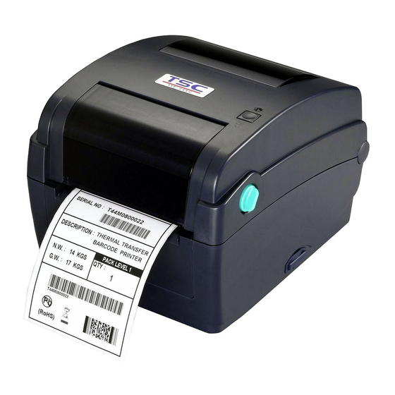
Page 3: Overview
TTP-245C/ TTP-343C/ TTP-244CE Bar Code Printer Service Manua 1. OVERVIEW 1.1 Front View 1. Ribbon access cover 2. Top cover open lever 3. Media view window 4. LED indicator 5. Feed button 6. SD card socket * Recommended SD card specification. - Page 4 TTP-245C/ TTP-343C/ TTP-244CE Bar Code Printer Service Manua V1.0, V1.1 microSD 1 GB Transcend, Panasonic V2.0 SDHC CLASS 4 microSD 4 GB Panasonic V2.0 SDHC CLASS 6 microSD 4 GB Transcend V1.0, V1.1 miniSD 128 MB Transcend, Panasonic V1.0, V1.1...
-
Page 5: Interior View
TTP-245C/ TTP-343C/ TTP-244CE Bar Code Printer Service Manua 1.2 Interior View 1. Ribbon rewind hub 2. Ribbon rewind gear 3. Gap sensor (receiver) 4. Media holder 5. Media holder lock switch 6. Gap sensor (transmitter) 7. Printhead 8. Ribbon supply hub 9. -
Page 6: Rear View
TTP-245C/ TTP-343C/ TTP-244CE Bar Code Printer Service Manua 1.3 Rear View 1. Ethernet interface 2. USB interface 3. Centronics interface 4. RS-232C interface 5. Power jack socket 6. Power switch 7. Fan-fold paper entrance chute... -
Page 7: Electronics
TTP-245C/ TTP-343C/ TTP-244CE Bar Code Printer Service Manual 2. ELECTRONICS 2.1 Summary of Board Connectors Main board Connector Description Remark Power switch Power supply output (24V DC) connector RS-232C connector Centronics port connector USB connector Ethernet connector... - Page 8 TTP-245C/ TTP-343C/ TTP-244CE Bar Code Printer Service Manual Print head connector JP12_1 & JP12_2 (TTP-343C) Print head connector JP30_1 & JP30_2 (TTP-245C / 244CE) Micro processor 5V DC connector JP22 Buzzer (Factory option) RTC battery (Factory option) SD card slot Motor temp.
- Page 9 TTP-245C/ TTP-343C/ TTP-244CE Bar Code Printer Service Manual Peel-off sensor connector JP19 Description Voltage Reserved Emitter on : 2.1~2.3V Peel sensor emitter Emitter off: 2.6~2.8V Peel sensor receiver AD 0~3.3V Head open sensor connector JP16 Description Voltage Power 3.3V 0~1.4V: Head close Head open sensor receiver 1.7~3.3V: Head open...
- Page 10 TTP-245C/ TTP-343C/ TTP-244CE Bar Code Printer Service Manual Main board bottom Connector Description Remark Firmware recover card connector JP37...
-
Page 11: Pin Configuration
TTP-245C/ TTP-343C/ TTP-244CE Bar Code Printer Service Manual 2.2 Pin Configuration RS-232C CONFIGURATION +5 V CONFIGURATION Centronics SPP Mode Nibble In/Out Function A low on this line indicates that there are valid data at the host. When this pin is de-asserted, the +ve... - Page 12 TTP-245C/ TTP-343C/ TTP-244CE Bar Code Printer Service Manual direction, it functions as PtrBusy. Paper Out / When low, device acknowledges reverse request. Select Extensibility flag Ground Ground No Defined 16-17 Ground Ground No Defined 19-30 Ground Ground No Defined A low set by the device indicates that the reverse...
-
Page 13: Mechanism
TTP-245C/ TTP-343C/ TTP-244CE Bar Code Printer Service Manual 3. MECHANISM Please turn off the power switch and unplug the power adapter before replacing parts. 3.1 Replacing Top Cover and Media View Window Cover 1. Turn the printer upside down and use the Phillips screwdriver to remove the 4 screws from hinge holder. - Page 14 TTP-245C/ TTP-343C/ TTP-244CE Bar Code Printer Service Manual Screws Screws 5. Disconnect the harness from the feed button PC board. 6. Remove/Replace the top cover and media view window cover. Media view window Top cover cover 7. Reassemble the parts in the reverse procedure.
-
Page 15: Replacing The Lower Cover
TTP-245C/ TTP-343C/ TTP-244CE Bar Code Printer Service Manual 3.2 Replacing the Lower Cover 1. Turn the printer upside down and use the Phillips screwdriver to remove the 6 screws. Screws Screws 2. Remove/Replace the lower cover. 3. Reassemble the parts in the reverse procedure. -
Page 16: Replacing The Main Board
TTP-245C/ TTP-343C/ TTP-244CE Bar Code Printer Service Manual 3.3 Replacing the Main Board 1. Refer to section 3.2 to remove the lower cover. 2. Remove 1 screw from the main board. Screws 3. Disconnect all connectors from the main board. -
Page 17: Replacing The Platen Roller Assembly
TTP-245C/ TTP-343C/ TTP-244CE Bar Code Printer Service Manual 3.4 Replacing the Platen Roller Assembly 1. Open the printer top cover by pulling the green tabs located on each side towards the front of the printer, then lift the top cover to the maximum open angle. -
Page 18: Replacing The Print Head Assembly
TTP-245C/ TTP-343C/ TTP-244CE Bar Code Printer Service Manual 3.5 Replacing the Print Head Assembly 1. Open the printer top cover by pulling the top cover open levers located on each side towards the front of the printer, then lift the top cover to the maximum open angle. Open the ribbon access cover. - Page 19 TTP-245C/ TTP-343C/ TTP-244CE Bar Code Printer Service Manual 5. Remove the print head harness cover. Print head harness cover 6. Connect the print head harness and carefully insert the print head module spring plate into the ribbon base print head spring plate slot.
-
Page 20: Replacing The Stepping Motor
TTP-245C/ TTP-343C/ TTP-244CE Bar Code Printer Service Manual 3.6 Replacing the Stepping Motor 1. Refer to section 3.2 to remove the lower cover. 2. Disconnect the stepping motor connector from the main board. Stepping motor Stepping motor connector 3. Use the Phillips screwdriver to remove the 2 screws. -
Page 21: Replacing The Feed Button And Feed Button Pcb
TTP-245C/ TTP-343C/ TTP-244CE Bar Code Printer Service Manual 3.7 Replacing the Feed Button and Feed Button PCB 1. Refer to section 3.1 to remove the top cover. Top cover 2. Remove the screws that fixe the feed PCB to the mechanism. -
Page 22: Peel-Off Module Installation (Option)
TTP-245C/ TTP-343C/ TTP-244CE Bar Code Printer Service Manual 3.8 Peel-off Module Installation (Option) 1. Refer to section 3.2 to remove the lower cover. 2. Open the top cover and pull up the front panel from the printer. Thread the 5-pin peel-off module harness through the front slot of lower inner cover. - Page 23 TTP-245C/ TTP-343C/ TTP-244CE Bar Code Printer Service Manual Tenon 5. Then, put back the lower inner cover. 6. Close the top cover and then upside down the printer. 7. Fasten the 6 screws at the lower inner cover. 8. Open the peel-off cover. Disengage one of platen holder tab from lower inner cover and rotate the tab 90 degrees to install the peel-off bar into the both slots.
-
Page 24: Cutter Module Installation (Option)
TTP-245C/ TTP-343C/ TTP-244CE Bar Code Printer Service Manual 3.9 Cutter Module Installation (Option) 1. Refer to section 3.2 to remove the lower cover. 2. Open the top cover and pull up the front panel from the printer. Front panel 3. Thread the cutter module 8-pin harness through the front slot of lower inner cover. - Page 25 TTP-245C/ TTP-343C/ TTP-244CE Bar Code Printer Service Manual 8-pin socket Cutter module 5. Then, put back the lower inner cover. 6. Place the cutter module into the both sides notches of lower inner cover as picture below, then push cutter to lock into the lower inner cover.
-
Page 26: Troubleshooting
TTP-245C/ TTP-343C/ TTP-244CE Bar Code Printer Service Manual 4. TROUBLESHOOTING The following guide lists the most common problems that might be encountered when operating this bar code printer. If the printer still does not function after all suggested solutions have been invoked, please contact the Customer Service Department of your purchased reseller or distributor for assistance. -
Page 27: Print Quality
TTP-245C/ TTP-343C/ TTP-244CE Bar Code Printer Service Manual 4.2 Print Quality Problem Possible Cause Recovery Procedure Check if interface cable is well Re-connect cable to interface. connected to the interface connector. The serial port cable pin configuration is Please replace the cable with pin to pin not pin to pin connected. - Page 28 TTP-245C/ TTP-343C/ TTP-244CE Bar Code Printer Service Manual Check if print density is set properly. Adjust the print density and print speed. Check print head test pattern if head Run printer self-test and check the print element is damaged. head test pattern if there is dot missing...
-
Page 29: Maintenance
TTP-245C/ TTP-343C/ TTP-244CE Bar Code Printer Service Manual 5. MAINTENANCE This session presents the clean tools and methods to maintain your printer. 1. Please use one of following material to clean the printer. Cotton swab (Head cleaner pen) ... - Page 30 TTP-245C/ TTP-343C/ TTP-244CE Bar Code Printer Service Manual Sensor Compressed air or vacuum Monthly Wipe it with water-dampened As needed Exterior cloth Interior Brush or vacuum As needed Note: Do not touch printer head by hand. If you touch it careless, please use ethanol to clean it.
-
Page 31: Update History
TTP-245C/ TTP-343C/ TTP-244CE Bar Code Printer Service Manual UPDATE HISTORY Date Content Editor 2009/2/6 Add cutter module installation section Camille 2009/2/17 Add peel-off module installation section Camille 2009/3/16 Modify section 1.1 (Recommended SD card specification.) Camille 2009/8/21 Modify section 3.8 (Peel-off module installation) - Page 33 9F., No.95, Minquan Rd., Xindian Dist., No.35, Sec. 2, Ligong 1st Rd., Wujie Township, New Taipei City 23141, Taiwan (R.O.C.) Yilan County 26841, Taiwan (R.O.C.) TEL: +886-2-2218-6789 TEL: +886-3-990-6677 FAX: +886-2-2218-5678 FAX: +886-3-990-5577 Web site: www.tscprinters.com E-mail: printer_sales@tscprinters.com TSC Auto ID Technology Co., Ltd. tech_support@tscprinters.com...
Need help?
Do you have a question about the TTP-245C and is the answer not in the manual?
Questions and answers