TSC TTP-244 User Manual
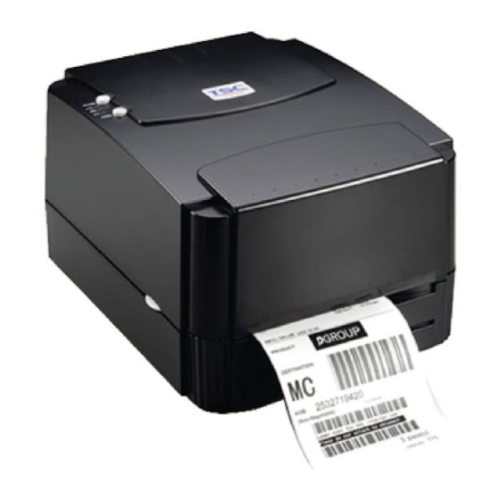
Thermal transfer/direct thermal bar code printer
Hide thumbs
Also See for TTP-244:
- User manual (29 pages) ,
- Programming manual (206 pages) ,
- Programming manual (434 pages)
Table of Contents
Advertisement
Advertisement
Table of Contents

Subscribe to Our Youtube Channel
Related Manuals for TSC TTP-244


Summary of Contents for TSC TTP-244
- Page 1 TTP-244 THERMAL TRANSFER / DIRECT THERMAL BAR CODE PRINTER USER’S MANUAL...
-
Page 3: Table Of Contents
CONTENTS PRODUCT INTRODUCTION ............2 1.1 Compliances..................... 2 GETTING STARTED ..............3 Unpacking and Inspection ................3 Equipment Checklist..................3 Printer Parts ....................4 External Label Roll Mount (Option) .............. 7 Buttons and Indicators.................. 8 SET UP ................... 9 Setting Up the Printer ................... 9 Loading Label and Tag Stock............... -
Page 4: Product Introduction
1. PRODUCT INTRODUCTION Thank you very much for purchasing TSC bar code printer. The attractive desktop printer delivers superior performance at an economical price. Both powerful and easy-to-use, this printer is your best choice among desktop direct thermal and thermal transfer label printers. This printer offers both thermal transfer and direct thermal printing, 32-bit RISC multi-tasking processor, print speed up to 4.0 inches per second features. -
Page 5: Getting Started
2. GETTING STARTED 2.1 Unpacking and Inspection The printer has been specially packaged to withstand damage in the shipping process. However, for fear that unexpected damage might occur, upon receiving the bar code printer, carefully inspect the package and the device. In case of evident damage, contact the carrier directly to specify the nature and extent of the damage. -
Page 6: Printer Parts
2.3 Printer Parts Figure 1. Top front view 1. Cover Release Button 2. PWR., ON-LINE and ERR. Indicators 3. PAUSE Button 4. FEED Button 5. Label Dispense Opening... - Page 7 Figure 2. Interior view 1. Printer Cover (in open position) 2. Label Supply Roll Spindle 3. Fixing Tabs 4. Ribbon Mechanism 5. Ribbon Supply Spindle 6. Ribbon Rewind Spindle 7. Printer Carriage Release Lever 8. Detachable Front Panel 9. PAUSE Button 10.
- Page 8 Figure 3. Rear view 1. Power On/Off Switch 2. Power Supply DC Jacket 3. RS-232C Interface Connector 4. USB Interface Connector 5. Label Insert Opening (For use with external media) 6. Centronics Interface Connector (Factory option)
-
Page 9: External Label Roll Mount (Option)
2.4 External Label Roll Mount (Option) Figure 4. External label roll mount... -
Page 10: Buttons And Indicators
2.5 Buttons and Indicators PWR. (POWER) Indicator The green PWR. indicator illuminates when the POWER switch is turned on. ON-LINE Indicator The green ON-LINE indicator illuminates when the printer is ready to print. When PAUSE button is pressed, the ON-LINE indicator flashes. ERR. -
Page 11: Set Up
3. SET UP 3.1 Setting Up the Printer 1. Place the printer on a flat, secure surface. 2. Make sure the POWER switch is off. 3. Connect the printer to the computer mainframe with the RS-232C or USB cable. 4. Plug the power cord into the power jacket at the rear of the printer, and then plug the power cord into a properly grounded receptable. - Page 12 Figure 5. Inserting label supply roll into label roll mount 1. Label Supply Roll Spindle 2. Label Roll Mount 3. Label Roll 4. Fixing Tabs...
- Page 13 Figure 6. Feed labels through adjustable label guide 1. Printer Carriage Release Lever 2. Platen 3. Label Media 4. Adjustable Label Guide...
-
Page 14: Ribbon Loading Instructions
3.3 Ribbon Loading Instructions 1. Place an empty paper core on the ribbon rewind spindle. 2. Install the ribbon on the ribbon supply spindle. 3. Disengage the printer carriage. 4. Pull the ribbon leader to the front from beneath the printer carriage. Attach the ribbon leader to the ribbon rewind paper core. - Page 15 Figure 9. Placement of ribbon supply roll 1. Printer Carriage Release Lever 2. Ribbon Supply Spindle 3. Ribbon Rewind Spindle 4. Thermal Transfer Ribbon...
- Page 16 Figure 10. Installation of label stock and thermal transfer ribbon...
-
Page 17: Install External Label Roll Mount (Option)
3.4 Install External Label Roll Mount (Option) Figure 11. Installation of external label roll mount 1. External Label Roll Mount 2. Label Supply Roll Spindle 3. External Label Feed Opening 4. Fixing Tabs... -
Page 18: Self Test
3.5 Self Test To initiate the self test mode, depress the FEED button while turning on the printer power. The printer will calibrate the label length. If the label gap is not detected within 7", the printer stops feeding labels and the media is treated as continuous paper. - Page 19 Note: The physical flash memory and DRAM on board is 2MB respectively. Due to system firmware will occupy 1MB, so total available flash memory space for downloads is 1024 K bytes. For DRAM, system and image buffer will occupy 1792 K bytes, so total available DRAM for downloads will be 256 K bytes.
-
Page 20: Dump Mode
3.6 Dump Mode After the self test, the printer enters the dump mode. In this mode, any characters sent from the host computer will be printed in two columns, as shown. The characters received will be shown in the first column, and their corresponding hexadecimal values, in the second. -
Page 21: Using Printer
4. USING PRINTER 4.1 Power-on Utilities There are three power-on utilities to set up and test hardware. These utilities are activated by pressing the FEED or PAUSE button and turning on the printer power simultaneously. The utilities are listed as below: 1. -
Page 22: Printer Initialization
4.1.3 Printer Initialization Printer initialization sets printer parameters to default values. And it will not clear downloaded files resident in flash memory. Parameter Default Value MILEAGE Automatic CHECK SUM Automatic SERIAL PORT 9600,N,8,1 CODE PAGE 437 (8 bit) COUNTRY CODE SPEED 2.0”/sec DENSITY... -
Page 23: Troubleshooting Guide
4.2 Troubleshooting Guide The following guide lists some of the most common problems that may be encountered when operating the bar code printer. If the printer still does not function after all suggested solutions have been invoked, please contact the Customer Service Department of your purchased reseller or distributor for assistance Problem... - Page 25 11F, No. 205, Sec. 3, Beishin Rd., Shindian City, , I-Lan County, Taiwan 268, R.O.C. Taipei 231, Taiwan, R.O.C.Taiwan 268, R.O.C. TEL: +886-3-990-6677 TEL: +886-2-8913-1308 FAX: +886-3-990-5577 FAX: +886-2-8913-1808 Web site: www.tscprinters.com E-mail: printer_sales@tscprinters.com TSC Auto ID Technology Co., Ltd. tech_support@tscprinters.com...
Need help?
Do you have a question about the TTP-244 and is the answer not in the manual?
Questions and answers