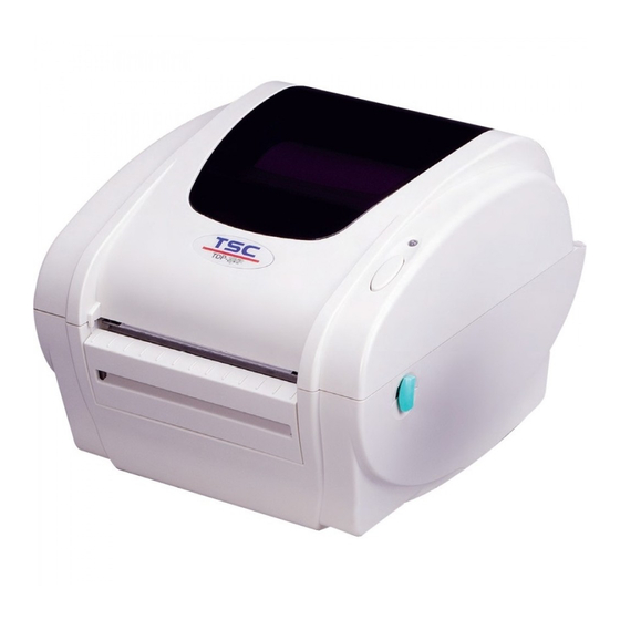
Page 3
LED Status ....................37 Print Quality ....................38 7. LED and Button Operation ..................39 7.1 LED ........................39 7.2 Button Operation ....................39 Revise History ....................... 43...
Information in this subject to change without notice and does not represent a commitment on the part of TSC Auto ID Technology Co., Ltd.. No part of this manual may be reproduced or transmitted in any form by any means, for any purpose other than the purchaser’s personal use, without the expressed written permission of T TSC Auto...
Page 5
CAUTION 1. HAZARDOUS MOVING PARTS IN CUTTER MODULE. KEEP FINGER AND OTHER BODY PARTS AWAY. 2. THE MAIN BOARD INCLUDES REAL TIME CLOCK FEATURE HAS LITHIUM BATTERY CR2032 INSTALLED. RISK OF EXPLOSION IF BATTERY IS REPLACED BY AN INCORRECT TYPE. 3.
Introduction Thank you for purchasing the TSC TDP-245/245 Plus/247/345 Series Direct Thermal Bar Code Printer. Although it is a compact desktop printer, it is reliable and with superior throughput performance. This printer provides direct thermal printing at user selectable speed of: 2.0, 3.0, 4.0, 5.0, 6.0 or 7.0 inches per second.
Page 7
Dealer option Peel off module assembly. Regular cutter (Guillotine cutter) Full cut: Paper thickness: 0.06~ 0.19mm, 500,000 cuts Paper thickness: 0.19mm 200,000 cuts Partial cut: Paper thickness: 0.06~0.12mm, 500,000 cuts Note: Except for the linerless cutter, all regular/heavy duty/care label cutters DO NOT cut on media with glue.
2.3 Printer Parts 2.3.1 Front View Clear Window Top Cover LED Indicator Feed Button Label Opening Top Cover Open Lever Backing Paper Opening Front Panel 2.3.2 Rear View 1. USB Interface 2. Centronics Interface 3. RS-232C DB-9 Interface 4. Power Jack 5.
3 Setup 3.1 Setting Up the Printer 1. Place the printer on a flat, secure surface. 2. Make sure the power switch is off. 3. Connect the printer to the computer with the Centronics or USB cable. 4 Plug the DC power cord into the power jack at the rear of the printer, and then plug the AC power cord into a properly grounded receptacle.
3.2 Loading Label Stock 1. Insert a 1” label spindle into a paper roll (If your paper core is 1 inch, remove the 1.5 inch core adapter from the fixing tab). Label Roll 1.5” Core Adapter Fixing Tab Printing Side Face up 1”...
Page 11
6. Close the printer cover slowly and make sure the cover locks levers securely. Note: Failure to securely close and lock the cover will result in poor print quality. Please refer to videos on TSC YouTube or driver CD.
Peel-Off Installation Assembly (Option) Open the top cover. Unscrew the 6 screws in the lower inner cover. Screws Screws Upside down the printer. Unscrew the 2 screws at the lower inner cover Remove the screw Remove the screw Remove the screw at memory card cover. Screw...
Page 13
Hold the lower cover and lift up the top cover opening levers to separate the lower inner cover from the lower cover. Lower inner cover Lower cover Thread the harness red connector through the cable hole at the front side of lower inner cover.
4. Adjust the black center-biased label guides by turning adjustment knob to fit the edge of the label backing. Adjustment Knob Roller Peel-off panel 5. Push the peel-off panel back to the printer. 6. Close the top cover. Note: Please refer to videos on TSC YouTube or driver CD.
3.5 External Label Roll Mount Installation (Option) 1. Attach an external label roll mount on the bottom of the printer. 2. Install a roll of label on the external label roll mount. Label External Label Roll Mount 3. Feed the label to the external label feed opening through the rear label guide. External Label Feed Opening Rear Label Guide...
3.6 Cutter Module Installation (Option) 1. Pull the top cover open levers to open the top cover. 2. Remove the front panel from the lower cover. 3. Remove 6 screws on the lower inner cover. Screws Screws 4. Upside down the printer. 5.
Page 19
7. Plug in the Cutter Driver IC at U14(TDP-245) / U30(TDP-245 Plus/TDP-247/TDP-345) socket on the main board. TDP-245 Model TDP-245 Plus/TDP-247/TDP-345 Model Cutter Driver IC Note: For Non-RoHS PCB, use cutter driver IC A3952SB For RoHS PCB, use cutter driver IC A3953SB 8.
Page 20
Niche 13. Ressemble the parts in the reverse order. 14. Close the top cover.
Label Guide Adjustment Knob Cutter Paper Opening Platen Cutter 5. Adjust the black center-biased label guides to fit edge of the label backing. 6. Close the top cover. Note: Please refer to videos on TSC YouTube or driver CD.
3.8 Diagnostic Tool The Diagnostic Utility is a toolbox that allows users to explore the printer’s settings and status; change printer settings; download graphics, fonts, and firmware; create printer bitmap fonts; and to send additional commands to the printer. Using this convenient tool, you can explore the printer status and settings and troubleshoot the printer.
3.8.2 Printer Function (Calibrate sensor, Ethernet setup, RTC setup………) 1. Select the PC interface connected with bar code printer. 2. Click the “Function” button to setting. 3. The detail functions in the Printer Function Group are listed as below. Function Description Calibrate the sensor specified in the Printer Calibrate Sensor...
3.9 Setting Ethernet by Diagnostic Utility (Option) The Diagnostic Utility is enclosed in the CD disk \Utilities directory. Users can use Diagnostic Tool to setup the Ethernet by RS-232, USB and Ethernet interfaces. The following contents will instruct users how to configure the Ethernet by these three interfaces.
3.9.2 Using RS-232 interface to setup Ethernet interface 1. Connect the computer and the printer with a RS-232 cable. 2. Turn on the printer power. 3. Start the Diagnostic Utility by double clicks on the icon. Note: This utility works with printer firmware V6.00 and later versions. 4.
3.9.3 Using Ethernet interface to setup Ethernet interface 1. Connect the computer and the printer to the LAN. 2. Turn on the printer power. 3. Start the Diagnostic Utility by double clicks on the icon. Note: This utility works with printer firmware V6.00 and later versions. 4.
Page 27
The default IP address is obtained by DHCP. To change the setting to static IP address, click “Static IP” radio button then enter the IP address, subnet mask and gateway. Click “Set IP” to take effect the settings. Users can also change the “Printer Name” by another model name in this fields then click “Set Printer Name”...
3.10. Install Memory Card 1. Upside down the printer. 2. Remove 1 screw and open the memory card cover. Memory Card Cover 3. Plug the memory card on main board. TDP-245 Model TDP-245 Plus/TDP-247/TDP-345 Model (Option) (SD card) 4. Revert the memory card cover. * Recommended SD card specification.
Set gap sensor as media sensor and calibrate the gap sensor Skip AUTO.BAS Note: Please refer to videos on TSC YouTube or driver CD. 4.1 Gap/Black Mark Sensor Calibration Gap/black mark sensor sensitivity should be calibrated at the following conditions: 1.
4.2 Gap/Black Mark Calibration, Self-test, Dump Mode While calibrate the gap/black mark sensor, printer will measure the label length, print the internal configuration (self-test) and then enter the dump mode. Please follow the steps as below. 1.Turn off the power switch. 2.
Page 32
Gap/black mark sensor sensitivity Numbers of download files Total & available memory space Self-test printout (with printer firmware V7.0 and later version) Model name F/W version Firmware checksum Printer S/N TSC configuration file System date System time Printed mileage (meter) Cutting counter...
Page 33
Print speed (inch/sec) Print darkness Label size (inch) Gap distance (inch) Gap/black mark sensor intension Code page Country code ZPL setting information Print darkness Print speed (inch/sec) Label size Control prefix Format prefix Delimiter prefix Printer power up motion Printer head close motion Note: ®...
Page 34
Note: 1. The physical flash memory for RoHS compliant version is 2MB Flash and 2MB DRAM (TDP-245 Model) / 8MB SDRAM (TDP-245 Plus/ TDP-247/ TDP-345 Model) 2. System occupies 960 KB in Flash memory so total flash memory space for user downloading is 1088 KB 3.
Dump mode Printer will enter dump mode after printing printer configuration. In the dump mode, all characters will be printed in 2 columns as following. The left side characters are received from your system and right side data are the corresponding hexadecimal value of the characters.
4.3 Printer Initialization Printer initialization is used to clear DRAM and restore printer settings to defaults. The only one exception is ribbon sensitivity, which will note be restored to default. Printer initialization is activated by the following procedures. 1. Turn off the power switch. 2.
4.4 Set Black Mark Sensor as Media Sensor and Calibrate the Black Mark Sensor Please follow the steps as below. 1. Turn off the power switch. 2. Hold on the button then turn on the power switch. 3. Release the button when LED turns green/amber after 5 green blinks. (Any green/amber will do during the 5 blinks).
5. Maintenance 5.1 Cleaning This session presents the clean tools and methods to maintain your printer. Please use one of following material to clean the printer. Cotton swab (Head cleaner pen) Lint-free cloth Vacuum / Blower brush ...
Page 39
cloth Brush or vacuum As needed Interior Note: Do not touch printer head by hand. If you touch it careless, please use ethanol to clean it. Please use 100% Ethenol. DO NOT use medical alcohol, which may damage the printer head. ...
Troubleshooting The following guide lists the most common problems that may be encountered when operating this bar code printer. If the printer still does not function after all suggested solutions have been invoked, please contact the Customer Service Department of your purchased reseller or distributor for assistance.
Print Quality Problem Possible Cause Recovery Procedure Check if interface cable is well Re-connect cable to interface. connected to the interface connector. The serial port cable pin configuration Please replace the cable with pin to is not pin to pin connected. pin connected.
LED and Button Operation This printer has one button and one three-color LED indicator. By indicating the LED with different color and pressing the button, printer can feed labels, pause the printing job, select and calibrate the media sensor, print printer self-test report, reset printer to defaults (initialization).
Page 43
Gap/Black Mark 1.Turn off the power switch. 2. Hold on the button then turn on the power switch. Sensor Calibration 3 Release the button when LED becomes red and blinking. (Any red will do during the 5 blinks). It will calibrate the gap/black mark sensor sensitivity. ...
Page 44
Printer 1. Turn off the power switch. 2. Hold on the button then turn on the power switch. Initialization 3. Release the button when LED turns green after 5 amber blinks. (Any green will do during the 5 blinks). The LED color will be changed as following: Amber ...
Page 45
Skip AUTO.BAS 1. Turn off printer power. 2. Press the FEED button and then turn on power. 3. Release the FEED button when LED becomes solid green. The LED color will be changed as following: Amber red (5 blinks) amber (5 blinks) green (5 blinks) ...
Need help?
Do you have a question about the TDP-244 Series and is the answer not in the manual?
Questions and answers