Table of Contents
Advertisement
Quick Links
www.ti.com
User's Guide
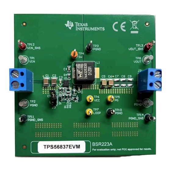
TPS56837 Buck Converter Evaluation Module
This user's guide contains information for the TPS56837 as well as support documentation for the
TPS56837EVM evaluation module. This user's guide includes the performance specifications, schematic, and
the bill of materials of the TPS56837EVM.
1
Introduction.............................................................................................................................................................................2
2 Performance Specification Summary...................................................................................................................................
3
Modifications...........................................................................................................................................................................2
3.1 Output Voltage Setpoint.....................................................................................................................................................
3.2 Mode Selection..................................................................................................................................................................
UVLO................................................................................................................................................................4
4 Test Setup and Results..........................................................................................................................................................
4.1 Input, Output Connections.................................................................................................................................................
4.2 Start-Up Procedure............................................................................................................................................................
4.3 Output Voltage Ripple........................................................................................................................................................
4.4
Start-Up..............................................................................................................................................................................6
4.5 Shutdown...........................................................................................................................................................................
Layout...........................................................................................................................................................................8
5.1 Layout................................................................................................................................................................................
6.1 Schematic........................................................................................................................................................................
6.2 List of Materials................................................................................................................................................................
6.3
Reference.........................................................................................................................................................................13
7 Revision History...................................................................................................................................................................
Trademarks
D-CAP3
™
and Eco-mode
All trademarks are the property of their respective owners.
SLVUCE1A - MARCH 2023 - REVISED AUGUST 2023
Submit Document Feedback
ABSTRACT
Table of Contents
Reference......................................................................................................................10
™
are trademarks of Texas Instruments.
Copyright © 2023 Texas Instruments Incorporated
Table of Contents
TPS56837 Buck Converter Evaluation Module
2
2
3
5
5
5
5
7
8
10
11
13
1
Advertisement
Table of Contents

Subscribe to Our Youtube Channel
Related Manuals for Texas Instruments TPS56837


Summary of Contents for Texas Instruments TPS56837
-
Page 1: Table Of Contents
TPS56837 Buck Converter Evaluation Module ABSTRACT This user's guide contains information for the TPS56837 as well as support documentation for the TPS56837EVM evaluation module. This user's guide includes the performance specifications, schematic, and the bill of materials of the TPS56837EVM. -
Page 2: Introduction
DC/DC converter. With the wide operating input voltage range of 4.5 V to 28 V, the TPS56837 is designed for systems powered from 12-V, 19-V, 24-V power-bus rails. The device supports up to 8-A continuous output current between 0.6 V and 13 V. -
Page 3: Mode Selection
Feed-forward Capacitor application report is helpful when experimenting with a feed-forward capacitor. 3.2 Mode Selection TPS56837 has a MODE pin that can offer six different options of overcurrent limit and switching frequency, as shown in Table 3-2. Table 3-2. MODE Pin Settings... -
Page 4: Adjustable Uvlo
) and R2 (R ). See the EN(TOP) EN(BOT) TPS56837 4.5-V to 28-V Input, 8-A Synchronous Buck Converter Data Sheet for detailed instructions for setting the external UVLO. TPS56837 Buck Converter Evaluation Module SLVUCE1A – MARCH 2023 – REVISED AUGUST 2023 Submit Document Feedback Copyright ©... -
Page 5: Test Setup And Results
4.3 Output Voltage Ripple The TPS56837EVM output voltage ripple waveforms are shown below. The output currents are as indicated. SLVUCE1A – MARCH 2023 – REVISED AUGUST 2023 TPS56837 Buck Converter Evaluation Module Submit Document Feedback Copyright © 2023 Texas Instruments Incorporated... -
Page 6: Start-Up
= 24 V, I = 8 A 4.4 Start-Up The TPS56837EVM start-up waveform relative to EN is shown below. TPS56837 Buck Converter Evaluation Module SLVUCE1A – MARCH 2023 – REVISED AUGUST 2023 Submit Document Feedback Copyright © 2023 Texas Instruments Incorporated... -
Page 7: Shutdown
SW = 20 V/div PG = 5 V/div 200 us/div Figure 4-4. TPS56837EVM Shutdown Relative to EN, I = 8 A SLVUCE1A – MARCH 2023 – REVISED AUGUST 2023 TPS56837 Buck Converter Evaluation Module Submit Document Feedback Copyright © 2023 Texas Instruments Incorporated... -
Page 8: Board Layout
5-7. The top layer contains the main power traces for VIN, VOUT, and ground. Also on the top layer are connections for the pins of the TPS56837 and a large area filled with power ground (PGND). Most of the signal traces are also located on the top side. - Page 9 Board Layout Figure 5-5. Middle Layer 1 Figure 5-6. Middle Layer 2 Figure 5-7. Bottom Layer SLVUCE1A – MARCH 2023 – REVISED AUGUST 2023 TPS56837 Buck Converter Evaluation Module Submit Document Feedback Copyright © 2023 Texas Instruments Incorporated...
-
Page 10: Schematic, List Of Materials, And Reference
6 Schematic, List of Materials, and Reference 6.1 Schematic Figure 6-1 is the schematic for the TPS56837EVM. Figure 6-1. TPS56837EVM Schematic Diagram TPS56837 Buck Converter Evaluation Module SLVUCE1A – MARCH 2023 – REVISED AUGUST 2023 Submit Document Feedback Copyright © 2023 Texas Instruments Incorporated... -
Page 11: List Of Materials
TP3, TP10, TP11, Test Point, Multipurpose, Black, TH 5011 Keystone TP14 Test Point, Multipurpose, Orange, TH 5013 Keystone SLVUCE1A – MARCH 2023 – REVISED AUGUST 2023 TPS56837 Buck Converter Evaluation Module Submit Document Feedback Copyright © 2023 Texas Instruments Incorporated... - Page 12 TPS56837RPAR Texas Instruments C7, C8, C9 CAP, CERM, 22 uF, 25 V, +/- 10%, X7R, 1210 GRM32ER71E226KE15L MuRata TPS56837 Buck Converter Evaluation Module SLVUCE1A – MARCH 2023 – REVISED AUGUST 2023 Submit Document Feedback Copyright © 2023 Texas Instruments Incorporated...
-
Page 13: Reference
Schematic, List of Materials, and Reference 6.3 Reference 1. Texas Instruments, TPS56837 4.5-V to 28-V Input, 8-A Synchronous Buck Converter data sheet 7 Revision History NOTE: Page numbers for previous revisions may differ from page numbers in the current version. - Page 14 STANDARD TERMS FOR EVALUATION MODULES Delivery: TI delivers TI evaluation boards, kits, or modules, including any accompanying demonstration software, components, and/or documentation which may be provided together or separately (collectively, an “EVM” or “EVMs”) to the User (“User”) in accordance with the terms set forth herein.
- Page 15 www.ti.com Regulatory Notices: 3.1 United States 3.1.1 Notice applicable to EVMs not FCC-Approved: FCC NOTICE: This kit is designed to allow product developers to evaluate electronic components, circuitry, or software associated with the kit to determine whether to incorporate such items in a finished product and software developers to write software applications for use with the end product.
- Page 16 www.ti.com Concernant les EVMs avec antennes détachables Conformément à la réglementation d'Industrie Canada, le présent émetteur radio peut fonctionner avec une antenne d'un type et d'un gain maximal (ou inférieur) approuvé pour l'émetteur par Industrie Canada. Dans le but de réduire les risques de brouillage radioélectrique à...
- Page 17 www.ti.com EVM Use Restrictions and Warnings: 4.1 EVMS ARE NOT FOR USE IN FUNCTIONAL SAFETY AND/OR SAFETY CRITICAL EVALUATIONS, INCLUDING BUT NOT LIMITED TO EVALUATIONS OF LIFE SUPPORT APPLICATIONS. 4.2 User must read and apply the user guide and other available documentation provided by TI regarding the EVM prior to handling or using the EVM, including without limitation any warning or restriction notices.
- Page 18 Notwithstanding the foregoing, any judgment may be enforced in any United States or foreign court, and TI may seek injunctive relief in any United States or foreign court. Mailing Address: Texas Instruments, Post Office Box 655303, Dallas, Texas 75265 Copyright © 2023, Texas Instruments Incorporated...
- Page 19 TI products. TI’s provision of these resources does not expand or otherwise alter TI’s applicable warranties or warranty disclaimers for TI products. TI objects to and rejects any additional or different terms you may have proposed. IMPORTANT NOTICE Mailing Address: Texas Instruments, Post Office Box 655303, Dallas, Texas 75265 Copyright © 2023, Texas Instruments Incorporated...
Need help?
Do you have a question about the TPS56837 and is the answer not in the manual?
Questions and answers