Table of Contents
Advertisement
Quick Links
www.ti.com
User's Guide
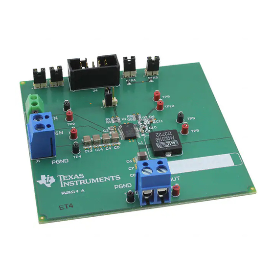
TPS56C20 Buck Converter Evaluation Module User's
Guide
This user's guide describes the characteristics, operation, and use of the TPS56C20EVM-614 evaluation module
(EVM). The document includes performance specifications, test setup and results, the printed-circuit board
(PCB) layout, a schematic, and a bill of materials (BOM).
1
Introduction.............................................................................................................................................................................3
2 Performance Specification Summary...................................................................................................................................
3
Modifications...........................................................................................................................................................................5
Point....................................................................................................................................................5
3.2 Output Voltage Set Point Using I2C Interface....................................................................................................................
3.3 Output Filter and Closed Loop Response..........................................................................................................................
4 Test Setup and Results..........................................................................................................................................................
4.1 Input/Output Connections..................................................................................................................................................
4.2 Start Up Procedure............................................................................................................................................................
4.3
Efficiency..........................................................................................................................................................................10
4.4 Load Regulation...............................................................................................................................................................
Regulation.................................................................................................................................................................11
4.6 Load Transient Response................................................................................................................................................
4.7 Output Voltage Ripple......................................................................................................................................................
4.8 Start Up............................................................................................................................................................................
Down........................................................................................................................................................................14
Layout.........................................................................................................................................................................15
5.1 Board
Layout....................................................................................................................................................................15
6 Schematic, Bill of Materials and Reference.......................................................................................................................
6.1 Schematic........................................................................................................................................................................
Materials.................................................................................................................................................................19
6.3
Reference.........................................................................................................................................................................19
7 Revision History...................................................................................................................................................................
Figure 3-1. USB2ANY Connection..............................................................................................................................................
Figure 3-3. EXT Power Settings..................................................................................................................................................
Figure 3-4. ALL VOUTS Control..................................................................................................................................................
Figure 4-3. TPS56C20EVM-614 Load Regulation.....................................................................................................................
Figure 4-4. TPS56C20EVM-614 Line Regulation......................................................................................................................
Figure 4-8. TPS56C20EVM-614 Start Up Relative to Enable...................................................................................................
Figure 4-10. TPS56C20EVM-614 Shut Down Relative to Enable.............................................................................................
Figure 5-1. Top Assembly..........................................................................................................................................................
Layer.................................................................................................................................................................16
Figure 5-3. Internal Layer 1.......................................................................................................................................................
SBAU227A - MARCH 2014 - REVISED JUNE 2021
Submit Document Feedback
ABSTRACT
Table of Contents
List of Figures
PANEL....................................................................................................................................7
Efficiency................................................................................................................................10
Current).........................................................................................................10
Response......................................................................................................12
Ripple............................................................................................................12
.........................................................................................................13
IN
....................................................................................................
IN
Copyright © 2021 Texas Instruments Incorporated
Table of Contents
4
5
8
9
9
9
11
12
12
13
18
18
19
6
7
8
11
11
13
14
14
15
16
1
Advertisement
Table of Contents

Subscribe to Our Youtube Channel
Related Manuals for Texas Instruments TPS56C20


Summary of Contents for Texas Instruments TPS56C20
-
Page 1: Table Of Contents
Figure 4-10. TPS56C20EVM-614 Shut Down Relative to Enable..................... Figure 5-1. Top Assembly................................Figure 5-2. Top Layer.................................16 Figure 5-3. Internal Layer 1............................... SBAU227A – MARCH 2014 – REVISED JUNE 2021 TPS56C20 Buck Converter Evaluation Module User's Guide Submit Document Feedback Copyright © 2021 Texas Instruments Incorporated... - Page 2 ® are registered trademarks of Microsoft Corporation. All trademarks are the property of their respective owners. TPS56C20 Buck Converter Evaluation Module User's Guide SBAU227A – MARCH 2014 – REVISED JUNE 2021 Submit Document Feedback Copyright © 2021 Texas Instruments Incorporated...
-
Page 3: Introduction
MOSFETs and the gate drive circuitry. The low drain-to-source on resistance of the MOSFETs allows the TPS56C20 to achieve high efficiencies and helps keep the junction temperature low at high output currents. The TPS56C20 DC/DC synchronous converter provides up to a 12-A output from an input voltage source of 4.5 V to 17 V. -
Page 4: Performance Specification Summary
Over current limit = 12 V 13.2 Output ripple voltage = 12 V, I = 12 A TPS56C20 Buck Converter Evaluation Module User's Guide SBAU227A – MARCH 2014 – REVISED JUNE 2021 Submit Document Feedback Copyright © 2021 Texas Instruments Incorporated... -
Page 5: Modifications
44 – 100 3.2 Output Voltage Set Point Using I2C Interface The engineer can change the TPS56C20 output voltage by using an I2C interface which can dynamically scale the output voltage in the range of 0.6 V to 1.87 V. -
Page 6: Figure 3-1. Usb2Any Connection
1. Go to Program Files and click on the TPS56X20 I2C TEST PANEL Application. The TPS56X20 I2C TEST PANEL will load as shown in Figure 3-2. TPS56C20 Buck Converter Evaluation Module User's Guide SBAU227A – MARCH 2014 – REVISED JUNE 2021 Submit Document Feedback Copyright © 2021 Texas Instruments Incorporated... -
Page 7: Figure 3-2. Tps56X20 I2C Test Panel
3. Go to the VOUTS control block and click on the ALL VOUTS control, illustrated in Figure 3-4. The drop down menu gives an option to select different VOUT. SBAU227A – MARCH 2014 – REVISED JUNE 2021 TPS56C20 Buck Converter Evaluation Module User's Guide Submit Document Feedback Copyright © 2021 Texas Instruments Incorporated... -
Page 8: Output Filter And Closed Loop Response
Observe that the Voltage at TP6 relative to TP7 is changed to the programmed VOUT value. 3.3 Output Filter and Closed Loop Response The TPS56C20 relies on the output filter characteristics to ensure stability of the control loop. The recommended output filter components for common output voltages are in Table 3-1. -
Page 9: Test Setup And Results
1. Make sure that the Enable jumper JP6 is closed to shunt EN to GND, disabling the output. 2. Apply the appropriate V voltage to PVIN (J1-1) and GND (J1-2). SBAU227A – MARCH 2014 – REVISED JUNE 2021 TPS56C20 Buck Converter Evaluation Module User's Guide Submit Document Feedback Copyright © 2021 Texas Instruments Incorporated... -
Page 10: Efficiency
TPS56C20EVM-614 at an ambient temperature of 25°C. Figure 4-1. TPS56C20EVM-614 Efficiency Figure 4-2. TPS56C20EVM-614 Efficiency (Low Current) TPS56C20 Buck Converter Evaluation Module User's Guide SBAU227A – MARCH 2014 – REVISED JUNE 2021 Submit Document Feedback... -
Page 11: Load Regulation
4.5 Line Regulation Figure 4-4 shows the line regulation for the TPS56C20EVM-614. Figure 4-4. TPS56C20EVM-614 Line Regulation SBAU227A – MARCH 2014 – REVISED JUNE 2021 TPS56C20 Buck Converter Evaluation Module User's Guide Submit Document Feedback Copyright © 2021 Texas Instruments Incorporated... -
Page 12: Load Transient Response
TPS56C20EVM-614 output voltage ripple. The output current is the rated full load of 12 A. Figure 4-6. TPS56C20EVM-614 Output Voltage Ripple TPS56C20 Buck Converter Evaluation Module User's Guide SBAU227A – MARCH 2014 – REVISED JUNE 2021 Submit Document Feedback... -
Page 13: Start Up
TPS56C20EVM-614 Start Up waveform is relative to Enable(EN). Figure 4-8. TPS56C20EVM-614 Start Up Relative to Enable SBAU227A – MARCH 2014 – REVISED JUNE 2021 TPS56C20 Buck Converter Evaluation Module User's Guide Submit Document Feedback Copyright © 2021 Texas Instruments Incorporated... -
Page 14: Shut Down
Figure 4-10 shows the TPS56C20EVM-614 Shut Down waveform relative to Enable(EN). Figure 4-10. TPS56C20EVM-614 Shut Down Relative to Enable TPS56C20 Buck Converter Evaluation Module User's Guide SBAU227A – MARCH 2014 – REVISED JUNE 2021 Submit Document Feedback Copyright © 2021 Texas Instruments Incorporated... -
Page 15: Board Layout
2 are filled with power ground. The bottom layer contains a few traces like the I2C connections and the output voltage trace to the J3 connector. Figure 5-1. Top Assembly SBAU227A – MARCH 2014 – REVISED JUNE 2021 TPS56C20 Buck Converter Evaluation Module User's Guide Submit Document Feedback Copyright © 2021 Texas Instruments Incorporated... -
Page 16: Figure 5-2. Top Layer
Board Layout www.ti.com Figure 5-2. Top Layer Figure 5-3. Internal Layer 1 TPS56C20 Buck Converter Evaluation Module User's Guide SBAU227A – MARCH 2014 – REVISED JUNE 2021 Submit Document Feedback Copyright © 2021 Texas Instruments Incorporated... -
Page 17: Figure 5-4. Internal Layer 2
Board Layout Figure 5-4. Internal Layer 2 Figure 5-5. Bottom Layer SBAU227A – MARCH 2014 – REVISED JUNE 2021 TPS56C20 Buck Converter Evaluation Module User's Guide Submit Document Feedback Copyright © 2021 Texas Instruments Incorporated... -
Page 18: Schematic, Bill Of Materials And Reference
NOTE: TPS56520: Wurth 1.5uH Inductor:74437346015 NOTE: TPS56720,TPS56920: Wurth 1.5uH Inductor:744311150 NOTE: TPS56C20: Wurth 1.5uH Inductor:744323150 Figure 6-1. TPS56C20EVM-614 Schematic Diagram TPS56C20 Buck Converter Evaluation Module User's Guide SBAU227A – MARCH 2014 – REVISED JUNE 2021 Submit Document Feedback Copyright © 2021 Texas Instruments Incorporated... -
Page 19: Bill Of Materials
Changes from Revision * (March 2014) to Revision A (May 2021) Page • Changed user's guide title..........................SBAU227A – MARCH 2014 – REVISED JUNE 2021 TPS56C20 Buck Converter Evaluation Module User's Guide Submit Document Feedback Copyright © 2021 Texas Instruments Incorporated... - Page 20 Revision History www.ti.com • Updated the numbering format for tables, figures, and cross-references throughout the document....3 TPS56C20 Buck Converter Evaluation Module User's Guide SBAU227A – MARCH 2014 – REVISED JUNE 2021 Submit Document Feedback Copyright © 2021 Texas Instruments Incorporated...
- Page 21 STANDARD TERMS FOR EVALUATION MODULES Delivery: TI delivers TI evaluation boards, kits, or modules, including any accompanying demonstration software, components, and/or documentation which may be provided together or separately (collectively, an “EVM” or “EVMs”) to the User (“User”) in accordance with the terms set forth herein.
- Page 22 www.ti.com Regulatory Notices: 3.1 United States 3.1.1 Notice applicable to EVMs not FCC-Approved: FCC NOTICE: This kit is designed to allow product developers to evaluate electronic components, circuitry, or software associated with the kit to determine whether to incorporate such items in a finished product and software developers to write software applications for use with the end product.
- Page 23 www.ti.com Concernant les EVMs avec antennes détachables Conformément à la réglementation d'Industrie Canada, le présent émetteur radio peut fonctionner avec une antenne d'un type et d'un gain maximal (ou inférieur) approuvé pour l'émetteur par Industrie Canada. Dans le but de réduire les risques de brouillage radioélectrique à...
- Page 24 www.ti.com EVM Use Restrictions and Warnings: 4.1 EVMS ARE NOT FOR USE IN FUNCTIONAL SAFETY AND/OR SAFETY CRITICAL EVALUATIONS, INCLUDING BUT NOT LIMITED TO EVALUATIONS OF LIFE SUPPORT APPLICATIONS. 4.2 User must read and apply the user guide and other available documentation provided by TI regarding the EVM prior to handling or using the EVM, including without limitation any warning or restriction notices.
- Page 25 Notwithstanding the foregoing, any judgment may be enforced in any United States or foreign court, and TI may seek injunctive relief in any United States or foreign court. Mailing Address: Texas Instruments, Post Office Box 655303, Dallas, Texas 75265 Copyright © 2019, Texas Instruments Incorporated...
- Page 26 TI products. TI’s provision of these resources does not expand or otherwise alter TI’s applicable warranties or warranty disclaimers for TI products.IMPORTANT NOTICE Mailing Address: Texas Instruments, Post Office Box 655303, Dallas, Texas 75265 Copyright © 2021, Texas Instruments Incorporated...
Need help?
Do you have a question about the TPS56C20 and is the answer not in the manual?
Questions and answers