Table of Contents
Advertisement
Quick Links
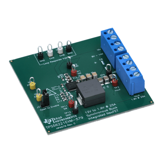
The Texas Instruments TPS56221EVM-579 evaluation module (EVM) is a synchronous buck converter
providing a fixed 1.2-V output at up to 25 A from a 12-V input bus. The EVM is designed to start up from a
single supply; so, no additional bias voltage is required for start-up. The module uses the TPS56221
High-Current, Synchronous Buck Converter with integrated MOSFETs.
The TPS56221 integrates TI's high-performance controller technology with TI's industry-leading MOSFET
technology in a standard QFN package to meet the demands of modern, high-current, space-constrained
applications.
..................................................................................................................
1
1.1
1.2
1.3
2
3
4
4.1
4.2
...................................................................................................................
5
5.1
5.2
5.3
5.4
5.5
5.6
6
6.1
6.2
6.3
6.4
6.5
7
8
1
TPS56221EVM-579 Schematic
2
3
4
5
6
7
8
9
SLVU446 - March 2011
Submit Documentation Feedback
TPS56221EVM-579 Evaluation Module
..........................................................................................................
.........................................................................................................
.............................................................................................................
...........................................................................................
..................................................................................
......................................................................................
............................................................................................
...........................................................................................................
...................................................................................................
...................................................................................
............................................................................................
..........................................................................................
..........................................................................................................
.......................................................................................
...........................................................................................
.......................................................................................................
....................................................................................
....................................................................................
List of Figures
...........................................................................................
........................................................................................
............................................................................
..............................................................................
© 2011, Texas Instruments Incorporated
Contents
...........................................................
..............................................................
....................................................
................................................................
.......................................................................
..................................................
......................................................................
................................................................
..................................................................
TPS56221EVM-579 Evaluation Module
User's Guide
SLVU446 - March 2011
3
3
3
3
3
4
5
5
5
6
6
7
9
9
10
10
10
10
11
11
12
12
13
19
4
8
8
9
10
11
11
12
12
1
Advertisement
Table of Contents

Related Manuals for Texas Instruments TPS56221EVM-579


Summary of Contents for Texas Instruments TPS56221EVM-579
-
Page 1: Table Of Contents
SLVU446 – March 2011 TPS56221EVM-579 Evaluation Module The Texas Instruments TPS56221EVM-579 evaluation module (EVM) is a synchronous buck converter providing a fixed 1.2-V output at up to 25 A from a 12-V input bus. The EVM is designed to start up from a single supply;... - Page 2 TPS56221EVM-579 Silk Screen, Viewed From Top ..............TPS56221EVM-579 Top Copper, Viewed From Top ............TPS56221EVM-579 Bottom Copper, Viewed From Bottom ............TPS56221EVM-579 Internal 1, X-Ray Viewed From Top ............TPS56221EVM-579 Internal 2, X-Ray Viewed From Top List of Tables ............TPS56221EVM-579 Electrical and Performance Specifications .....................
-
Page 3: Introduction
Introduction Description TPS56221EVM-579 is designed to use a regulated 12-V (8-V to 14-V) bus voltage to provide a regulated 1.2-V output at up to 25 A of load current. TPS56221EVM-579 is designed to demonstrate the TPS56221 high-current integrated, FET converter in a typical space-limited 12-V bus to low-voltage point-of-load application. -
Page 4: Tps56221Evm-579 Schematic
TPS56221EVM-579 Schematic www.ti.com TPS56221EVM-579 Schematic NOTE: For Reference Only, See Table Figure 1. TPS56221EVM-579 Schematic TPS56221EVM-579 Evaluation Module SLVU446 – March 2011 Submit Documentation Feedback © 2011, Texas Instruments Incorporated... -
Page 5: Connector And Test Point Descriptions
Connector and Test Point Descriptions Enable/SS Test Point – TP5 TPS56221EVM-579 is designed with a test point at the Enable/Soft-Start point (TP5). Shorting TP5 to GND connects the EN/SS pin to GND, discharges the soft-start capacitor, and disables the TPS56221 converter. -
Page 6: Test Setup
VIN to J1 The connection between the source voltage (VIN) and J1 of TPS56221EVM-579 can carry as much as 3.5 Adc of current. The minimum recommended wire size is AWG 16 with the total length of wire less than 2... -
Page 7: Equipment Setup
5.1.6 Thermal The TPS56221EVM-579 evaluation module includes components that can become hot to the touch when operating. Because this evaluation module is not enclosed to allow probing of circuit nodes, a small fan capable of 200-400 lfm is recommended to reduce component temperatures when operating. -
Page 8: Tps56221Evm-579 Recommended Test Setup
20mV / div 20MHz See Tip and Barrel Measurement for Vout ripple Figure 2. TPS56221EVM-579 Recommended Test Setup Metal Ground Barrel Probe Tip Tip and Barrel Vout ripple measurement Figure 3. Output Ripple Measurement – Tip and Barrel Using TP3 and TP4 TPS56221EVM-579 Evaluation Module SLVU446 –... -
Page 9: Start-Up/Shutdown Procedure
3. Set oscilloscope per Oscilloscope For Output Voltage Ripple measurement in Section 5.1.4. 4. Follow Steps 4 and 5 in Section 5.3 to power down. SLVU446 – March 2011 TPS56221EVM-579 Evaluation Module Submit Documentation Feedback © 2011, Texas Instruments Incorporated... -
Page 10: Control Loop Gain And Phase Measurement Procedure
TPS56221EVM-579 Test Data Figure 5 through Figure 8 present typical performance curves for the TPS56221EVM-579. Because actual performance data can be affected by measurement techniques and environmental variables, these curves are presented for reference and may differ from actual field measurements. Efficiency... -
Page 11: Line And Load Regulation
1.184 1.18 1.176 - Load Current - A LOAD Figure 6. TPS56221EVM-579 Output Voltage vs Load Current Output Voltage Ripple TPS56221EVM-579E3 Output Ripple Vin = 14 V, Vout = 1.2 V, Iout = 25 A Figure 7. TPS56221EVM-579 Output Voltage Ripple SLVU446 –... -
Page 12: Switch Node
Figure 8. TPS56221EVM-579 Switching Waveform Control Loop Bode Diagram Phase Gain -135 1000 f - Frequency - kHz Figure 9. TPS56221EVM-579 Gain and Phase vs Frequency TPS56221EVM-579 Evaluation Module SLVU446 – March 2011 Submit Documentation Feedback © 2011, Texas Instruments Incorporated... -
Page 13: Tps56221Evm-579 Assembly Drawings And Layout
Figure 15 show the design of the TPS56221EVM-579 printed circuit board. The EVM has been designed using a 4-Layer, 2oz copper-clad circuit board 2.5” x 2.5” with components on both sides of the PCB to allow the user to view, probe and evaluate the TPS56221 high current converter with integrated FET in a small form factor, high-current application. - Page 14 TPS56221EVM-579 Assembly Drawings and Layout www.ti.com Figure 11. TPS56221EVM-579 Silk Screen, Viewed From Top TPS56221EVM-579 Evaluation Module SLVU446 – March 2011 Submit Documentation Feedback © 2011, Texas Instruments Incorporated...
- Page 15 TPS56221EVM-579 Assembly Drawings and Layout www.ti.com Figure 12. TPS56221EVM-579 Top Copper, Viewed From Top SLVU446 – March 2011 TPS56221EVM-579 Evaluation Module Submit Documentation Feedback © 2011, Texas Instruments Incorporated...
- Page 16 TPS56221EVM-579 Assembly Drawings and Layout www.ti.com Figure 13. TPS56221EVM-579 Bottom Copper, Viewed From Bottom TPS56221EVM-579 Evaluation Module SLVU446 – March 2011 Submit Documentation Feedback © 2011, Texas Instruments Incorporated...
- Page 17 TPS56221EVM-579 Assembly Drawings and Layout www.ti.com Figure 14. TPS56221EVM-579 Internal 1, X-Ray Viewed From Top SLVU446 – March 2011 TPS56221EVM-579 Evaluation Module Submit Documentation Feedback © 2011, Texas Instruments Incorporated...
- Page 18 TPS56221EVM-579 Assembly Drawings and Layout www.ti.com Figure 15. TPS56221EVM-579 Internal 2, X-Ray Viewed From Top TPS56221EVM-579 Evaluation Module SLVU446 – March 2011 Submit Documentation Feedback © 2011, Texas Instruments Incorporated...
-
Page 19: Tps56221Evm-579 Bill Of Materials
TPS56221EVM-579 Bill of Materials www.ti.com TPS56221EVM-579 Bill of Materials Table 3. TPS56221EVM-579 Bill of Materials Count RefDes Value Description Size Part Number C1, C2, C3 22 µF Capacitor, Ceramic, 25V, X5R, 20% 1210 1.0 µF Capacitor, Ceramic, 25V, X5R, 20% 0805 4.7 µF... - Page 20 Evaluation Board/Kit Important Notice Texas Instruments (TI) provides the enclosed product(s) under the following conditions: This evaluation board/kit is intended for use for ENGINEERING DEVELOPMENT, DEMONSTRATION, OR EVALUATION PURPOSES ONLY and is not considered by TI to be a finished end-product fit for general consumer use. Persons handling the product(s) must have electronics training and observe good engineering practice standards.
- Page 21 IMPORTANT NOTICE Texas Instruments Incorporated and its subsidiaries (TI) reserve the right to make corrections, modifications, enhancements, improvements, and other changes to its products and services at any time and to discontinue any product or service without notice. Customers should obtain the latest relevant information before placing orders and should verify that such information is current and complete.
Need help?
Do you have a question about the TPS56221EVM-579 and is the answer not in the manual?
Questions and answers