Interacoustics AT235 Instructions For Use Manual
Hide thumbs
Also See for AT235:
- Instructions for use manual (1373 pages) ,
- Service manual (54 pages) ,
- Additional information (45 pages)
Table of Contents
Advertisement
Quick Links
Advertisement
Table of Contents

Related Manuals for Interacoustics AT235


Summary of Contents for Interacoustics AT235
- Page 1 Science made smarter Instructions for Use - US AT235...
-
Page 3: Table Of Contents
License ..........................12 2.11 About Diagnostic Suite ......................13 Operating Instructions .........................15 2.12 Handling and selection of ear tips.....................16 2.13 Switching the AT235 on and off....................16 2.14 Probe Status...........................17 2.15 Use of standard and clinical probe system ................18 2.16 AT235 Stand-alone operation ....................18 2.16.1... - Page 4 Maintenance..........................39 General Maintenanc e Procedures ....................39 General Maintenanc e Procedures ....................40 Cleaning the Probe Tip ......................41 Concerning Repair ........................42 Warranty ..........................42 Periodic calibration........................43 Technical Specifications ......................45 Calibration Properties ......................47 Ref erenc e equivalent threshold values f or transducers ..............51 Pin Assignments ........................52 Electromagnetic Compatibility (EMC) ..................53...
-
Page 5: Introduction
1.2 Intended Use The AT235 is an automatic impedance audiometer with built-in screening audiometry suited f or screening, as well as diagnostic work. Neonatal screening programs will particularly appreciate the presence of high probe tone tympanometry, allowing more reliable tympanometric results in neonates. -
Page 6: Product Description
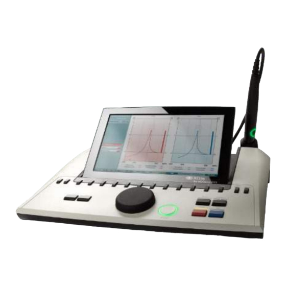
1.4 Product description The AT235 consist of the f ollowing parts: Included Parts AT235 instrument Clinical Probe System Diagnostic Probe System 1, 2 Power supply unit UES65-240250SPA3 Contralateral headphone Daily check cavity CAT50 (option) DD65v2 Audiometric headset Patient Response (Option) -
Page 7: About Warnings And Cautions
1.5 About warnings and cautions Throughout this manual the f ollowing meaning of warnings, cautions and notices are used: WARNING indicates a hazardous situation which, if not avoided, could result in death or serious injury. CAUTION, used with the saf ety alert symbol, indicates a hazardous situation which, if not avoided, could result in minor or moderate injury. - Page 8 D-0128073-C – 2022/05 AT23 5 - Instructions for Use - US Page 4...
-
Page 9: Unpacking And Installation
Keep carton for future shipment AT235 comes in its own shipping carton, which is specially designed f or the AT235. Please keep this carton. It will be needed if the instrument has to be returned f or service. -
Page 10: Markings
This symbol indicates that when the end-user wishes to discard this product, it must be sent to separate collection f acilities f or recovery and recycling. The CE-mark in combination with MD symbol indicates that Interacoustics A/S meets the requirements of the Medical Device Regulation (EU) 2017/745. -
Page 11: Important Safety Instructions
Batteries may explode or cause burns, if disassembled, crushed or exposed to f ire or high temperatures. Do not short-circuit. 7. No modif ication of this equipment is allowed without Interacoustics authorization. Interacoustics will make available on request circuit diagrams, component part lists, descriptions, calibration instructions, or other inf ormation that will assist service personnel to repair those parts of this audiometer that are designated by the Interacoustics as repairable by service personnel. -
Page 12: Malfunction
4. Use of accessories, transducers and cables other than specif ied, with the exception of transducers and cables sold by Interacoustics or representatives may result in increased emission or decreased immunity of the equipment. For list of accessories, transducers and cables that f ulf ils the requirements please ref er to section 5.4... -
Page 13: Connections
2.5 Connections Probe Dedicated probe connection LAN (Not used) USB B For printer, mouse, keyboard, Memory stick USB A For PC connection HDMI For external monitor or projector In 24 V Use only specif ied power supply unit UES65-240250SPA3 type Trigger in / out Cochlear implant trigger option Pat. -
Page 14: Changing Probe System
2.7 Changing probe system Change between the standard and clinical probe as f ollows: 1. Locate the probe connection on the back of the unit. 2. Open the 2 locks by pushing them to the sides. 3. Swap to the other probe system. 4. -
Page 15: Safety Precautions To Take When Connecting The At235
Use updated antivirus and f irewall and anti-malware sof tware Implement appropriate backup policy Implement appropriate log retention policy Please f ollow instructions below. Fig 1. AT235 used with the medically approved power supply UES65-240250SPA3. Medical power supply Mains outlet AT235 alone D-0128073-C –... -
Page 16: License
Fig. 2. AT235 used with, a medically approved saf ety transf ormer and a wired connection to a PC. AT235 Medical power supply Medically approved safety transformer Mains outlet PC power supply Printer Fig. 3. AT235 used with the medically UES65 and printout with HM-E300/MPT-III printer. -
Page 17: About Diagnostic Suite
2.11 About Diagnostic Suite Should you go to Menu > Help > About then you will see the below window. This is the area of the sof tware where you can manage license keys and check your Suite, Firmware and Build Versions. Also, in this window you will f ind the Checksum section which is a f eature designed to help you identif y the integrity of the sof tware. - Page 18 D-0128073-C – 2022/05 AT23 5 - Instructions for Use - US Page 14...
-
Page 19: Operating Instructions
Calm and stable positioning while testing is pref erred f or optimal accuracy. 2. The AT235 should be operated in a quiet environment, so that measurements are not inf luenced by outside acoustic noises. This may be determined by an appropriately skilled person trained in acoustics. -
Page 20: Handling And Selection Of Ear Tips
For more stable testing, we recommend using an extension cord with a mushroom shaped ear tip. Make sure that this ear tip inserts completely into the ear canal. Mushroom shaped ear tips allow you to test ‘hands f ree’ f rom the AT235. This reduces the chance of contact noise disturbing the measurement. -
Page 21: Probe Status
White The probe has just been attached. Probe status is unknown. If the probe light stays white in any other situation the AT235 may need to be switched of f and back on again to regain proper probe status. Blinking AT235 is pausing and/or an interaction is expected. -
Page 22: Use Of Standard And Clinical Probe System
2.16 AT235 Stand-alone operation 2.16.1 AT235 Stand-alone operation panel Name Description Turns the AT235 ON and OFF. Shif t Shif t is used to access secondary f unctions of the other keys. Setup Hold down Setup and use the wheel (19) to select the desired Setup menu then let go of the Setup button to open it. -
Page 23: Startup
Selects right ear f or testing. Lef t Selects lef t ear f or testing. 2.16.2 Startup The AT235 will always load the last used tympanometry protocol as a starting point. D-0128073-C – 2022/05 AT23 5 - Instructions for Use - US Page 19... -
Page 24: Instrument Settings - Language, Printer, Date & Time, Etc
For changing the operation language of the system hold the Language button (6) while using the wheel (19) to selecting the language of your choice. The AT235 needs to be restarted f or the change to be ef f ectuated. -
Page 25: Test And Module Selection
2.16.5 Tympanometry test screens Af ter startup the AT235 will have selected the last used impedance protocol and will be ready to start a test. The screen now shown we ref er to as the test screen. The f ollowing paragraphs describe which inf ormation and f unctionalities are f ound on the tympanogram, ref lex and audiometry test screens. -
Page 26: Tymp Test Screen
2.16.5.1 Tymp test screen Probe status showing the color corresponding to the probe light as described in paragraph 3.3. It shows the labels: in ear, out of ear, leaking or blocked Probe tone f requency. The current pressure is indicated in daPa. The open triangle shows the current pressure. - Page 27 Pressing Scale allows changing the scale of the compliance axis in the tympanogram. Pressing Compensated allows activating or deactivating the compensation of the tympanogram according to the estimated ear canal volume. Pressing Y allows toggling between viewing the so called Y, B or G tympanogram.
-
Page 28: Reflex Test Screen
2.16.5.2 Reflex test screen The upper bar of the sof t keys indicates the f unction in auto mode, while the lower bar shows the f unction f or the sof t keys in manual mode. Activating manual mode in the ref lex test allows single ref lex measurements at a time and optionally the pressure at which the ref lex is measured can be manually set (see T). - Page 29 Pressing the arrow down button moves the ref lex selection to the next ref lex row. Moving the selection sideways is done with the wheel (19). Pressing Change Status toggles the status of the currently selected ref lex (Q). Green indicates that a ref lex is present while red/blue indicates that the ref lex is not present.
-
Page 30: Audiometry Test Screen
The measurement type (HL, MCL, UCL or Tinnitus is shown) as well as the presentation type (tone or pediatric noise) and the test f requency is shown. For clarity second channel inf ormation is shown, although the AT235 cannot contain licenses to use this second channel. -
Page 31: Start And Stop Of A Tympanometric Test
2.16.7 Start and stop of a tympanometric test Af ter startup the AT235 is ready to automatically start a measurement as soon as it detects that the probe is in the ear. When the probe is in the ear the test can be manually stopped (or paused) and again started by pressing the “Start/stop”... -
Page 32: Save
2.16.8 Save Press “Save” (17) to enter the save screen. Use the wheel (19) to select a client f rom the list and press “Enter” (22) or press “Save” (13) to conf irm that data must be saved f or the selected client. Bef ore saving the session, you may edit an existing client or create a new client by pressing the Edit button (5) or the New button (6). -
Page 33: View Historical Sessions
2.16.9 View historical sessions Press the “Clients” button (16) and use the wheel (19) to scroll between clients. Select the client by pressing the “Select” button (13) and a list of available sessions will appear. Use again the wheel (19) to highlight the session that needs to be selected. -
Page 34: Operating In Sync Mode (Only With Diagnostic Suite)
(as shown below). The crash report provides inf ormation to Interacoustics about the error message and extra inf ormation can be added by the user outlining what they were doing bef ore the crash occurred to assist in f ixing the problem. A screen shot of the sof tware can also be sent. -
Page 35: Instrument Setup
Select Menu | Setup | Suite setup… to open general suite settings. Important: Both at the AUD module and the IMP module, please be sure to select the “AT235 (version 3)” (and not “AT235”, which ref ers to the old version). -
Page 36: Using Sync Mode
2.18 Using Sync Mode Sync mode allows f or a one click data transf er. When pressing Save Session on the instrument, the session will automatically be transf erred to the Diagnostic Suite. Start the suite with device connected. 2.18.1 Using IMP Sync The f ollowing operations are available on the IMP tab of the Diagnostic Suite: Menu provides access to Setup, Print, Edit and Help (ref er to the Additional Inf ormation document f or more details about the menu... - Page 37 List of Defined Protocols allows viewing which protocol was used f or historic sessions. Temporary setup allows viewing the used settings f or historic sessions. List of historical sessions accesses historical sessions f or review or the Current Session. Go to current session takes you back to the current session. Report editor button opens a separate window f or adding and saving notes to the current session.
-
Page 38: Using Aud Sync
2.18.2 Using AUD Sync The f ollowing operations are available on the AUD tab of the Diagnostic Suite: Menu provides access to Print, Edit, View, Tests, Setup and Help (ref er to the Additional Inf ormation document f or more details about the menu items). - Page 39 Transfer allowing updating the PC screen with data currently available in the audiometry module of the AT235. The counseling overlays can be activated on a separate patient monitor. Phonemes, sound examples, speech banana, a severity indication and maximum testable values are available as overlay.
-
Page 40: Sync Mode
2.18.3 SYNC Mode If there are several sessions stored on the AT235 (under one or more patients) then the Sync tab is supposed to be used. The screen shot below shows the Diagnostic Suite with the SYNC tab open (underneath the AUD and IMP tabs in the upper right corner). -
Page 41: Client Upload
AT235 memory. The internal AT235 memory can hold up to 500 clients and 50.000 sessions. • On the right side the clients currently stored on the internal AT235 memory (hardware) is down. It is possible to remove all clients f or individual clients using the “Remove all” or “Remove” buttons. 2.18.5 Session download The f ollowing screen shot shows the session download screen: When pressing the “Find client”... - Page 42 D-0128073-C – 2022/05 AT23 5 - Instructions for Use - US Page 38...
-
Page 43: Maintenance
4 Maintenance 4.1 General Maintenance Procedures Routine checking (subjective tests) It is recommended that routine check procedures are carried out weekly in f ull on all equipment in use. Check 1-9 outlined below should be f ollowed on the equipment on each day of use. General The purpose of routine checking is to ensure that the equipment is working properly, that its calibration has not noticeably changed, and that its transducers and connections are f ree f rom any def ect that might... -
Page 44: General Maintenance Procedures
Check that attenuators do attenuate the signals over their f ull range and that attenuators which are intended to be operated while a tone is being delivered are f ree f rom electrical or mechanical noise Check that controls operate silently and that no noise radiated f rom the audiometer is audible at the subject’s position. -
Page 45: Cleaning The Probe Tip
4.3 Cleaning the Probe Tip Diagnostic probe Clinical probe Step 1: Unscrew the probe cap and remove the probe tip. Step 2: Thread the stif f end of the cleaning brush into one of the tubes f rom inside. Pull the cleaning f loss completely through the probe tip tube. -
Page 46: Concerning Repair
INTERACOUS TICS guarantees that: • The AT235 is f ree f rom def ects in material and workmanship under normal use and service f or a period of 12 months f rom the date of delivery by Interacoustics to the f irst purchaser •... -
Page 47: Periodic Calibration
4.6 Periodic calibration Minimum periodic calibration requirements: Minimum calibration interval of once (annually) per 12-month period. Records of all calibrations should be kept on f ile. Recalibration should be perf ormed af ter: A specif ied time period has elapsed (12-month period maximum, annually). When a specif ied usage (operating hours) has elapsed. - Page 48 D-0128073-C – 2022/05 AT23 5 - Instructions for Use - US Page 44...
-
Page 49: Technical Specifications
5 Technical Specifications General Medical CE-mark: The CE-mark in combination with MD symbol indicates that Interacoustics A/S meets the requirements of the Medical Device Regulation (EU) 2017/745. Approval of the quality system is made by TÜV – identif ication no. 0123. - Page 50 Reflex Functions Signal sources: Tone - Contra, Ref lex: 250, 500, 1000, 2000, 3000, 4000, 6000, 8000 Hz, Wide Band, High and Low pass Tone - Ipsi, Ref lex: 500, 1000, 2000, 3000, 4000 Hz wide band, high and low pass. NB noise –...
-
Page 51: Calibration Properties
5.1 Calibration Properties Calibrated Transducers: Contralateral Telephonics TDH39/DD45 with a static f orce of 4.5N Earphone: ±0.5N Probe system: Ipsilateral Earphone: is integrated in the probe system Probe f requency transmitter and receiver and pressure transducer is integrated in the probe system Accuracy: General Generally, the instrument is made and calibrated to be... - Page 52 Contralateral Earphone Pure tone: ISO 389-1 f or TDH39 and ISO 389-9 f or IP30. Wide Band noise (WB): Interacoustics Standard Spectral properties: As “Broad band noise” specif ied in IEC 60645-5, but with 500 Hz as lower cut-of f f requency.
- Page 53 11.7 3000 -0.8 -0.5 31 (3150 Hz) 4000 -1.6 -0.8 6000 15.5 20.5 3 26 (6300 Hz) 8000 *All f igures in bold are Interacoustics Standard values. D-0128073-C – 2022/05 AT23 5 - Instructions for Use - US Page 49...
- Page 54 The perf ormance and specif ications of the instrument can only be guaranteed if it is subject to technical maintenance at least once per year. This should be carried out by a workshop authorized by Interacoustics. Interacoustics puts diagrams and service manuals at the disposal of authorized service companies.
-
Page 55: Reference Equivalent Threshold Values For Transducers
5.2 Reference equivalent threshold values for transducers AT235 Maximums IMP TDH39 DD65 v2 IP30 IPSI DD45 Center Reading Reading Reading Reading Reading Freq. Tone Tone Tone Tone Tone [Hz] [dB HL] [dB HL] [dB HL] [dB HL] [dB HL] [dB HL]... -
Page 56: Pin Assignments
5.3 Pin Assignments Inputs Connector type Electrical properties Patient response Jack6.3mm Handheld switch: 3V through 10K is f orced to ground Pin 1: GND when activated Pin 2: Signal Outputs: Phones, Lef t Jack, 6.3mm Voltage: Up to 3V rms. by 10 ohm load Min. -
Page 57: Electromagnetic Compatibility (Emc)
EMC inf ormation presented in this chapter. The AT235 has been tested f or EMC emissions and immunity as a standalone AT235. Do not use the AT235 adjacent to or stacked with other electronic equipment. If adjacent or stacked use is necessary, the user should verif y normal operation in the conf iguration. - Page 58 Guidance and Manufacturer’s Declaration - Electromagnetic Immunity The AT235 is intended f or use in the electromagnetic environment specif ied below. The customer or the user of the AT235 should assure that it is used in such an environment. Immunity Test...
- Page 59 Guidance and manufacturer’s declaration — electromagnetic immunity The AT235 is intended f or use in the electromagnetic environment specif ied below. The customer or the user of the AT235 should assure that it is used in such an environment, Immunity test...
- Page 60 To ensure compliance with the EMC requirements as specif ied in IEC 60601-1-2, it is essential to use only the f ollowing accessories: ITEM MANUFACTURER MODEL Power supply unit UE65 Interacoustics UE65-240250SPA Clinical Probe Interacoustics Clinical probe system 1077 Diagnostic prob...