Table of Contents
Advertisement
Advertisement
Table of Contents

Related Manuals for barfield TT1200A


Summary of Contents for barfield TT1200A
- Page 1 TT1200A & OH58D Turbine Temperature Test Set USER INSTRUCTION MANUAL M/N: TT1200A, P/N: 101-00930 M/N: OH58D, P/N: 101-00930-OH58D Doc P/N: 56-101-00930 Revision H June 3, 2022 ______________________________________ Copyright © 2022 Barfield Inc. All Rights Reserved...
- Page 2 Barfield Inc. Confidential and Proprietary Information. This document and all the information contained herein is the sole property of Barfield Inc. No intellectual property rights are granted by the delivery of this document or the disclosure of its content.
- Page 3 Users are requested to notify the manufacturer of any discrepancy, omission, or error found in this manual. Inquiries should include specific questions and reference the publication title, number, chapter, page, figure, paragraph, and effective date. Please send comments to: TECHNICAL CUSTOMER SUPPORT - GSTE BARFIELD, INC. P.O. BOX 025367 MIAMI, FL 33102-5367 Telephone (305) 894-5400...
- Page 4 The manufacturer of this equipment does not recommend the user to attempt any maintenance or repair. In case of malfunction, contact the manufacturer to obtain the list of approved repair facilities worldwide, ensuring that this equipment will be serviced using proper procedures and certified instruments. BARFIELD PRODUCT SUPPORT DIVISION Telephone (305) 894-5400 Shipping Address: (800) 321-1039 Barfield, Inc.
- Page 5 Updated recertification to include 101- 260-00914 May 21, 2012 00930-OH58D. 260-00914 September 25, 2014 Updated Barfield logo & warranty info. Removal of CE label on Figure 1. Figure 2 updated. Revision of General Description, 260-01254 April 20, 2020 item 10. Document reformatted. Minor grammar revisions.
-
Page 6: Table Of Contents
TABLE OF CONTENTS Contact Information Maintenance and Repair Information Revision Record Table of Contents List of Figures List of Tables PAGE INTRODUCTION ........................viii PUBLICATION BREAKDOWN ....................viii INFORMATION PROVIDED WITH THE TEST SET ..............viii RECERTIFICATION ........................ix CHAPTER 1: GENERAL ......................1 INTENDED USE ......................... - Page 7 Figure 3 Limited One Year Warranty ....................x Figure 4 TT1200A Test Set ........................1 Figure 5 TT1200A Front Panel & Switches ..................5 Figure 6 Power Up Message Display Sequence .................. 9 Figure 7 Display Menu Flowchart ......................9...
-
Page 8: Introduction
INTRODUCTION 1. PUBLICATION BREAKDOWN A. This user instruction manual establishes the standards of operation for the TT1200A Turbine Temperature Test Set. Its purpose is to provide sufficient information for the personnel unfamiliar with this Tester to understand this equipment, identify its parts, and operate it in accordance with proper procedures, operating techniques, precautions, and limitations. -
Page 9: Recertification
This certificate confirms that the unit performed according to its design specifications. C. The Owner’s Warranty Registration card (refer to Figure 2) is to be completed by the owner and returned to Barfield, Inc. within ten (10) days of purchase to ensure automatic update of printed matter and validation of warranty. -
Page 10: Figure 3 Limited One Year Warranty
Figure 3 Limited One Year Warranty 56-101-00930 Revision H Page x... -
Page 11: Chapter 1: General
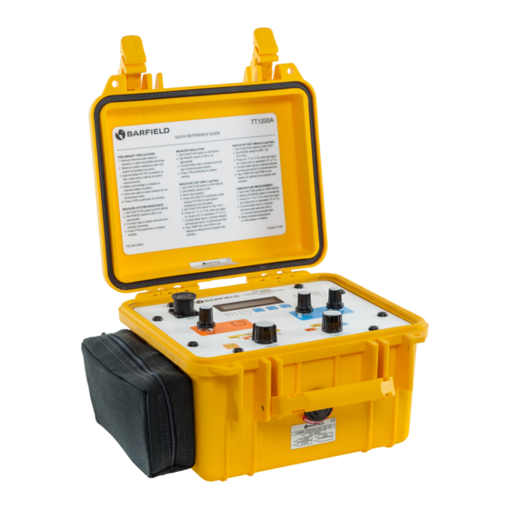
A. This publication contains the description and the operating procedures for: 1. TT1200A, Digital Turbine Temperature Test Set, P/N 101-00930 2. OH58D, Digital Turbine Temperature Test Set, P/N 101-00930-OH58D The TT1200A is specifically designed to test and calibrate Chromel - Alumel (CH - AL) temperature indicating systems. 2. DESCRIPTION Note: It is recommended that the user read this manual through its entirety to become familiar with the TT1200A Test Set and use the placard instructions as a quick reference only. - Page 12 The lid contains a placard of short operating instructions for the experienced technician. 10. Auto Detection of Cable: At power up, the TT1200A looks to see if the Standard Cable leads are connected to the panel’s TEST receptacle and displays the prompt “TEST CABLE?” if no cable is detected.
-
Page 13: Specifications
3. SPECIFICATIONS A. Physical Characteristics Size (H, W, L) 7.0 in. (17.8 cm), 11.0 in. (27.9 cm), 10.0 in. (25.4 cm) Weight 7.3 lbs. (3.3 kg) Table 1 Physical Characteristics B. Temperature K (CH – AL Thermocouple) Type Range -25°C to +1200°C (certified) -50°C to +1372°C (extended) Accuracy Typical measurement error at 77°F (25°C) ambient: less... -
Page 14: Capabilities
4. CAPABILITIES A. Measures and displays resistance of thermocouples, thermocouple rings and system lead circuits. B. Measures and displays insulation resistance of system wiring and other components. C. Simulates CH - AL thermocouples with or without simulated system lead resistance. D. -
Page 15: Chapter 2: Operation
14 15 Figure 5 TT1200A Front Panel & Switches 1. The PWR (power) pushbutton, when pressed, applies power to the TT1200A and begins the initialization process. 2. The BKLT (backlight) pushbutton, when pressed, provides a backlight to the LCD to improve readability under dim lighting conditions. - Page 16 0 Ω system resistance for the IND TEST function. 7. The PTM (Press To Measure) button, when pressed, activates the TT1200A excitation and measuring processes (when the FUNCTION switch is set to the RES MEAS or INS MEAS position).
-
Page 17: General Operating Instructions
Test Set. A. Protective Circuits Although the TT1200A has input protection, do not connect the test set to an energized circuit. B. Battery Installation and Verification 1. Remove the covers from the battery holders located on the right side of the case. Lift the left side of the TT1200A so that the batteries slide out. -
Page 18: Power Up (Initialization)
Note: The TT1200A replaces the message “PTS” with “SET” on the display. 3. POWER UP (INITIALIZATION) A. At power up, the TT1200A displays a series of informational messages (refer to Figure 5), including the unit’s software version (Ver ##.##.##.X); the available battery power percentage (Battery ###%) and the calibration due date (Cal. -
Page 19: Menu Displays
Figure 6 Power Up Message Display Sequence 4. MENU DISPLAYS A. Once the MENU button is pressed, the user may use the mV ( ↑ ) or the °F ( ↓ ) soft keys to scroll through the message display and option menus as shown (refer to Figure 7): Figure 7 Display Menu Flowchart 1. - Page 20 3. Cal Due mm/yyyy The display shows the month and year when calibration is due. 4. Auto Off This feature allows the user to set a time period for the unit to automatically turn off when not in use. To activate the feature at the Auto ± display, press ENT (°C). Use the mV or °F keys to set 5-minute increments (up to 60 minutes).
-
Page 21: Chapter 3: Test Procedures
CHAPTER 3: TEST PROCEDURES 1. MOVING COIL TYPE INDICATOR TEST PROCEDURES A. System Lead Resistance Test Procedure 1. Access the aircraft system temperature indicator 2. Disconnect thermocouple leads from the indicator. 3. Connect the standard leads to the Test Set’s TEST connector. 4. - Page 22 8. The red clip connects to the Chromel lead and the black clip to Alumel lead. 9. Press and release the PTM pushbutton. 10. The display shows resistance in Ω with 0.01 Ω resolution. 11. If display reads “OUT OF RANGE”, the resistance is greater than 199.99 Ω, or there is an open circuit.
- Page 23 RED clip. 13. Set the TEMP ADJ control knob for the desired test temperature as displayed on the TT1200A display indicator. It may be necessary to use the FINE control to achieve the exact settings. 14. Compare the readings of indicator under test with the TT1200A readings.
-
Page 24: Potentiometric Or Servo-Type Indicator Test Procedure
1. Disconnect the aircraft power to indicator (refer to the AMM). 2. Disconnect the electrical connector at the rear of indicator. 3. Connect the TT1200A leads to probe pins sized to fit the Chromel and Alumel pin sockets of the aircraft plug removed from indicator. - Page 25 7. Press the mV, °F or °C key to select units of measurements. 8. Connect the TT1200A leads to probe pins sized to fit the Chromel and Alumel pin sockets of the aircraft plug removed from indicator. For the P/N 101-00930-OH58D connect the Green clip to aircraft chassis ground.
-
Page 26: Chapter 4: Receiving, Shipping & Storage
CHAPTER 4: RECEIVING, SHIPPING & STORAGE 1. RECEIVING A. No special unpacking procedures are necessary. It is recommended that factory shipping container and packing materials be retained should it become necessary, for any reason, to reship the Test Set. It is also recommended that the Test Set be carefully inspected for damage. If damaged, immediately notify both the carrier and manufacturer.
Need help?
Do you have a question about the TT1200A and is the answer not in the manual?
Questions and answers