
Subscribe to Our Youtube Channel
Related Manuals for barfield TT1000A


Summary of Contents for barfield TT1000A
- Page 1 TT1000A Turbine Temperature Test Set USER INSTRUCTION MANUAL M/N: TT1000A, P/N: 101-00901 Doc P/N: 56-101-00901 Revision F March 17, 2022 ______________________________________ Copyright © 2022. Barfield Inc. All Rights Reserved...
- Page 2 Barfield Inc. Confidential and Proprietary Information. This document and all the information contained herein is the sole property of Barfield Inc. No intellectual property rights are granted by the delivery of this document or the disclosure of its content.
- Page 3 You MUST have your name and address on file at Barfield as a registered user of this equipment to be able to obtain the service covered by the warranty.
- Page 4 The manufacturer of this equipment does not recommend the user to attempt any maintenance or repair. In case of malfunction, contact the manufacturer to obtain the list of approved repair facilities worldwide, ensuring that this equipment will be serviced using proper procedures and certified instruments. BARFIELD PRODUCT SUPPORT DIVISION Telephone (305) 894-5400 Shipping Address: (800) 321-1039 Barfield, Inc.
- Page 5 260-00890 January 27, 2012 section changes. Added instructions for using 45vdc voltage 260-00970 April 24, 2013 converter. Update Barfield logo & warranty 260-01025 September 19, 2014 information. Revision of 2. General Operating Instructions, B.1.b). Sections reorganized & 260-01350 March 17, 2022 document reformatted.
-
Page 6: Table Of Contents
TABLE OF CONTENTS Attention Contact Information Maintenance and Repair Information Revision Record Table of Contents List of Figures List of Tables PAGE INTRODUCTION ........................1 PUBLICATION BREAKDOWN ..................1 GENERAL DESCRIPTION ....................1 INFORMATION PROVIDED WITH THE TEST SET............2 RECERTIFICATION...................... - Page 7 LIST OF FIGURES PAGE Figure 1 Owner Warranty Registration Card ..................2 Figure 2 Limited 1 Year Warranty......................3 Figure 3 TT1000A Front Panel Layout ....................7 Figure 4 Voltage Conversion ........................ 9 LIST OF TABLES PAGE Table 1 Physical Characteristics ......................4 Table 2 Temperature Measurement .....................
-
Page 8: Introduction
Its purpose is to provide sufficient information for the personnel unfamiliar with this unit to operate it in accordance with proper procedures, operating techniques, precautions, and limitations. B. This manual is released to address the TT1000A which is designed to test and calibrate Chromel Alumel (CH-AL) temperature indicating systems. 2. GENERAL DESCRIPTION The TT1000A provides the means for quickly troubleshooting aircraft temperature indicating systems. -
Page 9: Information Provided With The Test Set
In addition to this User Instruction Manual, the Test Set is delivered with the items described below. A. The Owner's Warranty Registration card (refer to Figure 1), is to be completed by the owner and returned to Barfield, Inc. within ten (10) days of purchase to ensure automatic update of printed matter and validation of warranty. -
Page 10: Figure 2 Limited 1 Year Warranty
Figure 2 Limited 1 Year Warranty 56-101-00901 Revision F Page 3... -
Page 11: Chapter 1: General
CHAPTER 1: GENERAL 1. PHYSICAL CHARACTERISTICS Size (H, W, L) 5.0 in. (12.7 cm), 5.5 in. (14.0 cm), 8.0 in. (20.3 cm) Weight 4.0 lbs. (1.8 kg) Table 1 Physical Characteristics 2. SPECIFICATIONS A. Temperature Measurement Type K (CH-AL Thermocouple) •... -
Page 12: Table 4 Reference Junction Compensation
REFERENCE JUNCTION COMPENSATION* TEMPERATURE °C ERROR ± °C 0 to 30 Less than 0.1 31 to 40 Less than 0.3 41 to 50 Less than 0.6 Table 4 Reference Junction Compensation Note*: At test clips. 0 TO 1000°C AT 25°C AMBIENT ERROR SOURCE ERROR ±... -
Page 13: Capabilities
3. CAPABILITIES A. Measures and displays resistance of thermocouple, thermocouple rings and system lead circuits. B. Measures and displays insulation resistance of system wiring and other components. C. Simulates CH-AL thermocouple with or without simulated system lead resistance. D. Measures and displays values of CH-AL thermocouple in terms of degrees Celsius temperature. E. -
Page 14: Chapter 2: Operation
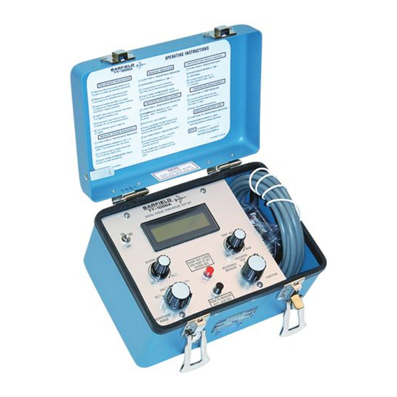
G. The SYSTEM RES. control knob (8), a ten-turn potentiometer used to adjust system lead resistance 2 to 25Ω, when test leads are shorted, and the red pushbutton is depressed. Figure 3 TT1000A Front Panel Layout 56-101-00901 Revision F Page 7... -
Page 15: General Operating Instructions
B. Preparation for Use 1. Battery Installation / Replacement a) Place the TT1000A on a clean area. (A clean cloth or paper pad placed next to the TT1000A to receive the panel is desirable.) Remove the four corner panel screws. Lift the panel high enough (approx. -
Page 16: Figure 4 Voltage Conversion
45V battery connector can be connected and connect. Then, slide panel assembly downward into place. 2. Perform the TT1000A Battery check prior to testing as follows: a) To check the 45-volt battery used for insulation testing, rotate the FUNCTION selector switch to RESISTANCE MEASURE position and the RESISTANCE RANGE selector to BAT. -
Page 17: System Lead Resistance Test Procedure
1. Do NOT press either pushbutton with test clips connected to the aircraft indicator. The current applied may damage the indicator. 2. Do NOT connect test clips to an energized circuit. Although the TT1000A is provided with protective devices, not all damaging potentials can be made completely safe. -
Page 18: Thermocouple Resistance Test Procedure
J. Disconnect the TT1000A and return the aircraft to its original configuration. 4. THERMOCOUPLE RESISTANCE TEST PROCEDURE A. Disconnect lead wires from the engine thermocouple terminals. B. Carefully connect test lead clips to each of the terminals insuring a good electrical connection. -
Page 19: Indicator Test Procedure (With Specified Lead Resistance)
F. Disconnect aircraft thermocouple leads from temperature indicator. G. Connect test lead clips to indicator terminals. Observe polarity. Alumel is negative (-) and connects to the TT1000A BLACK clip: Chromel is positive (+) and connects to the TT1000A RED clip. -
Page 20: Potentiometric Or Servo Type Indicator Test Procedure
1. Disconnect aircraft power to indicator (refer to the Aircraft Maintenance Manual). 2. Disconnect electrical connector at rear of indicator. 3. Connect TT1000A leads to probe pins sized to fit Chromel and Alumel pin sockets of aircraft plug removed from indicator. -
Page 21: Temperature Measurement Test Procedure
8. Rotate the TEMP. ADJ. control for desired test points as read on the TT1000A digital display. 9. Compare readings of indicator under test with TT1000A indications. Note: Indicator must agree with TT1000A reading to within manufacturer's specifications. 10. Place aircraft temperature indicating system power to OFF. -
Page 22: Chapter 3: Receiving, Shipping, & Storage
TT1000A. It is also recommended that the TT1000A and its carrying case be carefully inspected for damage. If damaged, immediately notify the carrier and the manufacturer.
Need help?
Do you have a question about the TT1000A and is the answer not in the manual?
Questions and answers