
Related Manuals for barfield 1811NG


Summary of Contents for barfield 1811NG
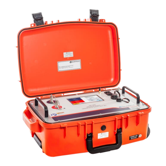
- Page 1 1811NG Pitot-Static Test Set USER INSTRUCTION MANUAL M/N 1811NG, P/N: 101-01178 Doc. P/N: 56-101-01178 Revision K September 2, 2020 _____________________________ Copyright © 2020 Barfield Inc. All Rights Reserved.
- Page 2 Barfield Inc. Confidential and Proprietary Information SAFETY This document and all the information contained herein is the sole property of Barfield Inc. No intellectual property rights are granted by the delivery of this document or the disclosure of its content.
- Page 3 SAFETY Before using this instrument, the operator should read and understand all of the related data. This includes the applicable local safety procedures, this publication and the instructions for the accessories/options/equipment you are using it with and the system or components under test. This equipment was designed to be safe when used as per the procedures of this Instruction Manual.
- Page 4 MARKING AND SYMBOLS This instrument meets the relevant European safety directives . The instrument carries the CE mark. Wi-Fi disabled for EMC SYMBOLS ON THE INSTRUMENT Warning – Read and understand operator’s manual before using this machine 56-101-01178 Revision K Page | iv...
- Page 5 You MUST have your name and address on file at Barfield as a registered user of this equipment to be able to obtain the service covered by the warranty.
- Page 6 In case of malfunction, contact the manufacturer to obtain the list of approved repair facilities worldwide, ensuring that this equipment will be serviced using proper procedures and certified instruments. BARFIELD PRODUCT SUPPORT DIVISION Telephone (305) 894-5400 Shipping Address: (800) 321-1039 Barfield, Inc.
-
Page 7: Revision Record
REVISION RECORD REV. ECO # REV. DATE DESCRIPTION OF CHANGE January 20, 2015 Initial Release. 260-01092 March 18, 2015 Logo Page iii, Table 2, Figure 10, Pages 37 & 42. CE Mark Page iii, Figure 1 Page 1, Table 3 Page 260-01107 July 1, 2015 4, 2.B. -
Page 8: Table Of Contents
TABLE OF CONTENTS Safety / Warning / Cautions Symbols Attention / Contact Information Maintenance Revision Record Table of Contents List of Figures List of Tables PAGE INTRODUCTION ........................... 1 1. PUBLICATION BREAKDOWN ..................1 2. INFORMATION PROVIDED WITH THE TEST SET ............1 3. - Page 9 APPENDIX F: CABIN PRESSURE MODE .................. 77 1. SECTION 1 ........................77 2. SECTION 2 ........................79 APPENDIX G: IBF SYSTEM MODE ................... 85 APPENDIX H: FIELD FIRMWARE UPDATE PROCEDURE VIA USB & BARFIELD ADTS APP ..............................90 56-101-01178 Revision K Page | ix...
-
Page 10: List Of Figures
FIGURE 7 POWER SUPPLY CABLE ..................13 FIGURE 8 DO NOT OBSTRUCT VENTS ................... 13 FIGURE 9 HUMID AIR EXHAUST ....................13 FIGURE 10 1811NG PRESSURE CONNECTIONS ..............14 FIGURE 11 1811NG FRONT PANEL ..................15 FIGURE 12 INSTRUCTION MANUAL, P/N 56-101-01178 ............17 FIGURE 13 ELECTRICAL CABLE, P/N AE9887-ND .............. - Page 11 FIGURE F.6 INITIALIZATION SCREEN ..................79 FIGURE F.7 CABIN PRESSURE MODE – STEP 1 ..............80 FIGURE F.8 DPS1000 & 1811NG CONNECTION PORTS ............80 FIGURE F.9 WARNING SCREEN ....................81 FIGURE F.10 CABIN PRESSURE MODE – STEP 2 ..............81 FIGURE F.11 CABIN PRESSURE MODE –...
- Page 12 LIST OF TABLES PAGE TABLE 1 PHYSICAL CHARACTERISTICS .................. 5 TABLE 2 ENVIRONMENTAL ....................... 5 TABLE 3 CONFORMITY ......................5 TABLE 4 AERONAUTICAL SPECIFICATIONS................6 TABLE 5 PRESSURE UNITS SPECIFICATIONS ................ 7 TABLE 6 DISPLAY UNITS ......................7 TABLE 7 ENGINE PRESSURE RATIO TEST TABLE ..............57 TABLE 8 AERONAUTICAL LIMITS PROFILE –...
-
Page 13: Introduction
INTRODUCTION 1. PUBLICATION BREAKDOWN This user instruction manual establishes the standards of operation for the 1811NG, Pitot- Static Test Set. Its purpose is to provide enough information for the personnel unfamiliar with this unit to understand it, identify its parts, and operate it in accordance with proper procedures, operating techniques, precautions and limitations. -
Page 14: Recertification
Contact Barfield for Maintenance and Calibration requirements. B. At the conclusion of the power up initialization the 1811NG will display the date when it was “Last Calibrated” in the format of Day–Month-Year and will provide the user with the number of days remaining before its calibration due date with a statement of “Cal due”... -
Page 15: Mobile Device's App Information
4. MOBILE DEVICE’S APP INFORMATION Visit the Apple App Store or Google Play App Store to download the free application, “Barfield ADTS”, onto your iOS or Android device (not supplied). You can also check Barfield’s website to be redirected to the app store at: https://www.barfieldinc.com/en/services-and-offers/ground-support-test-equipment... -
Page 16: Figure 3 Limited 2 Year Warranty
BARFIELD or an authorized distributor that this product will be free from defects in material and workmanship under normal use and service for two years after date of purchase. BARFIELD reserves the right, before having any obligation under this limited warranty, to inspect the damaged BARFIELD product, and all costs of shipping the DPS1000/1811NG product to BARFIELD for inspection shall be borne solely by the Purchaser. -
Page 17: Chapter 1: General
B. The 1811NG Digital Pitot Static Test Set meets the requirements as described in Federal Aviation Regulation Part 43, Appendix-E, which defines the requirements for accuracy of an aircraft’s altimeter and as such is reference for the accuracy of Pitot-Static testers. -
Page 18: Table 4 Aeronautical Specifications
D. Performance WARNING: The 1811NG is NOT suitable for RVSM Accuracy requirements. Aeronautical Ps Channel Rate of Pt Channel Rate of Mach Climb Altitude Calibrated Airspeed RtCAS Units Feet ft/min knots (kts) kts/min Operating 0 to 20,000 50 to 600... -
Page 19: Table 5 Pressure Units Specifications
Pressure Units Qc Channel RtQc Rate of Rate of Channel (Note: Pt = Qc + Ps) Change Units inHg (abs) inHg/min inHg (diff) inHg/min Ratio: Pt7 / (*3) Operating 2.693 to 0.1 to 16 0.0 to 40 0.5 to 10 0.1 to 10 Range 38.0... -
Page 20: Instructions For Use
3. INSTRUCTIONS FOR USE A. With the Barfield 1811NG Pitot and Static ports connected via the hoses (included) and mating aircraft adapters (not included) to their respective ports on the aircraft, the user is able to enter pressures or equivalent aeronautical values using the Test Set’s touch screen input display to drive the aircraft system to the required points of test. -
Page 21: Technical Assistance
4. TECHNICAL ASSISTANCE A. For technical assistance on the Barfield 1811NG, please contact Barfield Inc. at: TECHNICAL CUSTOMER SUPPORT - GSTE BARFIELD, INC. P.O. BOX 025367 MIAMI, FL 33102-5367 Telephone (305) 894-5400 (800) 321-1039 (305) 894-5401 Email gsesales@barfieldinc.com 56-101-01178 Revision K... -
Page 22: Chapter 2: Ratings
1. SUPPLY VOLTAGES A. The Barfield 1811NG Pitot Static Test Set may be powered from either 100 to 120 VAC @ 50 or 60 Hz, 400 VA, or from 200 to 240 VAC @ 50 or 60 Hz, 400 VA. -
Page 23: Chapter 3: Installation
The user should take inventory of the package contents to insure the following items are there: 1. 1811NG Pitot Static Test Set, P/N 101-01178. 2. Hose kit P/N 115-00633 composed of: a) 1 each Blue 25 ft Hose with AN4 fittings and 1 tethered plug for STATIC (Ps) port connection, P/N 115-00630. -
Page 24: Grounding (Earthing)
B. The 1811NG chassis may be grounded to the aircraft or instrument under test using the Ground stud located in the upper right corner of the panel as depicted item 5 in Figure 11. -
Page 25: Electrical Connections
4. VENTILATION / DRAINAGE A. Ventilation The 1811NG has exhaust vents on the right side of the unit which must not be blocked. Also, there are intake vents on the left side for drawing air though the case which also must be kept free from obstructions. -
Page 26: Pneumatic Pressure Connections
A. Pitot and Static Ports 1. Pt (pitot) - AN4 (MS33656-4) 2. Ps (static) - AN4 (MS33656-4) Figure 10 1811NG Pressure Connections B. Blanking Caps When not in use the panel mounted Blanking Caps should be fitted to the ports to prevent the introduction of any foreign matter. -
Page 27: Chapter 4: Operation
CHAPTER 4: OPERATION 1. OPERATING CONTROLS A. Front Panel Switches and Controls (Components shown in Figure 11). Figure 11 1811NG Front Panel Key to Figure 11: Pitot (Pt) pressure port Connect to Aircraft Pitot system. This is also referred to as the Pt port and Total Pressure port. -
Page 28: Positioning
Micro USB port OEM use only. Note (*1): When a remote iOS or Android device is connected to 1811NG, the touch screen on the1811NG is disabled except for the “Disconnect Remote” and “Local UI: enable” buttons (refer to APPENDIX E: WI-FI CONNECTION PROCEDURE). -
Page 29: Figure 12 Instruction Manual, P/N 56-101-01178
Figure 12 Instruction Manual, P/N 56-101-01178 Figure 13 Electrical Cable, P/N AE9887-ND Figure 14 Hose Kit, P/N 115-00633 56-101-01178 Revision K Page | 17... -
Page 30: Figure 15 Antenna, P/N 126-00001
Figure 17 AN4 Caps with Lanyard, P/N 176-00001 B. Items not included 1. Ruggedized shipping case Barfield P/N 194-00073 see drawing in Figure 6. 2. Nav-Aids Pitot Static Adapters – Contact Barfield with your aircraft requirements. 3. Wi-Fi enabled tablet - either Android or IOS device. -
Page 31: Preparation
Pitot and Static hoses. Each Test Set is completely calibrated and tested before shipment. However, to ensure the integrity of the tests, the 1811NG should be leak checked before each use. To help automate this process, use the predefined ATP Test Set–only. -
Page 32: Operating Modes
6. OPERATING MODES A. The 1811NG has two pneumatic control modes of operation, (1) the default mode: 2- channel (Ps & Pt) mode and (2) 1-channel: Pt-Only mode which the user can select by following this Menu sequence: Main Menu, Page 2, Additional Functions, Control Mode. -
Page 33: Test Set Configuration Status Display
D. Below are examples of the 2-modes: 1. Default: Aeronautical 2-Channel (Ps&Pt) (see Figure 19). 2. Aeronautical 1-Channel (Pt Only) (see Figure 20). Figure 19 Default 2-Channel (Dual Ps, Pt) mode Figure 20 Optional 1-Channel (Pt Only) Mode Note: Please refer to Appendix D for the complete Menu Navigation. 7. -
Page 34: Figure 21 Test Set Configuration Information Displayed
C. Altitude Correction: Indicates the correction factor entered by the user. Default = 0 unless user specifies otherwise D. Auto Leak Recovery: Enabled or Disabled Note: The Configuration Status area is an active touch zone the user can navigate by either pressing the top right box or selecting this Menu sequence: Main Menu, Page 2, Setup 1. -
Page 35: User Interface Menu And Display
8. USER INTERFACE MENU AND DISPLAY A. The UI “User Interface” was designed and structured to provide the user/operator with an efficient and intuitive man-machine interface. 1. The left-half of the screen provides all the measurement and control display screens. 2. -
Page 36: Figure 23 Hold/Resume Feature Displayed
touch zone area, which will cause the Target keypad to be displayed for user entry. For this example, the ALT touch zone was selected. 9. While in Control mode, the user can select the Hold feature which sets the controller Target values to present ALT and CAS values at the time Hold is selected. -
Page 37: Figure 25 Display Setup: 4-Parameter
B. Display Setup – Configuring display format The Display Setup allows the user to configure the display as a 2 or 4-parameter format. While operating in Aeronautical mode for example, the 4-parameter format will allow ALT, ROC, CAS and MACH or ALT, ROC, CAS, and RtCAS to be displayed. While in Control mode, Target values can be assigned to ALL 4 parameters by simply touching the screen on each of the 2 or 4-parameter displayed areas. -
Page 38: Figure 27 Display Units - For Aeronautical Mode
Figure 28 Display Units – for Pressure Units Mode D. Leak Testing - There are two types of leak tests supported on the 1811NG: the traditional leak testing using the Leak Rate Timer or the Automatic Test Process (ATP) Leak Test Profiles. -
Page 39: Figure 30 Leak Rate Timer Results
1. Leak Rate Timer – traditional leak testing which the user sets the target values of the desired ALT and CAS values. Once the Test Set achieves those target values the user selects Leak Measure mode followed by Leak Testing followed by Leak Rate Timer being selected. -
Page 40: Figure 31 Select Atp Leak Test Profile
Figure 31 Select ATP Leak Test Profile The ATP Leak Test provides the following profile options (see Figure 32): a) ALR “Auto Leak Recover” can be “(X)” selected/deselected b) Ambient Comp can be “(X)” select/deselected Ambient Comp compensates for local ambient barometric pressure to ensure for example that a 5,000 ft. -
Page 41: Figure 32 Atp Leak Test - Parameter Profile Screen
Figure 32 ATP Leak Test - Parameter Profile Screen Figure 33 ATP Leak Test Results Screen E. Go To Ground: This function will take the Test Set back to Ground (ambient barometric pressure altitude) and CAS = 0 Kts. Go To Ground can be selected while operating in Leak Measure or Control mode. -
Page 42: Figure 34 Go To Ground Confirm Screen
Main Menu: Go To Ground Figure 34 Go to Ground Confirm Screen The user can select “Go To Ground” from the Main menu, while in either Leak Measure or Control mode. At the conclusion of Go To Ground, the Test Set will perform an AutoZero function to trim off any small Qc pressure offset that may have crept into the Qc transducer typically due to thermal component (Test Set Warming or cooling). -
Page 43: Figure 36 Setup 1
Below is an example of the Aircraft static port being located 20 ft. physical higher ( + ) than where the 1811NG Test Set is located (see Figure 38). Note: If the 1811NG Test Set was physically higher than the instrument or aircraft then the altitude correction would be entered as a negative ( - ) value. -
Page 44: Figure 37 Altitude Correction Screen
Figure 37 Altitude Correction Screen Figure 38 Altitude Correction On-Aircraft Figure 39 Altitude Correction Keypad 56-101-01178 Revision K Page | 32... -
Page 45: Figure 40 Test Set Configuration, Updated Altitude Correction
(static) port vented to ambient (local barometric pressure). When the single channel Pt- only mode is selected, the 1811NG will perform a Go To Ground function before transitioning into this mode to ensure the Test Set Ps port is at ambient barometric pressure, at the conclusion of the Go To Ground the Test Set will leave the Ps port vented to ambient while driving the Pt port to the Target pressure specified by the user. -
Page 46: Figure 43 Setup 2 - Selecting Limit File To Edit
G. Setup 2 – (PIN Required) The Setup 2 menu is PIN protected to provide some level of security to the activities that can be accomplished under this menu structure. After entering the user PIN code (default code is 123456), the following screen (see Figure 42) will allow: Figure 42 Setup 2 - Selecting Limit File to Edit 1. -
Page 47: Figure 44 Delete Custom Limits
Step 1 Touch to open. Figure 44 Delete Custom Limits (Continued on next page…) Step 2 Touch to open. Step 3 Ensure “Limits” is different from “custom limits” created. Step 5 Touch “delete” to erase the “custom limits” created Figure 44 Delete Custom Limits System Config a) Set Date &... - Page 48 b) Wi-Fi Option: enables or disables the Wi-Fi capability. c) Cabin Pressure Mode: refer to Appendix F: Cabin Pressure Mode. 3. Wi-Fi Option: refer to Appendix E: Wi-Fi Connection Procedure. a) Flash - HUIM from USB: Update HUIM firmware from dpsx file located on the USB flash drive.
-
Page 49: Figure 45 Backlight Adjustment
Note: If touch screen sensitivity or zone accuracy has shifted, allow user to calibrate touch screen. K. Log File - There are two log file selections available Main Menu: Page 2, Page 3 1. Current History – Recorded event history since the unit was last powered on 2. -
Page 50: Test Set Operation
9. TEST SET OPERATION A. Preliminary Setup 1. Ensure that the 1811NG Power ON//OFF switch (8) is in the OFF position prior to connecting the AC power cable. 2. As a standard practice and under normal circumstances it is recommended that the 1811NG not have hoses connected prior to initialization. -
Page 51: Figure 47 Initialization Display
The 1811NG has two modes of operation, Leak Measure and Control. The default mode of operation for the 1811NG is Leak Measure mode. At the conclusion of power ON initialization the Test Set will be placed in the Leak Measure mode. - Page 52 D. Control Mode The Control mode on the 1811NG provides a two-channel pneumatic controller. The 1811NG controller is referred to as the PCM (Pneumatic Control Module). This module provides an absolute pressure controller for the STATIC (Ps) channel and a differential pressure controller for the PITOT (Pt) channel.
-
Page 53: Test Set Leak Test
CAS and ALT and uses the Leak Rate Timer to measure the Leak Rate. b) Method-(2) ATP Leak Test: the 1811NG has an automated feature called ATP Leak Test which allows the user to setup a profile ahead of time with the following parameters: (see Figure 49 and Figure 50). -
Page 54: Figure 49 Selecting Atp Leak Test Profile
Figure 49 Selecting ATP Leak Test Profile Figure 50 Leak Test Profile - Parameters Screen 5. From the UI main menu, touch to select “Leak Testing”. A panel appears with two options: “Leak Rate Timer and ATP Leak Test Profiles. a) Touch “ATP Leak Test Profiles”. -
Page 55: Figure 51 Leak Test Timer Screen
B. STATIC and PITOT Test Set Leak Test – (Test Set and hoses only) • Confirm hoses connected to both Ps and Pt ports on the 1811NG. • Confirm the other end of each hose is sealed with an AN4 plug. -
Page 56: Figure 52 Leak Rate Timer, Unit Safe At Ground
main menu. Select Go To Ground. Touch “Yes” to confirm Go To Ground. k) Wait for Test Set to reach Ground (ambient pressure altitude). Test Set displays “Unit Safe at Ground”. The Test Set will automatically switch into Leak Measure mode with the PITOT (Pt) and STATIC (Ps) ports Vented to ambient and the pumps will be powered off. -
Page 57: Figure 54 Atp Leak Test Results
If Ps Low ALT was selected it will be tested second. If Ps High ALT was selected, it will be tested third. • At the conclusion of the ATP Leak Test, the 1811NG will automatically perform a Go To Ground function and the following screen will display the results (see Figure 54). -
Page 58: Aircraft Testing
Make sure that other ports in the system being tested are sealed before continuing. 3. It is recommended to have the 1811NG chassis grounded to the aircraft or UUT using the Ground stud located in the upper-right corner of the panel as depicted in item 5 of Figure 4. -
Page 59: Figure 57 Unit Safe At Ground
Note: The 1811NG is capable of conducting a combined Pitot and Static test (as described above) or individual system leak tests. To accomplish a single channel (Pitot only or Static only) modify the procedures by simply not entering Target value for the parameter / channel. - Page 60 1. For detail explanation of the ATP Leak Test capability and parameter field descriptions, reference section B-3.30 “Using Method-(2) ATP Leak Test”. 2. Verify the 1811NG including hoses and the Aircraft Pitot System Leak Test and Static System Leak Tests have been completed.
-
Page 61: Figure 56 Leak Test Results
7. Using the AMM or CMM, select the appropriate Leak Test ATP Leak Test Profile a) From Main Menu, select Leak Testing. The Leak Testing panel opens. b) Touch ATP Leak Test Profiles. The ATP Leak Profiles panel is displayed. c) Select the appropriate profile to perform the Leak Test as specified by the AMM or CMM. - Page 62 Test Set operation while the AMM or CMM dictates the specific test process, sequences and values. 1. Ensure the 1811NG is powered ON. Wait for Initialization to be completed, the system to be safe at Ground and the display to indicate “Vented”.
- Page 63 Note: If required, select Go To Ground and wait for the Test Set to indicate “Unit Safe at Ground”. 2. Connect the Pitot (Pt) port of the 1811NG to the aircraft or ASI instrument being tested. Note: The Static (Ps) hose is not required to perform a Pitot system test if the Test Set is configured for “1-Channel Pt Only”...
- Page 64 3. If performing a Pitot only test, configure the 1811NG to “1-Channel Pt only” mode as follows: Note: Test Set should be “Vented” to ambient and in Leak Measure mode at this time. a) From the Main Menu screen, select the blue button “page2”.
- Page 65 Test Set operation while the AMM or CMM dictates the specific test process, sequences and values. 1. Verify the 1811NG is powered ON. Ensure Initialization has completed, the system is safe at Ground and the display indicates “Vented”.
- Page 66 17. This Completes the “Combine Testing of the Aircraft Pitot and Static System”. G. MACH Test and Constant MACH The 1811NG can provide either constant CAS “calibrated airspeed” or constant MACH. The parameter which is held constant is determined by which Target parameter the user enters...
- Page 67 PITOT (Pt) channel. Similarly, if the user enters a MACH Target value then MACH is the controlling parameter. With a Target value entered for MACH “i.e. Constant MACH”, once the 1811NG reaches the Target MACH value, the PITOT (Pt) channel controller will continue to maintain the MACH value requested while the STATIC (Ps) Target value is changed by the user entering a different ALT Target.
-
Page 68: Engine Pressure Ratio (Epr) Test
10. Record the trip point where the switch contacts open. 11. On completion of the Airspeed switch testing select the Go To Ground function and wait for the “Unit Safe at Ground” message to be displayed. Note: The above method Nudge feature can be used with any of the Controlled Target parameters such as ALT, ROC, MACH, RtCAS, Ps, Pt, EPR. -
Page 69: Table 7 Engine Pressure Ratio Test Table
2. Method 2: EPR Testing using EPR Mode. The 1811NG has an actual EPR Mode that can be used to test the EPR transmitter. EPR = Pt/ Ps (where Ps= Inlet pressure and Pt=Outlet pressure). In EPR Mode the 1811NG provides display of the individual pressures for PT2 and PT7 as well as the exact EPR Ratio resulting from the equation of PT7 / PT2. -
Page 70: Shutdown Procedure
Enter the first Pt (PT7) pressure Target value or the first EPR Target. e) After the 1811NG achieves both the Target values confirm the EPR Ratio reading. f) Repeat the process by entering both Target values for all increments of test. - Page 71 CAUTION: Do not remove STATIC (Ps) or PITOT (Pt) hose or Nav-Aids adapters before Test Set displays “Unit Safe at Ground”. 3. Switch Power OFF. 4. Disconnect the STATIC and PITOT hoses from the aircraft ports and or adapters. 5. Disconnect the STATIC and PITOT hoses from the tester ports. 56-101-01178 Revision K Page | 59...
-
Page 72: Chapter 5: Receiving, Shipping, And Storage
CHAPTER 5: RECEIVING, SHIPPING, AND STORAGE 1. RECEIVING No special unpacking procedures are necessary. It is recommended that the factory-shipping container and packing materials be retained should it become necessary to re-ship the Test Set for a variety of reasons, including O.E.M. recertification. It is also recommended that the Test Set undergo a leak check upon receipt and its carrying case should be carefully inspected for damage. -
Page 73: Chapter 6: Maintenance
B. Inspect the ports, hoses and aircraft adapters for the presence of moisture or any type of foreign matter. C. With the 1811NG disconnected from the hose and adapter assemblies, power the unit on and observe the initialization routine to make sure there are no apparent issues reported. -
Page 74: Appendix A: Abbreviations & Glossary
APPENDIX A: ABBREVIATIONS & GLOSSARY Absolute Aircraft Maintenance Manual Altitude (ft or m). Auto Leak Recover Application Airspeed Indicator Automatic Test Process Calibrated AirSpeed (kts or km/h) Component Maintenance Manual Engine Pressure Ratio Degrees Fahrenheit Degrees Celsius Fig. Figure Foot Gauge Hour Hecto meter... - Page 75 Personal Identification Number Static Pressure Pounds per square inch Pitot Pressure PsRt Ps Rate, rate of Ps pressure change PtRt Pt rate, rate of Pt pressure change Differential pressure (Qc = Pt - Ps) Local atmospheric pressure Barometric pressure at sea level Rate Of Climb in units of (ft/min or m/min) Rate RtCAS...
-
Page 76: Appendix B: Operating Limits
APPENDIX B: OPERATING LIMITS The 1811NG comes with 2 pre-defined sets of operating limits: the default limits profile and max limits profile. The unit has limits files for each of the 3-modes of operation, Aeronautical, Pressure units and EPR. There will be a default limits profile for each of the 3-modes; these values are stored in an R/O “read only”... -
Page 77: Table 10 Pressure Limits Profile - (Default)
Operating Limits (con’t) Pressure Limits Profile – (default) Parameters Limits Comments Ps Min 2.693 inHg Ps Minimum Pressure Ps Max 32.000 inHg Ps Maximum Pressure Qc Min 0.000 inHg Qc Minimum Pressure Qc Max 30.000 inHg Qc Maximum Pressure Pt Min 2.693 inHg Pt Minimum Pressure Pt Max... -
Page 78: Table 13 Epr Limits Profile - (Max)
Operating Limits (con’t) EPR Limits Profile – (max) Parameters Limits Comments Ps Min 2.693 inHg Ps Minimum Pressure Ps Max 38.000 inHg Ps Maximum Pressure Pt Min 2.693 inHg Pt Minimum Pressure Pt Max 78.000 inHg Pt Maximum Pressure EPR Min 0.10 Ps Minimum Rate EPR Max... -
Page 79: Appendix C: 1811Ng Internal Pneumatic Diagram
APPENDIX C: 1811NG INTERNAL PNEUMATIC DIAGRAM 56-101-01178 Revision K Page | 67... -
Page 80: Appendix D: Menu Navigation
APPENDIX D: MENU NAVIGATION 56-101-01178 Revision K Page | 68... -
Page 81: Appendix E: Wi-Fi Connection Procedure
APPENDIX E: WI-FI CONNECTION PROCEDURE The DPS1000 and 1811NG Test Sets can be controlled using a Wi-Fi enabled Android or iOS tablet or cellphone (not supplied) as a wireless remote-control device. Download the free Barfield app from the Google Play Store or Apple App Store - search for “Barfield ADTS”. -
Page 82: Figure E.3 Password Request
Figure E.4 “Connect” screen with unit selected displayed 7. Press “Connect”. 8. You are now ready to use the “Barfield ADTS” app with your Test Set. 9. Properly disconnect the Android device from the Test Set using one of the following... -
Page 83: Figure E.5 Disconnect From Adts App Menu
Select “Disconnect Remote” from the Test Set’s touch screen (refer to Figure E.6). Figure E.6 “Disconnect Remote” button Note: By default, while the Test Set is connected to the Android device, the 1811NG’s touch screen is disabled. Only the “Disconnect Remote” and “Local UI: enable”... -
Page 84: Figure E.7 "Local Ui: Enable" Button
Remote UI disabled” (refer to Figure E.8). Figure E.8 Remote Connected/Remote UI disabled B. Establishing Wi-Fi Connection with Apple Device 1. “Launch the “Barfield ADTS” app. 2. Press “Connect” (refer to Figure E.9). Figure E.9 Connect Screen 56-101-01178 Revision K... -
Page 85: Figure E.10 "Information" Wi-Fi Connect Screen
3. If you are not connected to a DPS1000/1811NG Test Set Wi-Fi, the “Information” screen will appear (refer to Figure E.10). Figure E.10 “Information” Wi-Fi Connect Screen 4. Go to your device’s Wi-Fi connection “Settings” screen. 5. Connect to available DPS1000/1811NG Wi-Fi (refer to Figure E.11) Note: If connecting to the unit for the first time, a password request will trigger (refer to Figure E.9). -
Page 86: Figure E.12 Password Request
Figure E.13 “Connect” screen with unit selected displayed 7. Press “Connect”. 8. You are now ready to use the “Barfield ADTS” App with your Test set. 9. Properly disconnect the Apple device from the Test Set using one of the following... -
Page 87: Figure E.14 Disconnect From Adts App Menu
Select “Disconnect Remote” from the Test Set’s touch screen (refer to Figure E.15). Figure E.15 “Disconnect Remote” button Note: By default, while the Test Set is connected to the Apple device, the 1811NG’s touch screen is disabled. Only the “Disconnect Remote” and “Local UI: enable”... -
Page 88: Figure E.16 "Local Ui: Enable" Button
Figure E.16 “Local UI: enable” button Note: A yellow button on the remote’s screen will indicate “Remote Connected, Remote UI disabled” (refer to Figure E.17). Figure E.17 Remote Connected/Remote UI disabled 56-101-01178 Revision K Page | 76... -
Page 89: Appendix F: Cabin Pressure Mode
It should be noted that this test is not commonly performed on aircraft. Therefore, the Cabin Pressure testing feature is disabled in the default configuration of the Test Set (as shipped from Barfield). Section 1 below describes the process of enabling the Cabin Pressure function while Section 2 describes the actual usage of the Cabin Pressure Mode. -
Page 90: Figure F.3 Setup 2 Screen
3. On the numbered keypad, enter the user PIN code (default code is “123456”). Touch “Enter”, “Setup 2” screen is displayed (see Figure F.3). Figure F.3 Setup 2 Screen 4. Touch “System Config”. A screen appears with three options. Touch “Cabin Pressure Mode Disabled”... -
Page 91: Section 2
5. The unit will change the Cabin Pressure Mode to Enabled (see Figure F.5). Figure F.5 Enabled Cabin Pressure Mode 6. The unit is now ready to be used in the Cabin Pressure Mode. In order to access the mode, please re-start the unit. 2. -
Page 92: Figure F.7 Cabin Pressure Mode - Step 1
Note: In Step 1, ensure that the cabin of the aircraft is open and the pitot port of the unit is vented to ambient (Ps port connection no required). Please refer to Figure F.8 for examples of Pitot port venting to ambient. DPS1000 Connection 1811NG Connection Figure F.8 DPS1000 & 1811NG Connection Ports 56-101-01178 Revision K Page | 80... -
Page 93: Figure F.9 Warning Screen
4. Follow on-screen instruction. Touch “Ambient Measure”. A warning pop-up window is displayed with the message below (see Figure F.9). Figure F.9 Warning Screen 5. Touch “Yes”. Continue to follow on-screen instructions. Step 2 window is displayed (see Figure F.10). Here, the unit will vent to ambient. Figure F.10 Cabin Pressure Mode –... -
Page 94: Figure F.11 Cabin Pressure Mode - Step 3
6. Once unit is vented, Step 3 screen will appear (see Figure F.11). The Cabin Measure button will be available. Please ensure that the cabin is sealed and ready for pressurization as per AMM. Figure F.11 Cabin Pressure Mode – Step 3 7. -
Page 95: Figure F.13 Cabin Pressure Mode - Measuring Cabin Pressure And Rate
8. Figure F.13 Cabin Pressure Mode – Measuring Cabin Pressure and Rate shows the screen for the cabin pressure mode on which the unit is monitoring the change in the cabin pressure and displays this value in unit of psi and ROC in ft/min. Figure F.13 Cabin Pressure Mode –... -
Page 96: Figure F.15 Cabin Pressure Mode - Venting Process
Figure F.15 Cabin Pressure Mode – Venting Process 12. Once the venting process is completed, the unit is safe to power off (see Figure F.16). Figure F.16 Cabin Pressure Mode – Step 2 56-101-01178 Revision K Page | 84... -
Page 97: Appendix G: Ibf System Mode
APPENDIX G: IBF SYSTEM MODE The following appendix details the configuration and usage of the unit when setup to perform in IBF (Inlet Barrier Filter) Mode. The purpose of the IBF is to protect the turbine engine from foreign damage and micro erosion when operating in normal and severe environmental conditions. -
Page 98: Figure G.3 Additional Functions Screen
6. Select “Additional Functions”. A new screen appears (see Figure G.3). Figure G.3 Additional Functions Screen 7. Touch “IBF Inlet Barrier Filter Mode”. Step 1 screen is displayed with the message below (see Figure G.4). Figure G.4 IBF Step 1 Screen 56-101-01178 Revision K Page | 86... -
Page 99: Figure G.5 Warning Screen
8. Touch “IBF Vent/Tare”. A warning screen appears with the prompt in below. Figure G.5 Warning Screen 9. Select “Yes” to confirm this action. Step 2 screen is briefly displayed while unit is venting to ambient and performing Tear function (see Figure G.6). Figure G.6 IBF Step 2 Screen Note: Unit is now vented to Ambient with ALT Tare at 0ft pressure altitude and dP Tare at 0.0inH... -
Page 100: Figure G.7 Ibf Control Mode Screen
10. Step 3 screen is displayed and “IBF Control” button is enabled (see Figure G.7). Figure G.7 IBF Control Mode Screen 11. Select “IBF – Control”. The unit will transition into control mode with the Target value (both ALT & dP) set to the current pressure measure on the Static (Ps) port. 12. -
Page 101: Figure G.9 Vent To Ambient Screen
15. Once testing is completed, touch “Exit”. A warning screen appears with the prompt below (). Figure G.9 Vent to Ambient Screen 16. Select “Yes”. The unit will briefly vent and a new screen is displayed with the message below (see Figure G.10). Figure G.10 Unit Safe at Ground 17. -
Page 102: Appendix H: Field Firmware Update Procedure Via Usb & Barfield Adts App
APPENDIX H: FIELD FIRMWARE UPDATE PROCEDURE VIA USB & BARFIELD ADTS APP (Please refer to the 42-101-01175_01178 for this procedure) 56-101-01178 Revision K Page | 90...
Need help?
Do you have a question about the 1811NG and is the answer not in the manual?
Questions and answers