
Related Manuals for barfield 2311FA


Summary of Contents for barfield 2311FA
- Page 1 2311FA Pressure Tester USER INSTRUCTION MANUAL M/N: 2311FA, P/N: 101-00212 Doc. P/N: 56-101-00212 Revision E August 8, 2023 ____________________________________ Copyright © 2023 Barfield Inc. All Rights Reserved.
- Page 2 Barfield Inc. Confidential and Proprietary Information. This document and all the information contained herein is the sole property of Barfield Inc. No intellectual property rights are granted by the delivery of this document or the disclosure of its content.
- Page 3 SAFETY Before using this instrument, the operator should read and understand all of the related data. This includes the applicable local safety procedures, this publication, and the instructions for the accessories/options/equipment you are using it with and the system or components under test. This equipment was designed to be safe when used as per the procedures of this Instruction Manual.
- Page 4 CAUTIONS CAUTION: To prevent damage to the instrument, do not let dirt get into the pressure mechanism. Before you attach equipment, make sure it is clean. CAUTION: Do not allow Master Gauge to go below zero. CAUTION: Do not apply vacuum or a hydraulic vacuum to Master Gauge. CAUTION: Do not insert objects into the Master Gauge.
- Page 5 In case of malfunction, contact the manufacturer to obtain the list of approved repair facilities worldwide, ensuring that this equipment will be serviced using proper procedures and certified instruments. BARFIELD PRODUCT SUPPORT DIVISION Telephone (305) 894-5400 Shipping Address: (800) 321-1039 Barfield, Inc.
- Page 6 REVISION RECORD REV. ECO # REV. DATE DESCRIPTION OF CHANGE April 1, 1999 Initial release. Chapters 2 and 3 were reorganized. Updated Figure 1, 4 and 5, Table of 260-00717 January 25, 2008 Gauges, and Maintenance Information. Updated Manual Format. 260-00829 April 12, 2011 Updated warranty information.
-
Page 7: Table Of Contents
TABLE OF CONTENTS Safety / General Warnings / Pressure Warnings Cautions / Marking & Symbols Contact Information / Maintenance Information Revision Record Table of Contents List of Figures / List of Tables PAGE INTRODUCTION ......................1 1. PUBLICATION BREAKDOWN ..................1 2. - Page 8 Figure 2 Owner Warranty Registration Card ................2 Figure 3 Limited Warranty ......................3 Figure 4 2311FA Pressure Tester with a Digital Gauge (Not Included) ........4 Figure 5 Container/Shipping Case, P/N 194-00079 ..............8 Figure 6 2311FA Pressure Tester Parts ................... 9 Figure 7 2311FA Piston, Shaft, &...
-
Page 9: Introduction
INTRODUCTION 1. PUBLICATION BREAKDOWN This user instruction manual establishes the standards of operation for the 2311FA Pressure Tester. Its purpose is to provide sufficient information for the personnel unfamiliar with this tester to understand it, identify its parts, and operate it in accordance with proper procedures, operating techniques, precautions, and limitations. -
Page 10: Recertification
B. The Owner's Warranty Registration card (refer to Figure 2), is to be completed by the owner and returned to Barfield, Inc. within ten (10) days of purchase to ensure automatic update of printed matter and validation of warranty. To register your unit, please visit https://www.barfieldinc.com/warranty_registration... -
Page 11: Figure 3 Limited Warranty
Figure 3 Limited Warranty 56-101-00212 Revision E Page | 3... -
Page 12: Chapter 1: General
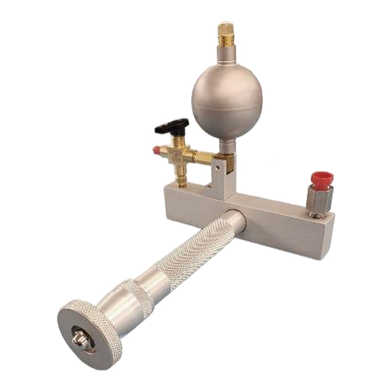
0-600 psi range. The Tester is proof tested to 1200 psi. 2. DESCRIPTION A. As depicted in Figure 4, the 2311FA consists of a cylinder equipped with a manually operated Piston for obtaining the desired outlet pressure. A fluid reservoir (located on top of the cylinder) is connected through a control valve to the inside of the cylinder. -
Page 13: Specifications
3. SPECIFICATIONS Note: The dimensions listed below exclude the Master Pressure Gauge connected at the Adapter (refer to Figure 6, item #14). The range, accuracy, and type for the Master Pressure Gauge (sold separately) depends on the requirements of the system(s) to be tested and the user's preferences (refer to Table 4). -
Page 14: Recommended Gauges
Three types of gauges are recommended and available depending on the requirements of the user: 1. Standard 2. Inspector Test 3. Digital Type Accuracy Pressure Range Barfield P/N 0-60 psig 304-00003 Standard (Analog) ±2% Full Scale 0-200 psig 304-00004 0-600 psig... -
Page 15: Consummables
6. CONSUMMABLES A. Vaseline FED SPEC VV-P-236A B. Teflon Tape MIL-T-27730A (obsolete), A-A-58092 C. Silicon Grease Parker Super-O-Lube, Dow Corning Molykote® 55 56-101-00212 Revision E Page | 7... -
Page 16: Chapter 2: Installation
1. 2311FA Pressure Tester, P/N 101-00212 2. Instruction Manual P/N 56-101-00212 B. Enclosure 1. A case, Barfield P/N 194-00079, facilitates protecting and carrying of the Tester. Case features include (refer to Figure 5): a) An injected molded case. Airtight, watertight, and dustproof case. -
Page 17: Chapter 3: Operation
CHAPTER 3: OPERATION 1. OPERATING CONTROLS A. The 2311FA parts are depicted in Figure 6. Top View Front View Rear View Figure 6 2311FA Pressure Tester Parts 56-101-00212 Revision E Page | 9... -
Page 18: Filling Tester With Fluid
CONTAMINATION OF THE WORK SURFACE. Note: Refer to Figure 6 to identify item numbers. A. Pressure Tester 2311FA is supplied empty, allowing users to fill it with the appropriate liquid according to its intended use (refer to section 1.5 RECOMMENDED FLUIDS). -
Page 19: Changing Tester Fluid
4. With the Selector Valve (#9) arrow pointing toward the Reservoir (#3), rotate the Screw Handle (#1) fully clockwise (CW). 5. Remove the Vented Plug (#16) from the Reservoir (#3). Fill the Reservoir completely with the appropriate fluid. Note: Once filled, the Tester must be maintained in a position approximately level with the Reservoir (#3) up. -
Page 20: Operation Procedures
4. Unscrew the Nut (#15) on the end of the cylinder and remove the Piston, Shaft, and Handle Assembly (#1) from the Tester. 5. Drain all the liquid from the Piston, Shaft, and Handle Assembly (#1) and from the Manifold and Sleeve Assembly (#2), in the plastic container. 6. - Page 21 3. Remove the Vented Plug (#16) from the Reservoir (#3). Note: Place a rag over the Vented Plug (#16) while removing it to avoid possible exhaust spray. 4. Fill the Reservoir (#3) completely with the same type of fluid that was used during the previous steps.
-
Page 22: Chapter 4: Receiving, Shipping, And Storage
CHAPTER 4: RECEIVING, SHIPPING, AND STORAGE 1. RECEIVING No special unpacking procedures are necessary. It is recommended that the factory- shipping container and packing materials be retained should it become necessary, for any reason, to re-ship the Tester, such as for the O.E.M. recertification. It is also recommended that upon receipt the test set should be carefully inspected for damage. -
Page 23: Chapter 5: Maintenance & Repair
CHAPTER 5: MAINTENANCE & REPAIR 1. GENERAL A. Refer to section 3.3 CHANGING TESTER FLUID for detailed instructions on the disassembly, cleaning, and reassembly of the tester to maintain the tester in serviceable condition. 2. REPAIR A. If during normal operation of the tester an excessive leak (more than 5% of full scale in one minute) is observed, then proceed as follows: Note: Except as noted, refer to Figure 6. -
Page 24: Figure 7 2311Fa Piston, Shaft, & Handle Assembly
Figure 7 2311FA Piston, Shaft, & Handle Assembly 11. Unscrew the large nut (#15) at the end of the cylinder and carefully withdraw from the Sleeve (#2). 12. Carefully remove the O-Rings from the Piston, Shaft, and Handle Assembly (#1) to avoid scratching the Piston.
Need help?
Do you have a question about the 2311FA and is the answer not in the manual?
Questions and answers