Table of Contents
Advertisement
To buy, sell, rent or trade-in this product please click on the link below:
http://www.avionteq.com/Barfield-1811HAAOA-Pitot-Static-Test-Set.aspx
1811HA (SERIES) PITOT-STATIC TEST SET
1811GA (SERIES) PITOT-STATIC TEST SET
Corporate Headquarters
4101 Northwest 29th Street
Miami, Florida 33142
www.barfieldinc.com
Email: gsesales@barfieldinc.com
Copyright © 2014 Barfield Inc. All Rights Reserved.
www.avionteq.com
USER INSTRUCTION MANUAL
M/N: 1811HA, P/N: 101-00184-SERIES
M/N: 1811GA, P/N: 101-00185-SERIES
Doc. P/N: 56-101-00184 / 00185
Revision I
September 24, 2014
____________________________________
BARFIELD, INC.
Advertisement
Table of Contents

Subscribe to Our Youtube Channel
Related Manuals for barfield 1811GA Series


Summary of Contents for barfield 1811GA Series
- Page 1 M/N: 1811HA, P/N: 101-00184-SERIES M/N: 1811GA, P/N: 101-00185-SERIES Doc. P/N: 56-101-00184 / 00185 Revision I September 24, 2014 ____________________________________ BARFIELD, INC. Corporate Headquarters 4101 Northwest 29th Street Miami, Florida 33142 www.barfieldinc.com Email: gsesales@barfieldinc.com Copyright © 2014 Barfield Inc. All Rights Reserved.
- Page 3 SAFETY INFORMATION The manufacturer has designed this equipment to be safe when operated using the procedures detailed in this manual. Do not use this equipment for any other purpose than that stated. INPUT POWER (1811HA MODEL ONLY) 100 - 240VAC / 50 - 60 Hz / 60W ...
- Page 4 Inquiries should include specific questions and reference the publication title, number, chapter, page, figure, paragraph, and effective date. Please send comments to: TECHNICAL CUSTOMER SUPPORT - GSTE BARFIELD, INC. P.O. BOX 025367 MIAMI, FL 33102-5367 Telephone (305) 894-5400...
- Page 5 OWNER WARRANTY REGISTRATION CARD to Barfield in order to validate the warranty and to ensure that you will receive updated information when published. You MUST have your name and address on file at Barfield as a registered user of this equipment, to be able to obtain the service covered by the warranty.
- Page 6 - Section 1-1: Part Number Variations DAS650 & DALT55 indicator descriptions in Table 2 - Part Number for power entry module: 17752 revised to refer to Barfield Sales. 260-00698 May 17, 2007 Manual revised to show an additional step in the Static Pretest procedures (Section 1-3, Page 5): - (1) Open Crossbleed Valve (#8) fully.
- Page 7 FAR 91.411, we feel that the customer should first be aware of all requirements for performing test tests in the field. With this in mind, Barfield stands ready to offer advice and assistance to its customers for accomplishing the required tests.
- Page 8 A Return Maintenance Authorization (RMA) number will be assigned during this call, to keep track of the shipment and the service. BARFIELD PRODUCT SUPPORT DIVISION Shipping Address:...
-
Page 9: Table Of Contents
TABLE OF CONTENTS Safety Information Contact Information Attention Page Revision Record Informational Letter Maintenance and Repair Information Table of Contents List of Figures and Tables Page INTRODUCTION PUBLICATION BREAKDOWN ............... 1 INFORMATION PROVIDED WITH THE UNIT ..........1 RECERTIFICATION ..................3 CHAPTER 1: GENERAL INFORMATION TEST SETS DESCRIPTION ................ - Page 10 TABLE OF CONTENTS (Continued) Page CHAPTER 3: OPERATION THEORY OF OPERATION Pressure / Vacuum Requirements ............13 Control Valve Operation ................13 C. Power Supply Circuits ................14 1811GA PNEUMATIC SCHEMATIC ............14 1811HA PNEUMATIC SCHEMATIC ............15 PRELIMINARY General ..................... 16 Operation ....................
- Page 11 TABLE OF CONTENTS (Continued) Page CHAPTER 4: VALVE LEAK TEST METERING VALVE ADJUSTMENT PROCEDURE Valve Leak Test ..................31 Pressure Valve Test ................31 Pressure Vent and Crossbleed Valve Test ..........31 Vacuum Vent Test ................... 32 Vertical Speed Valve Test ............... 32 Vacuum Vent Valve Test .................
- Page 12 LIST OF FIGURES AND TABLES Page Figure 1. Identification Label ................1 Figure 2. Limited One Year Warranty ..............3 Figure 3. Overview of 1811GA and 1811HA Test Sets ........5 Figure 4. 1811HA / GA Front Panel ..............7 Figure 5.
-
Page 13: Introduction
INTRODUCTION 1. PUBLICATION BREAKDOWN This instruction manual establishes the operation standards for the 1811HA / GA Pitot-Static Test Set. Its purpose is to provide sufficient information for the personnel unfamiliar with this unit to understand this equipment, identify its parts, and operate it in accordance with proper procedures, operating techniques, precautions and limitations. -
Page 14: Recertification
For complete specifications on digital instruments, refer to documents 61-101-02184 and 61-101-02194. It is strongly recommended that the manufacturer, Barfield Inc., service the Test Set. This will ensure that all applicable engineering change orders are incorporated during the required maintenance or recertification procedure. Additionally, at this time only Barfield technicians are qualified to service the digital instruments. - Page 15 Figure 2 LIMITED ONE YEAR WARRANTY 56-101-00184 / 00185 Rev. I INTRO September 24, 2014 Page 3 of 56...
- Page 16 THIS PAGE INTENTIONALLY LEFT BLANK 56-101-00184 / 00185 Rev. I Blank September 24, 2014 Page 4 of 56...
-
Page 17: Chapter 1: General Information
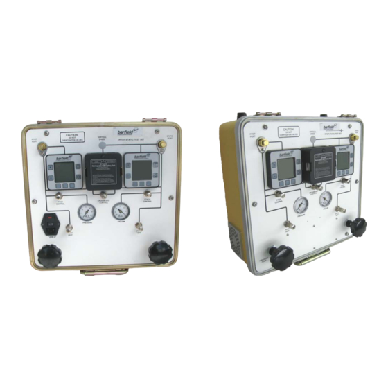
CHAPTER 1: GENERAL INFORMATION 1. TEST SETS DESCRIPTION The BARFIELD INC. 1811HA / GA (Figure 3) is a Pitot-Static Test Set, intended to test aircraft Pitot and Static Systems for leaks and to test the operation and calibration of airspeed, altimeter, rate of climb, and other vacuum or low pressure units. The Test Set is a portable unit enclosed in a fiberglass carrying case. -
Page 18: Physical Description Carrying Case
2. PHYSICAL DESCRIPTION A. Carrying Case The Tester comes with a fiberglass carrying case that contains upper and lower sections: The lower section supports the panel assembly. The upper section has sliding pin hinges for easy removal and is fitted with a shelf suitable for storing the manual, hoses and the power cable. -
Page 19: Front Panel
C. Front Panel Figure 5 identifies the components of the Test Set Front Panel, as listed in Table 2. Figure 4 1811GA / HA Front Panel a Sabena technics company ... - Page 20 Table 2 1811GA / HA Front Panel Items (Continuation) ITEM DESIGNATION DESCRIPTION FUNCTION Monitor pressure altitude at vacuum- - - - - - Altimeter static side of T/S. 1/8-27 NPT Female Port for connection to aircraft Static STATIC PORT Bulkhead Fitting System or other application Vacuum Source STATIC CONTROL...
-
Page 21: Power Information For 1811Ha
D. Power Information (1811HA Only) The Power Entry Module fulfills three user functions (from top to bottom in Figure 5): Allows easy replacement of blown fuses (refer to page 12 for fuses specifications). Allows turning power for pump ON () or OFF (O). Note: The end of the switch that is pressed inward, indicates which position is selected. - Page 22 THIS PAGE INTENTIONALLY LEFT BLANK 56-101-00184 / 00185 Rev. I Blank September 24, 2014 Page 10 of 56...
-
Page 23: Chapter 2: Specifications And Capabilities
CHAPTER 2: SPECIFICATIONS AND CAPABILITIES 1. PHYSICAL DATA A. Height: 11.5 in (29.2 cm) B. Width 15.5 in (39.4 cm) C. Depth: 15.5 in (39.4 cm) D. Weight * 26 lbs (12.0 kg) 1811GA 34 lbs (15.5 kg) 1811HA * (shipping weight) 2. -
Page 24: Input Power For 1811Ha
7. INPUT POWER (1811HA MODEL ONLY) 100 - 240VAC / 50 - 60 Hz / 60W Note: Input power functional at 400Hz, but not UL certified 8. FUSE PROTECTION (1811HA MODEL ONLY) Operating at 120VAC: 2 fuses, 1A each Operating at 240VAC: 2 fuses, 0.5A each Note: The 1811HA Test Set ships with 2 each, 1A (5mmx20mm) fuses installed. -
Page 25: Chapter 3: Operation
CHAPTER 3. OPERATION 1. THEORY OF OPERATION The 1811HA / GA Pitot-Static Test Sets (T/S) test the aircraft Pitot and Static Systems for leaks. The Tester is also used to operate and calibrate airspeed, altimeter, rate of climb, engine pressure ratio, manifold pressure indicators, and other vacuum or low pressure units. Panel mounted hand pumps are equipped with reservoir tanks to supply pressure and vacuum. -
Page 26: Power Supply Circuits
C. Power Supply Circuits The 1811HA can be powered from 100 - 240VAC / 50 - 60 Hz. The internal power supply automatically detects input voltage applied of 100 - 240VAC. 2. 1811GA PNEUMATIC SCHEMATIC DIAGRAM The 1811GA internal pneumatic connections are shown in Figure 6. PRESSURE TANK VACUUM TANK VERTICAL... -
Page 27: 11Ha Pneumatic Schematic
3. 1811HA PNEUMATIC SCHEMATIC DIAGRAM The 1811HA internal pneumatic connections are shown in Figure 7. VACUUM/PRESSURE ELECTRIC PUMP PRESSURE TANK VACUUM TANK VERTICAL SPEED STATIC PITOT PORT PORT AIRSPEED ALTIMETER STATIC PITOT CONTROL CONTROL CROSSBLEED CONTROL PRESSURE VACUUM GAUGE GAUGE PITOT STATIC PRESSURE PUMP... -
Page 28: Preliminary General
4. PRELIMINARY A. General The 1811HA / GA consists of a hand-operated vacuum pump and a hand-operated pressure pump. The pressure pump is single action developing pressure on the down stroke only while the vacuum pump is double action developing vacuum on both the up and down stroke. -
Page 29: Pretests
The VACUUM GAUGE (#9) will show the available vacuum (minimum 25 inHg) for the static vacuum source. After completing the test, return the internal electric PUMP SWITCH (#24) to OFF. 5. PRETESTS Note: To avoid incorrect results or damage to the aircraft or Test Set (T/S) instruments, the manufacturer recommends that the user pay particular attention to the following preliminary procedures. -
Page 30: Applying Leak Correction
C. Applying Leak Correction If the leak rate does not exceed 2 knots or 100 feet in 1 minute, determine the actual aircraft system leak rate by adding the observed rate obtained from a previous aircraft leak test to the recorded rate. D. -
Page 31: Static System Test
Note: The user may compare the aircraft airspeed with the T/S airspeed for calibration by applying T/S calibration card corrections when applicable. Close PITOT CONTROL (#19) fully CW. After the instrument indications stabilize, monitor the airspeed (#2) for one minute. The airspeed (value shown on the indicator) must not decrease by a value greater than 2 kts plus the leak rate (determined previously in the Pitot Pretest) of the Test Set. -
Page 32: Static Leak Test For Non-Pressurized Aircraft
B. Static Leak Test (for non-pressurized aircraft only) Note: When performing the Static Leak Test or if the aircraft airspeed indicator has a range of 150 knots (175 MPH) or less, do not exceed 1,000 ft increase above field level ambient. (During the test, both the aircraft and the T/S airspeed indicators increase as the altitude increases.) Caution:... -
Page 33: Negative Altitude Tests
Close the STATIC VENT (#10) fully (CW). Caution: If one of the following steps fails, close the STATIC CONTROL (#7) fully (CW). Gently, open the PITOT VENT (#17) to return system to ambient before disconnecting the T/S. Caution: If the T/S is used outside of the aircraft, monitor the VERTICAL SPEED INDICATOR (VSI) so that the aircraft VSI range is not exceeded. -
Page 34: Vertical Speed Indicator (Vsi) Operation
Note: If the airspeed pointer indication increases, the leak is in the pitot system. If the pointer decreases, the leak is in the static system. (3) After the test completes, gradually open CROSSBLEED CONTROL (#8) CCW fully. (4) Return system to ambient, by gradually opening the PITOT VENT (#17). Take care not to exceed vertical speed indicator range. -
Page 35: Combined Pitot / Static Test
When the vertical speed reference is no longer needed, close the VERTICAL SPEED (#3) control fully (CW). Note: Isolating the VSI at a pressure other than ambient, causes pressure to be “trapped”. As a result in later tests the T/S VSI (#4) could show descent (when paired with the Static System) even though the altitude is actually increasing. -
Page 36: Above Field Elevation Tests
If an airspeed test point is accidentally, exceeded do the following: Gently open the CROSSBLEED (#8) valve until the airspeed is 10 knots below the desired test value. (Some altitude change occurs.) Gently open the STATIC CONTROL (#7) valve to restore the altitude (#5) to a correct test point. -
Page 37: Returning The Pitot / Static Test Set To Ambient
Open STATIC CONTROL (#7) to raise the altitude to the next test point. (Use the CROSSBLEED CONTROL (#8) to maintain airspeed below the test point.) Once reaching the desired altitude, close both controls. (10) Repeat steps (3) through (9) until completing all airspeed tests at each desired altitude. -
Page 38: Machmeter Test
9. MACHMETER TEST A. Test Procedure Using the methods described in 8. COMBINED PITOT (AIRSPEED) STATIC (ALTITUDE) TEST, set an altitude (in feet) listed in the following table. Set the corresponding airspeed (in knots). Verify t`hat the MACH value obtained is the same as listed in the table for the settings. -
Page 39: Engine Pressure Ratio (Epr) Test
10. ENGINE PRESSURE RATIO (EPR) TEST A. Test Procedure Connect the PITOT PORT (#1) to the Pt7 (Hi) port of EPR to be tested. Connect the STATIC PORT (#6) to Pt2 (Lo) port of EPR to be tested. Using the methods described 8. COMBINED PITOT (AIRSPEED) STATIC... -
Page 40: Manifold Pressure Gauge Test
11. MANIFOLD PRESSURE GAUGE TEST A. Test Procedure Plug or cap PITOT PORT (#1). Connect STATIC PORT (#6) to manifold gauge to be tested. Close all T/S valves (#3, #7, #8, #10, #17, #19). Open the CROSSBLEED CONTROL (#8) fully and maintain it open. Verify that the ALTIMETER (#5) is set at 29.92 inHg (1013.3 mb). -
Page 41: Low Pressure Tests
12. LOW PRESSURE TESTS Note: The following test uses 0-12 PSI, 0-25 in-Hg or 1-340 in-H 0 ranges and is limited by T/S airspeed range. Refer to Table 6 for equivalent airspeed readings. A. Test Procedure (1) Connect PITOT PORT (#1) to pressure unit to be tested. (2) Close all T/S valves (#3, #7, #8, #10, #17, #19) CW. -
Page 42: Vacuum Tests
(4) Open PITOT CONTROL (#19) to establish desired reading on AIRSPEED (#2) for equivalent pressure as listed in Table 6. (5) Gradually open PITOT VENT (#17) CCW to lower airspeed reading or to return system to ambient. 13. VACUUM TESTS Note: The following test uses 0-12 PSI, 0-25 inHg or 1-340 inH 0 ranges and is limited by T/S airspeed and altimeter ranges. -
Page 43: Chapter 4: Valve Leak Test
CHAPTER 4. VALVE LEAK TEST 1. METERING VALVE ADJUSTMENT PROCEDURE Note: The following procedure is also released as IM150 (dated 7/6/88.) A. Valve Leak Test Caution: Before performing the Valve Leak test, inspect for system or instrument leakage. (Refer to the appropriate Aircraft Maintenance Manual for information and proper procedure.) Note: Read sections “A”... -
Page 44: Vacuum Vent Test
Fully close the "VACUUM VENT" and monitor both AIRSPEED INDICATOR and ALTIMETER: Note: If the ALTIMETER moves down scale, the leak is located at the "CROSSBLEED" valve. If the ALTIMETER does not move but the AIRSPEED continues to decrease, the leak is located at the "PRESSURE VENT"... -
Page 45: Resetting Needle Valve Positive Stop
Note: An increase of altitude of more then 100 ft. means the leak is located at the "VACUUM" valve. Repair leak before continuing. 2. RESETTING NEEDLE VALVE POSITIVE STOP Note: Before performing Valve Leak Test or Resetting the Needle Valve Positive Stop, inspect the entire system for leaks at locations other than valve seats, i.e., connections, general plumbing and instruments. - Page 46 THIS PAGE INTENTIONALLY LEFT BLANK 56-101-00184 / 00185 Rev. I Blank September 24, 2014 Page 34 of 56...
-
Page 47: Chapter 5: Inspection Recommendations
CHAPTER 5: INSPECTION RECOMMENDATIONS The manufacturer recommends that inspection be performed in the periods shown in Table 7. Table 7 Required Periodic Inspections / Recertification Intervals TIME PERIOD INSPECTION REQUIRED With Each Use Leak Test. Refer to “Pretest” Section on pages 17 and 18. For analog instrument configuration(s), refer to Analog Instrument 6 Months Specifications included in the Appendix of this manual. -
Page 48: Chapter 6: Shipping
CHAPTER 6: SHIPPING Use standard delicate electronic equipment packaging procedure when packing the Test Set for reshipment. To prevent damage from extreme atmospheric changes to the Test Set instruments, it is recommended that the STATIC VENT, CROSSBLEED CONTROL, AND PITOT VENT VALVES be in open position. -
Page 49: Chapter 7: Storage
CHAPTER 7: STORAGE A. Place a four ounce bag of desiccant inside the container B. Close and latch the cover. C. Store in a cool dry place. Note: Should the Test Set become exposed to moisture or very high humidity, dry as soon as possible and temporarily store in dehumidified area. - Page 50 THIS PAGE INTENTIONALLY LEFT BLANK 56-101-00184 / 00185 Rev. I Blank September 24, 2014 Page 38 of 56...
-
Page 51: Appendix: Analog Instruments Specifications
APPENDIX ANALOG INSTRUMENT SPECIFICATIONS Note: For information on compliance with FAR 91-411, refer to Barfield document, 60-101-00150. SECTION 1: ALTIMETER SECTION 2: AIRSPEED SECTION 3: VERTICAL SPEED INDICATOR 56-101-00184 / 00185 Rev. I Appendix September 24, 2014 Page 39 of 56... -
Page 52: Altimeter
SECTION 1: ALTIMETER The following engineering specification (Document # 23-338-00001) details the performance requirements of the pressure sensitive altimeters used in Barfield Inc. manufactured ground test equipment. 56-101-00184 / 00185 Rev. I Appendix September 24, 2014 Page 40 of 56... - Page 54 Engineering Specification Barfield, Inc Title: Altimeter, Ground Support Equipment 4101 NW 29 Street Miami Florida 33142 Drawing No: 23‐338‐00001 Page 2 of 5 1. Purpose: To specify performance requirements for Pressure Sensitive Altimeters for use in B.I.C. manufactured ground support test equipment. 2. Scope: This PRODUCT STANDARD SPECIFICATION covers two basic types of instruments as...
- Page 55 Engineering Specification Barfield, Inc Title: Altimeter, Ground Support Equipment 4101 NW 29 Street Miami Florida 33142 Drawing No: 23‐338‐00001 Page 3 of 5 5. Performance Requirements: All units are required to meet the following performance requirements before installation in any ground support test equipment. Case Leak: A pressure equivalent to 18,000 ft. within the case shall not result in leakage exceeding 20 ft ( 100 ft when installed in Test Set ) per minute.
- Page 56 Engineering Specification Barfield, Inc Title: Altimeter, Ground Support Equipment 4101 NW 29 Street Miami Florida 33142 Drawing No: 23‐338‐00001 Page 4 of 5 the test reading is taken. After the reading has been taken, the pressure shall be further increased at the above rate until atmospheric pressure is reached. The reading of the altimeter at either of the two test points shall not differ from the reading of the altimeter for the corresponding altitude in the scale error test by more than the tolerance specified in the corresponding table.
- Page 57 Engineering Specification Barfield, Inc Title: Altimeter, Ground Support Equipment 4101 NW 29 Street Miami Florida 33142 Drawing No: 23‐338‐00001 Page 5 of 5 ALTITUDE ALTIMETER ALTITUDE ALTIMETER (FEET) ERROR ± (FEET) ERROR ± -1,000 -1,000 1,000 1,000 1,500 1,500 2,000 2,000 3,000 3,000 4,000 4,000 6,000 6,000 8,000 8,000 10,000 10,000 12,000 12,000 14,000...
-
Page 58: Airspeed
SECTION 2: AIRSPEED The following engineering specification (Barfield Document No. 23-336-00025) details the performance requirements of the pitot static pressure type airspeed indicators for use in Barfield Inc. manufactured ground support test equipment. 56-101-00184 / 00185 Rev. I Appendix September 24, 2014... - Page 60 Engineering Specification Barfield, Inc Title: Airspeed, Ground Support Equipment 4101 NW 29 Street Miami Florida 33142 Drawing No: 23‐336‐00025 Page 2 of 5 1. Purpose: To specify performance requirements for Pitot Static Pressure Type of Airspeed Indicators for use in B.I.C. Manufactured ground support test equipment. 2. Scope: This Product STANDARD SPECIFICATION covers two (2) basic types of airspeed indicators...
- Page 61 Engineering Specification Barfield, Inc Title: Airspeed, Ground Support Equipment 4101 NW 29 Street Miami Florida 33142 Drawing No: 23‐336‐00025 Page 3 of 5 Vibration: With pressure applied, sufficient to give half scale deflection, the instrument shall be subjected to vibrations of all frequencies within the appropriate ranges specified. Pointer Position: The position of the pointer without any pressure applied shall rest on the lowest airspeed on the dial with the exception of P/N's 336-00001,336-00001R and 336- 00004.
- Page 62 Engineering Specification Barfield, Inc Title: Airspeed, Ground Support Equipment 4101 NW 29 Street Miami Florida 33142 Drawing No: 23‐336‐00025 Page 4 of 5 P/N 336-00004: READING TOLERANCE READING TOLERANCE (Knots) (Knots) (Knots) (Knots) ± 3.0 ± 4.0 ± 3.0 ± 4.0 ± 3.0 ± 5.0 ± 3.0 ± 5.0 ± 3.0 ± 5.0 ± 3.0 ±...
- Page 63 Engineering Specification Barfield, Inc Title: Airspeed, Ground Support Equipment 4101 NW 29 Street Miami Florida 33142 Drawing No: 23‐336‐00025 Page 5 of 5 P/N 336-00006: READING TOLERANCE READING TOLERANCE (Knots) (Knots) (Knots) (Knots) ± 5.0 ± 4.0 ± 5.0 ± 4.0 ± 3.5 ± 4.0 ± 3.0 ± 4.0 ± 3.0 ± 4.0 ± 3.0 ±...
-
Page 64: Vertical Speed Indicator
SECTION 3: VERTICAL SPEED INDICATOR The following engineering specification (Document 23-337-00025) details performance requirements of the pressure actuated vertical speed indicators used in Barfield manufactured ground support test equipment test equipment. 56-101-00184 / 00185 Rev. I Appendix September 24, 2014... - Page 66 Engineering Specification Barfield, Inc Title: Vertical Speed Indicator, Ground Support 4101 NW 29 Street Equipment Miami Florida 33142 Drawing No: 23‐337‐00025 Page 2 of 4 1. Purpose: To specify performance requirements for pressure actuated vertical speed indicators for use in B.I.C. manufactured ground support test equipment. 2. Scope: This engineering specification covers four (4) basic types of direct indicating instruments as...
- Page 67 Engineering Specification Barfield, Inc Title: Vertical Speed Indicator, Ground Support 4101 NW 29 Street Equipment Miami Florida 33142 Drawing No: 23‐337‐00025 Page 3 of 4 Friction: A test shall be performed to ascertain friction. In the time intervals at which the lag time is measured, the pointer shall move smoothly towards zero (while no vibration is...
- Page 68 Engineering Specification Barfield, Inc Title: Vertical Speed Indicator, Ground Support 4101 NW 29 Street Equipment Miami Florida 33142 Drawing No: 23‐337‐00025 Page 4 of 4 TABLE 1 SCALE ERROR TOLERANCE TYPES I AND II (Ranges: 0-2,000 and 0-3,000 feet per minute) Test Rate Ascent and Descent Tolerance Feet Per Minute Feet Per Minute 1,000 1,500** 2,000...
Need help?
Do you have a question about the 1811GA Series and is the answer not in the manual?
Questions and answers