Table of Contents
Advertisement
To buy, sell, rent or trade-in this product please click on the link below:
http://www.avionteq.com/Barfield-TT1000A-Turbine-Temperature-Test-Set-PN-101-00901.aspx
TT-1000A
Corporate Headquarters
4101 Northwest 29th Street
Miami, Florida 33142
www.barfieldinc.com
Email: gsesales@barfieldinc.com
www.avionteq.com
TURBINE TEMPERATURE TEST
SET
USER INSTRUCTION MANUAL
M/N: TT-1000A
P/N:101-00901
Doc. P/N: 56-101-00901
Revision D
April 24, 2013
__________________________________
BARFIELD, INC.
Advertisement
Table of Contents

Related Manuals for barfield TT-1000A


Summary of Contents for barfield TT-1000A
- Page 1 To buy, sell, rent or trade-in this product please click on the link below: http://www.avionteq.com/Barfield-TT1000A-Turbine-Temperature-Test-Set-PN-101-00901.aspx www.avionteq.com TURBINE TEMPERATURE TEST TT-1000A USER INSTRUCTION MANUAL M/N: TT-1000A P/N:101-00901 Doc. P/N: 56-101-00901 Revision D April 24, 2013 __________________________________ BARFIELD, INC. Corporate Headquarters 4101 Northwest 29th Street Miami, Florida 33142 www.barfieldinc.com...
- Page 2 DISCLAIMER BARFIELD INC., neither a vendor nor supplier of Turbine Temperature Systems or an airframe manufacturer, has no control over calibration figures or procedures. A variant between actual and those recommended may exist, however, information presented is correct to the best of our knowledge at the time of publication and is presented for reference only.
- Page 3 OWNER WARRANTY REGISTRATION CARD to Barfield in order to validate the warranty and to ensure that you will receive updated information when published. You MUST have your name and address on file at Barfield as a registered user of this equipment, to be able to obtain the service covered by the warranty.
- Page 4 56-101-00901-D Page iv...
- Page 5 REVISION RECORD REV. ECO # REV. DATE DESCRIPTION OF CHANGE May 5, 1995 Initial Release Updated to latest format. Added List of February 16, 2002 Figures/Tables page. Updated to latest format; specifications section 260-00890 January 27, 2012 changes. Added instructions for using 45vdc voltage 260-00970 April 24, 2013 converter.
- Page 6 A Return Maintenance Authorization (RMA) number will be assigned during this call, to keep track of the shipment and the service. BARFIELD PRODUCT SUPPORT DIVISION Mailing / Shipping Address:...
-
Page 7: Table Of Contents
TABLE OF CONTENTS Contact Information Attention Warranty Information Revision Record Maintenance and Repair Information Table of Contents Page DESCRIPTION Purpose of Manual........................... 1 General Description ......................... 1 Switching Functions ......................... 2 OPERATION General Operating Instructions ...................... 4 System Lead Resistance Test Procedure ..................7 Thermocouple Resistance Test Procedure ................... - Page 8 LIST OF FIGURES AND TABLES SECTION FIGURE / TABLE TITLE PAGE TT-1000A FRONT PANEL LAYOUT VOLTAGE CONVERSION 16Ω INDICATOR TEST CONVERSION TABLE THERMOCOUPLE LINEARIZATION TABLE REFERENCE JUNCTION COMPENSATION TABLE ERROR TABLE 56-101-00901-D Page viii...
-
Page 9: Description
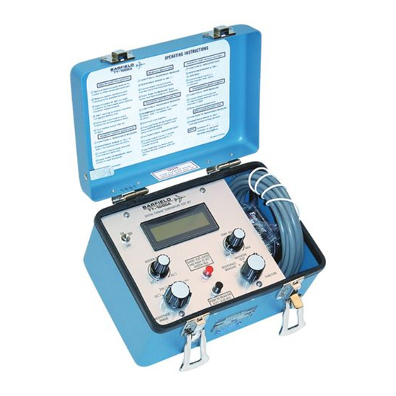
(Refer to Figure 1.) Manufactured by: Barfield Inc. B. This manual is released to address the TT-1000A which is designed to test and calibrate Chromel-Alumel (CH-AL) temperature indicating systems. 2. GENERAL DESCRIPTION The TT-1000A provides the means for quickly troubleshooting aircraft temperature indicating systems. -
Page 10: Switching Functions
NOTE: For personnel without experience, it is advisable to become familiar with this publication, the TT-1000A, and the equipment with which it is to be used BEFORE performing any test or checks. 3. SWITCHING FUNCTIONS (Refer to Figure. 1) A. - Page 11 G. The "SYSTEM RES." control knob (8), a ten turn potentiometer used to adjust system lead resistance 2 to 25 Ω, when test leads are shorted and the RED pushbutton is depressed. TT-1000A FRONT PANEL LAYOUT Figure 1 56-101-00901-D Page 3 of 19...
-
Page 12: Operation
B. Preparation for Use: (1) Battery Installation / Replacement; (a) Place the TT-1000A on a clean area. (A clean cloth or paper pad placed next to the TT-1000A to receive the panel is desirable.) Remove the four corner panel screws. Lift the panel high enough (approx. 2 in.) to disconnect the 45 volt battery connector located under "ON/OFF"... - Page 13 (2) Perform the TT-1000A Battery check prior to testing as follows: (a) To check the 45 volt battery used for insulation testing, rotate the "FUNCTION" selector switch to "RESISTANCE MEASURE" position and the "RESISTANCE RANGE"...
- Page 14 (d) Depress the BLACK pushbutton switch. If "BAT" is displayed replace the six 1.5 volt batteries as outlined above. NOTE: After removal, test each cell individually (under load) as one or more defective cells mixed with good ones may produce a low battery warning.
-
Page 15: System Lead Resistance Test Procedure
NOTE: Resistance must be within manufacturer's specifications. If results are slightly outside limits, repeat entire procedure to insure test failure is not due to human error. H. Place "ON/OFF" switch to "OFF", disconnect the TT-1000A and return aircraft to original configuration. 56-101-00901-D... -
Page 16: Thermocouple Resistance Test Procedure
NOTE: Resistance must be within manufacturer's specifications. If results are slightly outside limits, repeat entire procedure to insure test failure is not due to human error. H. Place "ON/OFF" switch to "OFF", disconnect the TT-1000A and return aircraft to original configuration. 56-101-00901-D... -
Page 17: Insulation Testing Procedure
2 MΩ. (Refer to the Aircraft Maintenance Manual for low limit.) NOTE: Resistance to ground must not be less than manufacturer's specifications. F. Place "ON/OFF" switch to "OFF", disconnect the TT-1000A and return aircraft to original configuration. 56-101-00901-D... -
Page 18: Indicator Test Procedure
F. Disconnect aircraft thermocouple leads from temperature indicator. G. Connect test lead clips to indicator terminals. OBSERVE POLARITY. Alumel is negative (-) and connects to the TT-1000A BLACK clip: Chromel is positive (+) and connects to the TT-1000A RED clip. - Page 19 J. Place "ON/OFF" switch to "OFF", disconnect the TT-1000A and return aircraft to original configuration. TT-1000A INDICATOR 1000 1109 1217 1325 1432 1538 1642 1746 1848 1949 16 Ω INDICATOR TEST CONVERSION TABLE (Mod "B" ONLY) Table 1 56-101-00901-D Page 11 of 19...
-
Page 20: Potentiometer Or Servo Type Indicator Test Procedure
Manual.) (2) Disconnect electrical connector at rear of indicator. (3) Connect TT-1000A leads to probe pins sized to fit chromel and alumel pin sockets of aircraft plug removed from indicator. (4) Follow paragraph 2, System Lead Resistance Test Procedure, steps C. - Page 21 (4) Rotate the "RESISTANCE RANGE" selector to 2 MΩ (0 Ω SYS. RES.) (5) Connect test lead clips to indicator leads OBSERVING POLARITY. Alumel is negative (-) and connects to the TT-1000A BLACK clip: Chromel is positive (+) and connects to the TT-1000A RED clip.
-
Page 22: Temperature Measurement Test Procedure
HAVE TWO TERMINAL POSTS OR TERMINAL SCREWS. B. Connect test lead clips to thermocouple leads OBSERVING POLARITY. Alumel is negative (-) and connects to the TT-1000A BLACK clip: Chromel is positive (+) and connects to the TT-1000A RED clip. Units with Mod "B" incorporated must connect to only one thermocouple lead pair at a time. -
Page 23: Specifications And Capabilities
SPECIFICATIONS AND CAPABILITIES 1. PHYSICAL DATA A. Length - 8.0 in (20.3 cm) B. Width - 5.5 in (14.0 cm) C. Height - 5.0 in (12.7 cm) D. Weight - 4.0 lbs (1.8 kg) 2. SPECIFICATIONS A. Temperature Measurement: (1) Type: K (CH-AL Thermocouple). (2) Range: 0 to 1000 C certified, -25 to +1100 C extended. -
Page 24: Capabilities
C. Insulation: (1) Range; 0-1.999 MΩ in 1 kΩ increments. (2) Accuracy; ± 3% of reading ± 0.003MΩ. (3) Excitation; 45V DC nominal. D. Simulated System Resistance: (1) Adjustment Range; Less than 2.0 Ω to greater than 25 Ω. (2) Fixed Setting; Less than 0.1 Ω. 3. - Page 25 NIST CONFORMITY: (TEST CLIP LINEARIZATION) RANGE ERROR ± -25 TO -21 LESS THAN 2.0 -20 TO 0 LESS THAN 1.0 0 TO 90 LESS THAN 0.6 91 TO 169 LESS THAN 1.0 170 TO 1000 LESS THAN 0.6 * 1001 TO 1025 LESS THAN 1.0 * 1026 TO 1050 LESS THAN 2.0...
-
Page 26: Recertification
* REFERENCE JUNCTION COMPENSATION TEMPERATURE ERROR ± 0 TO 30 LESS THAN 0.1 31 TO 40 LESS THAN 0.3 41 TO 50 LESS THAN 0.6 * AT TEST CLIPS REFERENCE JUNCTION COMPENSATION Table 3 0 TO 1000 C AT 25 C AMBIENT ERROR SOURCE ERROR ±... -
Page 27: Shipping
TT-1000A. It is also recommended that the TT-1000A and its carrying case be carefully inspected for damage. If damaged, immediately notify the carrier and the manufacturer.
Need help?
Do you have a question about the TT-1000A and is the answer not in the manual?
Questions and answers