
Related Manuals for Yamaha 6X9 DIGITAL ELECTRONIC CONTROL


Summary of Contents for Yamaha 6X9 DIGITAL ELECTRONIC CONTROL
- Page 1 6X9 DIGITAL ELECTRONIC CONTROL (DEC) (QUINT ENGINE) OPERATION MANUAL LIT-18626-13-55 6X9-28199-90 Read this manual carefully before operation.
- Page 2 Read this manual carefully before operating this system. Keep this manual onboard in a waterproof bag when boating.
- Page 3 Therefore, while this manual contains the most current product information available at the time of printing, there may be minor discrepancies between the actual system and this manual. If you have any questions about the operation of your 6X9 Digital Electronic Control system, please consult a Yamaha dealer.
-
Page 4: Table Of Contents
CONTENTS Alert message information ...........1 General information ..............6 List of abbreviations ................6 Read labels and related manuals ............. 6 ELECTRONIC KEY SWITCH (EKS) ........7 Basic information ................7 POWER switch ................. 10 START/STOP switch ................ 11 All START/STOP switch ..............11 Engine shut-off switch .............. - Page 5 Joystick (Upgradable) ............49 Basic information ................49 Joystick ..................... 53 Maneuvering with the joystick ..............54 Joystick switch ................55 Joystick calibration ................. 55 SetPoint switches (STAYPOINT/DRIFTPOINT/FISHPOINT) ..56 Plus (+) button/minus (-) button ............. 59 SetPoint functions ................60 Changing the position of your boat in SetPoint mode ....62 Autopilot Operation ............64 Basic information ................
-
Page 6: Alert Message Information
Alert message information This section contains 6X9 Digital Electronic Control (DEC) system alert information that will be dis- played on the MFD. Refer to MFD operation manual for additional information. The MFD will display a window and alert icons to notify the operator when abnormalities in the 6X9 Digital Electronic Control system occur. - Page 7 - Port Engine - Confirm Check battery and wiring. Displayed if a problem occurred in 6X9 Digital Electronic Control system. Turn off electric power, wait 20 seconds, and then turn electric power on again. CHECK SYSTEM - Port Engine - System configuration fault.
- Page 8 Displayed if all engines’ steering systems do not move properly. Consult a Yamaha dealer. STEERING MALFUNCTION - Port Engine - Shift to neutral! Emergency steer procedure: Use engine’ s manual override lever to steer. Confirm Consult Yamaha dealer. Displayed if all engines’ steering systems do not move properly. Consult a Yamaha dealer.
- Page 9 Other notifications Displayed if running a single engine for more than one hour. Start all engines to recharge the batter- ies. Battery Charge Low Confirm Start all engines to recharge Displayed if GPS signal is interrupted and speed control stopped functioning. GPS is unstable.
- Page 10 Displayed when deceleration during TRACK POINT has finished. (When boat does SetPoint control at final destination) Deceleration finished. Confirm To activate Set Point, shift all levers to neutral. Displayed when TRACK POINT was turned on after setting route on MFD with no final destination information.
-
Page 11: General Information
Read labels and related manuals Before operating or working on this system: • Read all labels carefully on the 6X9 Digital Electronic Control (DEC) system components. • Read this manual thoroughly and see other related manuals for outboard motors, MFD and boats for their basic operations. -
Page 12: Electronic Key Switch (Eks)
Basic information ELECTRONIC KEY SWITCH (EKS) Basic information The EKS consists of the EKS panel and the key fobs. EKS functions: EKS locking/unlocking using key fobs, power switch ON/OFF and engine starting and stopping. Pressing the All start/stop switch will start or stop all engines. Key fob Key fob HOW TO UNLOCK (Pattern 1) - Page 13 Basic information Main station 2nd station Lock indicator POWER switch POWER switch Pushing the “POWER” switch turns the power to each engine ON and OFF. START/STOP switch (ALL) ALL START/STOP switch Pushing the ALL “START/STOP” switch starts and stops all engines. POWER panel ALL START/STOP panel Main / 2nd station...
- Page 14 • When operating or stopping the boat, be sure to carry the key fob with you and be careful not to lose it. • If any key fob is lost, be sure to have a Yamaha dealer delete the registration of the lost key num- ber for security reasons.
-
Page 15: Power Switch
POWER switch POWER switch How to unlock (Pattern 2) 1. Hold the key fob within 5 m of the Pushing the power switch turns the power to POWER panel. each engine ON and OFF. When the power is ON, the LED will be illuminated. 2. -
Page 16: Start/Stop Switch
2. Press the POWER switch. TIP: If you push the POWER switch, and the beep sounds more than twice, request an inspec- tion and repairs at a Yamaha dealer. POWER panel Number of beeps Recognition succeeded More than ... -
Page 17: Engine Shut-Off Switch
Engine shut-off switch Engine shut-off switch Smart key settings The clip must be attached to the engine shut- Password card off switch for the engines to run. The cord The key fob is provided with two cards on should be attached to a secure place on the which are written its factory default. -
Page 18: Changing The Password
Smart key settings Changing the password You can add a new key fob or change the password to unlock the system if the smart key is lost. TIP: • The procedure to change the password in “How to set (how to enter setting mode)”, and when the recognition succeeded beep sounds, move to “How to set (how to set passwords)”. - Page 19 Smart key settings 5. After the first digit is set, press the POWER switch to start setting the second digit of your pass- word. 6. Set the second digit “” of the password. Press the POWER switch, while the beep is beeping, when it reaches the number of beeps that is equal to the number you want for this digit of your password.
- Page 20 Smart key settings 10. Set the fourth digit “” of the password. Press the POWER switch, while the beep is beeping, when it reaches the number of beeps that is equal to the number you want for this digit of your password. ...
-
Page 21: Special Mode
Smart key settings Example of how to set a password Example) To set “3468” as the password. : Beep 10 (0) First digit ... - Page 22 Smart key settings How to set (how to set passwords) 1. The password input mode activates and a beep sounds. Number of beeps When recognition succeeds 2. Press the POWER switch once to start the password beep. 3. Set the first digit “” of the password. Press the POWER switch, while the beep is beeping, when it reaches the number of beeps that is equal to the number you want for this digit of your password.
- Page 23 Smart key settings 6. After the second digit is set, press the POWER switch to start setting the third digit of your pass- word. 7. Set the third digit “” of the password. Press the POWER switch, while the beep is beeping, when it reaches the number of beeps that is equal to the number you want for this digit of your password.
- Page 24 Smart key settings TIP: • A short beep sounds 10 times according to the numbers in the password (password: 1, 2, 3, 4, 5, 6, 7, 8, 9, 0). Number of First Second Third Fourth Fifth Sixth Seventh Eighth Ninth Tenth beeps Password...
-
Page 25: Adding A New Key Fob
Smart key settings Adding a new key fob 5. Press the lock or unlock button on the new key fob that you want to register one If you want to add a new key fob, you can use time. the following procedure to do it. 1. -
Page 26: Replacing The Battery In The Key Fob
Replacing the battery in the key fob Replacing the battery in the key fob After the recognition succeeded beep sounds one time, if the beep sounds 10 times in a row, then replace the battery in the key fob. Recognition ... - Page 27 Replacing the battery in the key fob Step 1 Step 2 Step 3 Step 4 To assemble, do the procedure in reverse. 1. O-ring 2. Battery Recommended battery: CR2025...
-
Page 28: Information Required By Radio Laws
Information required by radio laws Information required by radio laws 1. USA (FCC), Canada (ISED) FCC CAUTION Changes or modifications not expressly approved by the party responsible for compliance could void the operator’s authority to operate the equipment. FCC/ISED This device complies with part 15 of FCC Rules and Innovation, Science and Economic Develop- ment Canada’s licence-exempt RSS(s). - Page 29 Information required by radio laws Ar šo MITSUBISHI ELECTRIC CORPORATION, [DA] Hermed erklærer MITSUBISHI ELECTRIC COR- [LV] HIMEJI WORKS deklarē, ka radioiekārta Smart Key- Danish PORATION, HIMEJI WORKS, at radioudstyrstypen Latvian less System (SKESAE-01,SKESAE-02) atbilst Smart Keyless System (SKESAE-01,SKESAE-02) Direktīvai 2014/53/ES. er i overensstemmelse med direktiv 2014/53/EU.
- Page 30 Information required by radio laws 1. Serbia 2. Ukraine Україна справжнім MITSUBISHI ELECTRIC CORPORATION, HIMEJI WORKS заявляє, що тип радіообладнання (SKESAE-01, SKESAE-02) відповідає Технічному регламенту радіообладнання. Повний текст декларації про відповідність доступний на веб-сайті за такою адресою: http://www.mitsubishielectric.com/bu/automotive/doc/ukr.html 3. Moldova Prin prezenta, MITSUBISHI ELECTRIC CORPORATION, HIMEJI WORKS declară...
- Page 31 Information required by radio laws 6. Jamaica This product has been Type Approved by Jamaica: SMA -SKESAD-01 / SKESAD-02. 7. South Africa...
-
Page 32: Remote Control Box
Remote control box The remote control box, and its lever and switches, allows you to control the engines and maneuver your boat. 11 12 1. Remote control levers 7. Speed control switch 2. Station selector switch 8. LED 3. DEC alert indicator 9. -
Page 33: Dec Alert Indicator
Moving the lever farther opens the throttle, or accelerator operations, and consult about and the engine will begin to accelerate. an inspection and repairs at a Yamaha dealer. 1. Shift 2. Fully closed 3. - Page 34 Remote control levers Lever operation By moving both remote control levers, the boat can be maneuvered as shown below. A. Lever operation B. Boat direction and turning force (The size of the arrow is proportional to the turning force.) C. Propulsion...
-
Page 35: Adjusting The Friction Of The Levers
Adjusting the friction of the levers Adjusting the friction of the levers The effort to move the remote control levers can be adjusted to suit the operator preference. • If the effort to move the remote control levers is too loose, the remote control levers may move too quickly, which may cause an accident. - Page 36 Adjusting the friction of the levers Install the front cover and top cover How to adjust To adjust the effort needed to move the Install remote control levers, remove the front cover 1. Hook the hooks on the front of the top and top cover.
- Page 37 Adjusting the friction of the levers 4. Hook the hooks on the bottom of the front cover, and then press on the hooks on the top of the front cover to insert them. Step 1 Step 2 Step 3 Step 4...
-
Page 38: Adjusting The Detent Of The Levers
Adjusting the detent of the levers Adjusting the detent of the levers The movement of the remote control levers and click felt when shifting can be adjusted to suit the operator’s preference. • If the movement of the remote control levers and the click felt when shifting are too loose, the remote control levers may move too quickly, which may cause... - Page 39 Adjusting the detent of the levers Click felt when shifting Click felt when shifting Side cover Side cover STBD PORT a. Lighter b. Heavier Install the side covers Install 1. Insert the side cover hook “1” into the hole “2” on the remote control. 2.
-
Page 40: Neutral Hold Switch
Neutral hold switch Neutral hold switch When activated, the neutral hold switch allows opening the throttles of all engines, without engaging forward or reverse gear. How to operate 1. Move the remote control levers to the N position. 2. When the “NEUTRAL HOLD” switch is pressed, the beep sounds and the LED turns on. 3. - Page 41 Single lever switch How to operate The beep sounds and the LED turns on when you put the left and right remote control levers in the N position and press the “SINGLE LEVER” switch. 1. Single lever switch 2. LED...
-
Page 42: Center Engine Switch
CENTER engine switch How to release The beep sounds and the LED turn off when you put the remote control lever in the N position and press the “SINGLE LEVER” switch. 1. Single lever switch 2. LED CENTER engine switch When you want to move slowly, enabling the center engine switch allows you to do shift and throttle operations while running only the center engines (CENTER PORT/CENTER STBD). - Page 43 CENTER engine switch Example 1. CENTER engine switch 2. LED...
- Page 44 CENTER engine switch How to release The beep sounds and the LED turn off when you put the remote control levers in the N position and press the “CENTER ENGINE” switch. TIP: Cannot be released unless all the remote control levers are in the N position. 1.
-
Page 45: Speed Control
Speed control Speed control How to operate (joystick operations) 1. Set the remote control levers in any posi- Enabling the speed control switch allows you tion. to maintain a speed or make small speed Setting conditions adjustments to the engine speed and boat Forward: From the F position to an speed (GPS). -
Page 46: Station Selector Switch (For Dual Station)
Station selector switch (for dual station) How to release 3. You can do operations from the station 1. When the remote control levers are oper- that you enabled. ated, the beep sounds and the LED turn off. TIP: • The disabled station can only start and stop the engines. - Page 47 Power trim/tilt (PTT) switch • Be sure all people are clear of the out- board motors when adjusting the trim angle. There is a risk of serious injury if anyone is crushed between the engines and the clamp brackets during trimming or tilting.
-
Page 48: Trim Assist All
Trim Assist All How to set the PTT The PTT switches (STBD/PORT) can be used by setting them to any button position on the MFD. On the MFD, first select “Boat Control Setting”, and then select “PTT Switch”. After that, select the button you like and decide how it operates. -
Page 49: Trim Assist Center
Trim Assist Center TIP: • The engines must not be running when the desired speed and percentage of trim are entered into the gauge. It is recommended that the boat be water-tested to determine the optimum trim positions at specific engine speeds for your operating conditions prior to entering these settings. - Page 50 Trim Assist Center TIP: To configure and enable “Set CNTR Trim” function, “Set ALL Trim” setting has to be completed first. 1. From the “Engine Menu”, select “Trim Assist”. 4. Enter your preferred engine speed. Tap “Done” to confirm. 2. Select the position (1–5) you are setting. TIP: •...
- Page 51 Trim Assist Center 8. Set the desired amount of trim angle in percentage. Tap “Done” to confirm. 9. Tap “Back” to go back to the “Engine Menu” screen. 10. To change the percentage of trim angle for the remaining positions, 1–5, repeat steps 2–8.
-
Page 52: Autopilot (Upgradable)
Autopilot (Upgradable) Autopilot The Autopilot, which has four modes, is an automatic piloting function that assists with steering and throttle operations to keep the boat moving to a desired point or heading. The Autopilot system is a device that assists with steering. The captain is responsible for safe navi- gation, and should carefully monitor his boat while underway. -
Page 53: Heading Sensor Operation
Heading Sensor Operation Heading Sensor Operation 3. Point the bow leewards / towards drifting direction to reduce inaccuracy caused by Calibrate the compass before using the Auto- the boat drifting. Perform Set North pilot or SetPoint functions. Calibration according to the on-screen instructions until you see “Calibration Heading Sensor Calibration Status: Success”. -
Page 54: Joystick (Upgradable)
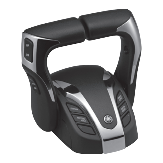
Basic information Joystick (Upgradable) Basic information Joystick The joystick control allows you to control the throttles and steering, and to shift the engines at low speeds. DRIFTPOINT switch STAYPOINT switch Plus (+) button Minus (-) button JOYSTICK switch FISHPOINT switch JOYSTICK LEVER Joystick lever By moving the joystick left, right, forward, reverse, or diagonally, you can move the boat in that direction. - Page 55 Basic information JOYSTICK switch JOYSTICK switch Enabling the joystick switch allows you to operate the boat at low speeds when leaving or arriving at a dock. HOW TO START HOW TO RELEASE Lateral Assist Lateral Assist ON/OFF setting (Multi engine only) This function automatically corrects the deviation between the Joy Stick operation and the boat movement in JOYSTICK mode.
- Page 56 Basic information SetPoint function SetPoint function Enabling the various switches allows you to do the following operations. • While the SetPoint function is enabled, the engines are operated automatically, as needed, to maintain the boats position or heading. Do not enable this function when people are in the water, or if other boats or obstacles are nearby.
- Page 57 Basic information FISHPOINT FISHPOINT (Bow/Stern) Keeps the bow or stern heading into the wind or current. This mode is suitable for fishing from a fixed point. Shifting and engine speed are restricted so the operating sounds do not scare away the fish. Enabling the FISHPOINT switch (bow) in the multifunction display keeps the bow heading into the wind or current.
-
Page 58: Joystick
Joystick Joystick The joystick control allows you to control the throttles and steering, and to shift the By moving the joystick left, right, forward, engines at low speeds. reverse, or diagonally, you can move the boat in that direction. When you release the joy- stick, it returns to the neutral (N) position. -
Page 59: Maneuvering With The Joystick
Joystick Maneuvering with the joystick A. Joystick operation B. Boat direction... -
Page 60: Joystick Switch
Joystick switch Joystick switch Enabling the joystick switch allows you to operate the boat at low speeds when leaving or arriving at a dock. How to operate 1. While the engine is running, put the remote control levers and joystick in the N position. -
Page 61: Setpoint Switches (Staypoint/Driftpoint/Fishpoint)
SetPoint switches (STAYPOINT/DRIFTPOINT/FISHPOINT) How to release TIP: 1. Press the joystick switch. • When calibrating the joystick, maneuver the boat safely in water where there are no obstacles. Avoid doing calibrations in high seas or strong winds, which could affect the results of the calibrations. - Page 62 SetPoint switches (STAYPOINT/DRIFTPOINT/FISHPOINT) • FISHPOINT switch How to release If you want to end the operation, do any of • Enabling the FISHPOINT switch (bow) the following. keeps the bow heading into the wind or • Press the switch you enabled. (LED turn current.
- Page 63 SetPoint switches (STAYPOINT/DRIFTPOINT/FISHPOINT) Lateral Assist (Multi engine only) This function automatically corrects the devi- ation between the joystick operation and the boat movement in joystick mode. Lateral assist ON/OFF setting Menu>Boat Set>Joystick and Set Point> Lateral Assist TIP: Default is OFF.
-
Page 64: Plus (+) Button/Minus (-) Button
Plus (+) button/minus (-) button Plus (+) button/minus (-) button Enabling the SetPoint or the joystick switch allows you to adjust the maximum engine speed and to adjust the thrust level. How to operate (when SetPoint is enabled) 1. While SetPoint is enabled, each time you press the plus (+) button the engine speed increases; each time you press the minus (-) button the engine speed decreases. -
Page 65: Setpoint Functions
SetPoint functions SetPoint functions • While the SetPoint function is enabled, the engines is operated automatically, as needed, to maintain the boats position or heading. Do not enable this function when people are in the water, or if other boats or obstacles are nearby. There is a risk of collision with the propeller or boat, which are moving for adjustments. - Page 66 SetPoint functions Maximum Wind and cur- engine speed rent direction, Mode setting Remarks and maintained (Plus (+)/minus orientation (-) buttons) DRIFTPOINT Thrust level The engine being Keeps only the boat’s Lv0–5 controlled switches heading, while the boat according to the thrust can drift diagonally with level.
-
Page 67: Changing The Position Of Your Boat In Setpoint Mode
Changing the position of your boat in SetPoint mode Changing the position of your boat in SetPoint mode You can change your boat’s heading or move its position while SetPoint mode is operating. If you want to move the current position of your boat forward, reverse, left, or right tilt the joystick. To change the heading, twist the joystick. - Page 68 Changing the position of your boat in SetPoint mode The orientation of the changes to the movement or heading of the boat vary depending on the mode of the SetPoint function. STAYPOINY FISHPOINT DRIFTPOINT...
-
Page 69: Autopilot Operation
You can adjust the sensitivity speed level of the outboard motors while Autopilot is being used. Faster Level 5 Level 4 Level 3 Level 2 Level 1 Slower TIP: ・If the rudder angle is hunting while in Autopilot, lower the sensitivity speed level. ・ Sensitivity speed level can also be adjusted via compatible Yamaha displays. - Page 70 Basic information HEADING HOLD HEADING HEADING HOLD switch HOLD This mode keeps the boat moving in the direction of the bow at the time the mode is set. After it is set, the desired direction can be adjusted. (The desired direction is maintained even if current or wind causes the boat’s bow to swing about.) HOW TO START HOW TO RELEASE...
- Page 71 Basic information COURSE HOLD COURSE HOLD switch COURSE HOLD This mode keeps the boat moving on the vector at the time the mode is set. After it is set, the desired direction can be adjusted. (A course is set to a hypothetical destination, and this course is maintained along the desired course, while compensations are done for the effects of current and wind.) HOW TO START HOW TO RELEASE...
- Page 72 Basic information TRACK POINT TRACK TRACK POINT switch POINT This mode moves the boat to its final destination along the transit points set on the multifunction display. Depending on the settings, it can slow down and stop when it reaches the final destination. It can change to a preset mode after it stops. Decrease speed HOW TO START HOW TO RELEASE...
-
Page 73: Adjusting The Autopilot Sensitivity
⇔ TIP: • Steering speed level can also be adjusted via compatible Yamaha displays. • The settings return to their initial values when the power is turned off. • To keep the settings even though the power is turned off, do the settings in Autopilot mode in the MFD. -
Page 74: Heading Hold
HEADING HOLD HEADING HOLD This mode keeps the boat moving in the direction of the bow at the time the mode is set. After it is set, the desired direction can be adjusted. (The desired direction is maintained even if current or wind causes the boat’s bow to swing about.) A. - Page 75 HEADING HOLD How to adjust the heading deviation • Short press the ARROW switch/short twist the joystick: Adjusts the desired heading 1° in the direction of your operation. • Long press the ARROW switch/long twist the joystick: Adjusts the desired heading 5° in the direc- tion of your operation.
-
Page 76: Course Hold
COURSE HOLD COURSE HOLD This mode keeps the boat moving on the vector at the time the mode is set. After it is set, the desired direction can be adjusted. (A course is set to a hypothetical destination, and this course is maintained along the desired course, while compensations are done for the effects of current and wind.) TIP:... - Page 77 COURSE HOLD How to release COURSE HOLD Do any of the following to release COURSE HOLD. • Press the “COURSE HOLD” switch. • Steer the steering wheel. • Move the remote control levers to N. 1. COURSE HOLD switch HEADING COURSE TRACK PATTERN...
- Page 78 COURSE HOLD How to adjust the course deviation • Short press the ARROW switch/short twist the joystick: Adjusts the desired heading 1° in the direction of your operation. • Long press the ARROW switch/long twist the joystick: Adjusts the desired heading 5° in the direc- tion of your operation.
-
Page 79: Track Point
TRACK POINT TRACK POINT This mode moves the boat to its final destination along the transit points set on the MFD. Depending on the settings, it can slow down and stop when it reaches the final destination. It can change to a preset mode after it stops. - Page 80 TRACK POINT • TRACK POINT control just heads the boat towards the desired position that was sent from the MFD. The operator is responsible for confirming there are no obstacles or shallow water along the route. • This function does not avoid obstacles. It also does not automatically steer through waves. The captain must remain in the operator’s seat and monitor the surrounding conditions.
- Page 81 TRACK POINT How to operate 1. Set a route on the MFD. 2. Operate the remote control lever to move forward. 3. Press the “TRACK POINT” switch. 4. The LED turns on and the mode activates. How to release If you want to stop the operation, do any of the following. •...
- Page 82 TRACK POINT Selection of automatic deceleration distance The deceleration distance setting allows you to select from three ranges of deceleration starting dis- tance. When approaching the final destination, deceleration starts at different timings depending on the selected setting. Menu > Boat Set > Autopilot Setting > Deceleration Setting -Very short -Short -Normal...
-
Page 83: Pattern Steer
PATTERN STEER PATTERN STEER This mode allows you to steer along a pattern set in advance in the MFD. The pattern’s selection and setting must be set on the MFD. For details, refer to the manual for the MFD. Menu > Boat Set> Autopilot Setting > Pattern Set TIP: Pattern steer may not be able to trace accurately if the set value is smaller than the speed. -
Page 84: Information Required By Radio Laws
PATTERN STEER Information required by radio laws 1. USA (FCC), Canada (ISED) FCC CAUTION Changes or modifications not expressly approved by the party responsible for compliance could void the user’s authority to operate the equipment. FCC/ISED This device complies with part 15 of FCC Rules and Innovation, Science and Economic Develop- ment Canada’s licence-exempt RSS(s). - Page 86 Printed in Japan July 2021 - 0.1 × 1 ABE...
Need help?
Do you have a question about the 6X9 DIGITAL ELECTRONIC CONTROL and is the answer not in the manual?
Questions and answers